Advertisement
Advertisement
Table of Contents

Related Manuals for Laney A1


Summary of Contents for Laney A1
- Page 1 USER MANUAL...
- Page 2 IMPORTANT SAFETY INSTRUCTIONS WARNING: When using electric products, basic cautions should always be followed, including the following. 1. Read all safety and operating instructions before using this product 2. The product should be powered by a three pin `grounded (or earthed) plug connected to a power socket with a grounded earth outlet. 3.
- Page 3 Page 3 /16...
- Page 4 For a description of the function of each control feature, simply check the number with the explanations adjacent to each panel. Your Laney amplifier has undergone a thorough two stage, pre-delivery inspection, involving actual play testing. When you first receive your Laney Bass amp, follow these simple procedures: (i) Ensure that the amplifier is the correct voltage for the country it is to be used in.
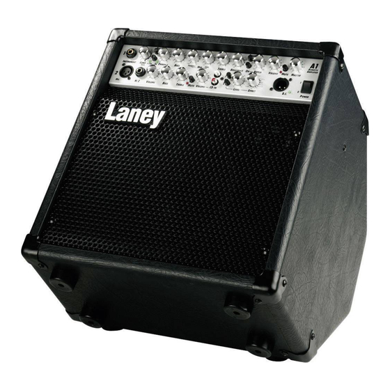
- Page 5 INTRODUCTION The A1 is a dedicated 65W acoustic amplifier loaded with a 10 inch loudspeaker and a high frequency horn in a kickback style cabinet. Its features include; three separate channels; balanced DI out; Headphone socket; FX Loop and Tuner out. Channel one has an instrument input socket;...
- Page 6 The pad switch allows you to reduce (or pad down) the input level from a guitar with an active pickup system, or a particularly loud passive pickup to prevent the guitar from overloading the preamplifier of the A1. Lights when the onboard compressor is actively compressing the signal. Compressor must be switched in with Switch in to activate the onboard compressor, this compresses the input signal giving a punchier sound.
- Page 7 Laney OPERATING INSTRUCTIONS sound. The Enhance control does this by providing a dip in the frequency-response of the amplifier at approximately 250Hz. This dip reduces some of the harmonics of the important low-frequencies around 80-120 Hz producing better definition to your sound.
- Page 8 Laney OPERATING INSTRUCTIONS 24 25 26 27 FRONT PANEL CONTROLS - continued Balanced input provided for connecting an XLR equipped input such as a low impedance microphone ( 200-600 Ohms) or a DI’d guitar etc. Input provided for connecting high impedance microphones or sources that require a high impedance connection and are fitted with a 1/4”...
- Page 9 Sets the level from the onboard digital effects section, present in the overall mix. The onboard digital effects have been custom designed by Laney to complement the A1. You have a choice of delays, flange, rotary, octave, chorus, reverb and combinations of these. Select the chosen effect here, and set the level with This XLR socket provides a low impedance output for direct injection of the amplifier signal to a mixing desk or power amplifier.
- Page 10 FX Send socket provided for connecting to external effects units input socket. You can also use the send socket as a line out if you wish. Connect the output of your external effects unit here. Any external effects device used here will affect both channels of the A1. Can be used in addition to the onboard digital effects. Page 10 /16...
- Page 11 OPERATING INSTRUCTIONS OTHER FEATURES Your A1 features a kickback style design to enable you to use it as a stage monitor, or a conventional straight combo. GENERAL NOTES Amplifier connection: In order to avoid damage, it is advisable to establish and follow a pattern for turning on and off your equipment.
- Page 12 Laney OPERATING INSTRUCTIONS SAMPLE SYSTEM - 1 Tuner Input Page12 /16...
- Page 13 Laney OPERATING INSTRUCTIONS SAMPLE SYSTEM - 2 Tuner Input Page 13 /16...
- Page 14 Laney OPERATING INSTRUCTIONS BLOCK DIAGRAM ACTIVE ACTIVE CHANNEL 1 CHANNEL 1 INPUT INPUT PROGRAM PROGRAM CHANNEL 1 CHANNEL 1 MUTE MUTE SELECT SELECT VOLUME VOLUME NOTCH NOTCH PHASE PHASE COMPRESSOR COMPRESSOR ACTIVE ACTIVE ENHANCE ENHANCE EQ SECTION EQ SECTION SECTION...
-
Page 15: Operating Instructions
Laney OPERATING INSTRUCTIONS SPECIFICATIONS Supply Voltage ~100V, ~120V, ~220V, ~230V, ~240V 50/60Hz Factory Option Mains Fuse ~220V>~240V = T1A L. ~100>~120V = T2A L (Time delay) Power Consumption 120W Output Power Rating THD%+N Typically <0.03% Loudspeaker 10” Custom Designed Driver + high frequency horn... - Page 16 Laney POWER TO THE MUSIC BLUES METAL JAZZ ROCK AMPICONS ARE HERE TO HELP! In the interest of continued product development, Laney reserves the right to amend product specification without prior notification.
Need help?
Do you have a question about the A1 and is the answer not in the manual?
Questions and answers