
Subscribe to Our Youtube Channel
Related Manuals for Intellinet 525497


Summary of Contents for Intellinet 525497
-
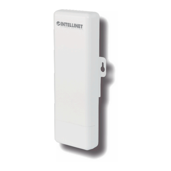
Page 1: Access Point
Wireless 150N Outdoor Range Extender / Access Point User Manual Model 525497 INT-525497-UM-1013-01... -
Page 2: Table Of Contents
Table of Contents 1. Terminology......................5 2. Introduction......................7 2.1 Package Content.....................7 2.2 Product Features....................7 2.3 Rear Panel Description..................8 2.3 Front Panel Description ................9 3. Hardware Installation ...................10 3.1 Appearance and Interface Introduction ............10 3.2 Hardware Installation Steps ...............12 4. Software Configuration ..................14 4.1 Prepare your PC to configure the Access Point ........15 4.2 Connect to the Access Point ................16 4.3 Management and configuration of the Access Point ........16... - Page 3 4.3.5.2 Port Forwarding..............65 4.3.5.3 DMZ ..................67 4.3.5.4 System Security ..............68 4.3.5.5 Content Filtering..............69 4.3.6 Administration ..................70 4.3.6.1 Management ................70 4.3.6.2 QoS ..................72 4.3.6.3 Upload Firmware ..............73 4.3.6.4 Settings Management.............73 4.3.6.5 Status..................74 4.3.6.6 System Log................75 5. FREQUENTLY ASKED QUESTIONS (FAQ) ..........76 5.1 What are and how do I find my PC’s IP and MAC addresses? ....76 5.2 What is Wireless LAN? ................76 5.3 What are ISM bands?..................76...
- Page 4 5.17 What is 802.1x Authentication?..............80 5.18 What is Temporal Key Integrity Protocol (TKIP)?........81 5.19 What is Advanced Encryption Standard (AES)? ........81 5.20 What is Inter-Access Point Protocol (IAPP)? .........81 5.21 What is Wireless Distribution System (WDS)?........81 5.22 What is Universal Plug and Play (PnP)? ..........81 5.23 What is Maximum Transmission Unit (MTU) Size? ......81 5.24 What is Clone MAC Address?..............81...
-
Page 5: Terminology
1. Terminology 3DES Triple Data Encryption Standard Advanced Encryption Standard ANSI American National Standards Institute Access Point Complementary Code Keying CSMA/CA Carrier Sense Multiple Access/Collision Avoidance CSMA/CD Carrier Sense Multiple Access/Collision Detection DDNS Dynamic Domain Name Server Diffie-Hellman Algorithm DHCP Dynamic Host Configuration Protocol DSSS Direct Sequence Spread Spectrum... - Page 6 TKIP Temporal Key Integrity Protocol UPnP Universal Plug and Play Virtual Private Network Wireless Distribution System Wired Equivalent Privacy WLAN Wireless Local Area Network Wi-Fi Protected Access...
-
Page 7: Introduction
2. Introduction This Intellinet Network Solutions Wireless 150N Outdoor Range Extender / Access Point (AP) serves multiple purposes — an access point for your wireless network supporting wireless bridge for point-to-point connections or WDS setups, an integrated antenna for long range transmissions — and brings it all together so that the devices can access a high-speed Internet connection. -
Page 8: Rear Panel Description
2.3 Rear Panel Description LED Indicator State Description The WLAN Broadband Router is powered ON. 1. PWR LED The WLAN Broadband Router is powered Off. Wireless Radio On. 2. WLAN LED Wireless Radio Off. Flashing Data is transmitting or receiving on the wireless. Port linked. -
Page 9: Front Panel Description
2.3 Front Panel Description Interfaces Description For an external antenna. You can use the SMA connector to connect with SMA connector a 5GHz external antenna. The RJ45 sockets allow LAN connection through Category 5 cables. Secondary (middle) Supports auto-sensing on 10/100M speed and half/ full duplex; complies with IEEE 802.3/ 802.3u, respectively. -
Page 10: Hardware Installation
3. Hardware Installation 3.1 Appearance and Interface Introduction Note: The product images are for reference only; refer to the actual product. 1. LED Panel 2. Waterproof sliding cover 3. Passthrough for Ethernet cable 4. Push this button to remove the upper housing... - Page 11 5. Pole Mount 6. Wall Mount 7. Secondary port with PoE 8. Main port 9. SMA connector for external antenna 10. Reset button...
-
Page 12: Hardware Installation Steps
3.2 Hardware Installation Steps Step 1: Push the button on the side to remove upper housing. Step 2: Pass Ethernet cable through the hole; insert the cable into the secondary port. Note: RJ-45 8P8C Ethernet cable is required. - Page 13 Step 3: Install the upper housing and make sure the housing is well installed. Step 4: Complete the hardware installation as shown below. Install PoE Injector DC: Insert adapter PoE: This jack is linked to the secondary port of the AP with RJ45. LAN: This jack is linked to the LAN side of a PC/hub or router/ADSL modem device with RJ45.
-
Page 14: Software Configuration
4. Software Configuration There are Web-based management and configuration functions allowing you to use this device more easily. The AP is delivered with the following factory default parameters on the Ethernet LAN interfaces. Default IP address: 192.138.2.1 Default IP subnet mask: 255.255.255.0 Web login user name: admin... -
Page 15: Prepare Your Pc To Configure The Access Point
4.1 Prepare your PC to configure the WLAN Broadband Router For Windows 2000/ XP: 1. Click the Start button and select Settings, then click Control Panel. The Control Panel window will appear. 2. Double-click the right mouse button on the Network and Dial-up Connections icon. Double-click the Local Area Connection icon. -
Page 16: Connect To The Access Point
4.2 Connect to the AP Open a Web browser — i.e., Microsoft Internet Explorer 6.1 SP1 or above — then enter 192.168.2.1 the URL field to connect the WLAN Broadband Router. 4.3 Management and configuration of the AP 4.3.1 Wizard The setup wizard will be changed when you select different operation modes. - Page 17 Step 2: Configure Wireless Settings There are four options (Disable, Open- WEP, Shared-WEP, WPA-PSK/WPA2-PSK) for the wireless security connection. Item Description Network Band Click to select a wireless band from pull-down menu. Network Mode Click to select a wireless mode from pull-down menu. Frequency (Channel) Select the wireless communication frequency/channel from pull-down menu.
- Page 18 OPEN WEP SHARED WEP...
- Page 19 WPA-PSK WPA2-PSK When you finish these settings, click Apply to save. Choose either Client or WDS, then click Next to go to Step 3.
- Page 20 Step 3: a. Configure AP Client Mode Settings b. Configure WDS Mode Settings...
-
Page 21: Gateway Mode
4.3.1.2 Gateway Mode This mode is for home networking. The Setup Wizard will guide you to configure the device to connect to your ISP (Internet Service Provider). Step 1: Configure LAN IP address settings... - Page 22 Step 2: Configure the Internet connection Click Next to go to the next step for Internet connection settings. There are five options (DHCP, Static Mode, PPPOE, L2TP, PPTP) for Internet connection on the WAN port. a. DHCP (Auto Configure) If you select the DHCP option, click Next to jump to Step 3.
- Page 23 b. Static Mode (fixed IP) If you select Static Mode (fixed IP), fill in these fields. Item Description IP Address Fill in the IP address for the WAN interface. Subnet Mask Fill in the subnet mask for the WAN interface. Default Gateway Fill in the default gateway for WAN interface outgoing data packets.
- Page 24 c. PPPOE (ADSL) If you select PPPOE, fill in these fields. Item Description User Name If you select the PPPoE support on the WAN interface, fill in the user name to log in to the PPPoE server. Password If you select the PPPoE support on the WAN interface, fill in the password to log in to the PPPoE server.
- Page 25 d. L2TP If you select L2TP, fill in these fields. Item Description L2TP Server IP Allows you to make a tunnel with a remote site directly to secure the data transmission Address among the connection. You can use embedded L2TP client supported by this device to make a VPN connection.
- Page 26 e. PPTP If you select PPTP, fill in these fields. Item Description PPTP Server IP Allows you to make a tunnel with a remote site directly to secure the data Address transmission among the connection. You can use embedded PPTP client supported by this device to make a VPN connection.
- Page 27 Step 3: Configure Wireless Settings There are three options (Disable, WEP, WPA-PSK/WPA2-PSK) for the Wireless security connection. Item Description Network Band Click to select wireless band from pull-down menu. Network Mode Click to select wireless mode from pull-down menu. Frequency (Channel) Select the wireless communication frequency/channel from pull-down menu.
- Page 28 OPEN WEP SHARED WEP...
- Page 29 WPA-PSK WPA2-PSK When you finish these settings, click Apply to save. Choose either Client or WDS, then click Next to go to Step 3.
-
Page 30: Wisp Mode
4.3.1.3 WISP Mode This mode is for home networking. The Setup Wizard will guide you to configure the device to connect to your ISP (Internet Service Provider). Step 1: Configure LAN IP address settings... - Page 31 Step2: Configure Internet connection Click Next to go to the Internet connection settings. There are five options (DHCP, Static Mode, PPPOE, L2TP, PPTP) for Internet connection on the WAN port. a. DHCP (Auto Configure) If you select DHCP option, click Next to jump to Step 3.
- Page 32 b. Static Mode (fixed IP) If you select Static Mode (fixed IP), fill in these fields. Item Description IP Address Fill in the IP address for the WAN interface. Subnet Mask Fill in the subnet mask for the WAN interface. Default Gateway Fill in the default gateway for WAN interface outgoing data packets.
- Page 33 c. PPPOE (ADSL) If you select PPPOE, fill in these fields. Item Description User Name If you select the PPPoE support on WAN interface, fill in the user name to log in to the PPPoE server. Password If you select the PPPoE support on WAN interface, fill in the password to log in to the PPPoE server.
- Page 34 d. L2TP If you select L2TP, fill in these fields. Item Description L2TP Server IP Allows you to make a tunnel with remote site directly to secure the data transmission Address among the connection. You can use embedded L2TP client supported by this device to make a VPN connection.
- Page 35 e. PPTP If you select PPTP, fill in these fields. Item Description PPTP Server IP Allows you to make a tunnel with remote site directly to secure the data Address transmission among the connection. You can use embedded PPTP client supported by this device to make a VPN connection.
- Page 36 Step 3: Configure Wireless Settings There are five options (Disable, OPENWEP,WPA-PSK WPA2-PSK) for the Wireless security connection. Item Description Network Band Click to select wireless band from pull-down menu. Network Mode Click to select wireless mode from pull-down menu. Frequency (Channel) Select the wireless communication frequency/channel from pull-down menu.
- Page 37 OPEN WEP When you finish these settings, click Next to jump to Step 4. SHARED WEP When you finish these settings, click Next to jump to Step 4.
- Page 38 WPA-PSK When you finish these settings, click Next to jump to Step 4.
- Page 39 WPA2-PSK Item Description Network Band Click to select wireless band from pull-down menu. Network Mode Click to select wireless mode from pull-down menu. Frequency (Channel) Select the wireless communication frequency/channel from pull-down menu. Network Name (SSID) It is the wireless network name. The SSID can be 32 bytes long. Channel Bandwidth Select the operating channel width 20 MHz or 20/40 MHz.
- Page 40 Step 4. Configure AP Client setting SCAN APs...
-
Page 41: Operation Mode
4.3.2 Operation Mode a. Bridge: Bridge mode allows all Ethernet and wireless interfaces to be bridged into a single bridge interface. b. Gateway: Gateway mode allows the first Ethernet port to be treated as a WAN port. The Ethernet port and the wireless interface are bridged together and are treated as LAN ports. - Page 42 c. Wireless ISP The Wireless ISP mode allows that the wireless interface is treated as a WAN port, and the Ethernet ports are LAN ports.
-
Page 43: Internet Settings
4.3.3 Internet Settings 4.3.3.1 WAN a. STATIC Item Description IP Address Fill in the IP address for the WAN interface. Subnet Mask Fill in the subnet mask for the WAN interface. Default Gateway Fill in the default gateway for WAN interface outgoing data packets. Primary DNS Fill in the IP address of Domain Name Server 1. - Page 44 b. DHCP Item Description Hostname Fill in the host name for the DHCP server. The default value is empty. MAC Clone Use the NIC MAC address of the PC on the LAN side as the MAC address of the WAN interface.
- Page 45 . PPPoE Item Description User Name If you select the PPPoE support on the WAN interface, fill in the user name to log in to the PPPoE server. Password If you select the PPPoE support on the WAN interface, fill in the password to log in to the PPPoE server.
- Page 46 d. L2TP Item Description Server IP Allows you to make a tunnel with a remote site directly to secure the data transmission among the connections. You can use embedded L2TP client supported by this device to make a VPN connection. If you select the L2TP support on the WAN interface, fill in the IP address for it.
- Page 47 e. PPTP Item Description Server IP Allows you to make a tunnel with a remote site directly to secure the data transmission among the connection. You can use embedded PPTP client supported by this device to make a VPN connection. If you select the PPTP support on the WAN interface, fill in the IP address for it.
-
Page 48: Lan
4.3.3.2 LAN Item Description Use the NIC MAC address of a PC on the LAN side as the MAC address of the MAC Address WAN interface. IP Address Fill in the IP address for the WAN interface. Subnet Mask Fill in the subnet mask for the WAN interface. DHCP Type Disable: Disable the DHCP server on LAN side. -
Page 49: Vpn Passthrough
4.3.3.3 VPN Passthrough Item Description L2TP Passthrough Select enable or disable the L2TP passthrough function from pull-down menu. IPSec Passthrough Select enable or disable the IPSec passthrough function from pull-down menu. PPTP Passthrough Select enable or disable the PPTP passthrough function from pull-down menu. -
Page 50: Wireless Settings
4.3.4 Wireless Settings 4.3.4.1 Basic Item Description Click Wireless OFF to turn off the wireless RF radio. Click Wireless ON to Wireless On/Off turn on the wireless RF radio. Antenna Switch Select Internal antenna or External antenna. The default is Internal antenna. Wireless Mode Click to select a wireless mode from pull-down menu. - Page 51 connection between a wireless client and this device. BSSID Show the MAC address of the wireless interface. Frequency Select the wireless communication frequency/channel from the pull-down (Channel) menu. Operating Mode Select “Mixed Mode” for 11b/g/n mode or “Green Field” for 11n mode. Channel Select the operating channel width 20 MHz or 20/40 MHz.
-
Page 52: Advanced
4.3.4.2 Advanced Item Description Beacon Interval Beacons are the packets sent by the access point to synchronize the wireless network. The beacon interval is the time interval between beacons sent by this unit in AP or AP+WDS operation. The default and recommended beacon interval is 100 milliseconds. - Page 53 can be useful in areas where many client devices are associating with the device, or in areas where the clients are far apart and can detect only the device and not each other. You can enter a setting ranging from 0 to 2347 bytes. TX Power The default TX power is 100%.
-
Page 54: Security
4.3.4.3 Security a. Disable If you set Security Mode to Disable, the wireless data transmission will not include encryption to prevent from unauthorized access and monitoring. - Page 55 b. OPEN-WEP // SHARED-WEP If you set Security Mode to OPEN-WEP or SHARED-WEP, fill in the related configurations as below. Item Description Default Key Specify a Key number. WEP Keys (1-4) When you select WEPAUTO, input 5, 13 (ASCII), 10 or 26 (hexadecimal) characters for WEP Key.
- Page 56 c. WPA-PSK/WPA2PSK If you set Security Mode to “WPAPSK or WPA2-PSK,” fill in the related configurations as below. Item Description WPA Cipher Suite Select TKIP, AES or TKIPAES for WPA algorithms.
- Page 57 Pre-Shared Key Fill in a passphrase like “test wpa 123” or a hexadecimal string like “65E4 E123 456 E1.” Key Renewal Fill in a number for Group Key Renewal interval time. Interval d. WPA-RADIUS/WPA2-RADIUS...
- Page 58 Item Description WPA Cipher Suite Select TKIP or AES for WPA algorithms. Key Renewal Fill in a number for Group Key Renewal interval time. Interval IP Address Enter the RADIUS Server’s IP Address provided by your ISP. Port Enter the RADIUS Server’s port number provided by your ISP. (The Default is 1812.) Shared Secret Enter the password shared with the RADIUS Server.
- Page 59 e. 802.1X Item Description Select Disabled or Enabled for WEP. IP Address Enter the RADIUS Server’s IP Address provided by your ISP. Port Enter the RADIUS Server’s port number provided by your ISP. (The Default is 1812.) Shared Secret Enter the password shared with the RADIUS Server. Session Timeout Session timeout interval is for 802.1x re-authentication setting.
- Page 60 f. Access Policy Item Description Policy Select Disabled, Allow or Reject from the drop-down menu to choose a wireless access control mode. This is a security control function; only those clients registered in the access control list can link to this WLAN device. Add a station Fill in the MAC address of a client to register this device’s access capability.
-
Page 61: Site Survey
4.3.4.4 Site Survey You can configure AP Client parameters here. -
Page 62: Wps
4.3.4.5 WPS Item Description Select to Enable or Disable the Wi-Fi Protected Setup function. Then click Apply for it to take effect. WPS Summary After enabling the WPS function, if there is connection the WPS Summary will show related information and status. AP PIN This shows the AP’s PIN (Personal Identification Number) code that the enrollee should enter to make a connection. -
Page 63: Firewall
4.3.5 Firewall 4.3.5.1 MAC/IP/Port Filtering Item Description MAC/IP/Port Select to Enable or Disable the MAC/IP/Port Filtering function. Filtering Item Description Source MAC Fill in the MAC address of the source NIC to restrict data transmission. address Dest IP Address Fill in the IP address of the destination to restrict data transmission. Source IP Address Fill in the IP address of the source to restrict data transmission. - Page 64 Comment Make a comment for the filtering policy. Item Description □ Make a mark for the next action. Delete Selected Click Delete Selected to delete all that you selected. Reset Click Reset to clear selected items.
-
Page 65: Port Forwarding
4.3.5.2 Port Forwarding Item Description Port Forwarding Select to Enable or Disable the Port Forwarding function. IP Address To forward data packets coming from the WAN to a specific IP address hosted in the local network behind the NAT firewall, fill in the IP address. Port Range To forward data packets coming from the WAN to a specific IP address hosted in the local network behind the NAT firewall, fill in the port range. - Page 66 Item Description Virtual Server Select to Enable or Disable the Virtual Server function. IP Address To forward data packets coming from the WAN to a specific IP address hosted in the local network behind the NAT firewall, fill in the IP address. Public Port To forward data packets coming from the WAN to a specific IP address hosted in the local network behind the NAT firewall, fill in the public port.
-
Page 67: Dmz
4.3.5.3 DMZ Item Description DMZ Settings Enable or Disable the DMZ function. DMZ IP Address To support DMZ in your firewall design, fill in the IP address of the DMZ host that can be accessed from the WAN interface. -
Page 68: System Security
4.3.5.4 System Security Item Description Remote Select to Deny or Allow the remote management function. management Ping from WAN Select Disable or Enable to allow pinging from the WAN. Filter SPI Firewall Select to Disable or Enable the SPI firewall function. -
Page 69: Content Filtering
4.3.5.5 Content Filtering Item Description Keyword Enter the name of the website you wish to filter. Click to save the keyword(s). Delete Click Delete to delete all that you selected. Reset Click Reset to clear selected items. -
Page 70: Administration
4.3.6 Administration 4.3.6.1 Management Item Description Username Fill in the user name for web management login control. Password Fill in the password for web management login control. Current Time It shows the current time. Time Zone Select the time zone in your country from the pull-down menu. NTP Server Fill in the NTP server IP address. - Page 71 Item Description Dynamic DNS Select the DDNS provider you registered with from the drop-down menu. Provider Account Fill in the account of the DDNS you registered with. Password Fill in the password of the DDNS you registered. DDNS Fill in the domain name that you registered.
-
Page 72: Qos
4.3.6.2 QoS Item Description Uplink Speed Input the uplink maximum upload speed. Downlink Speed Input the downlink maximum upload speed. Local IP Address Enter the local IP address. Uplink Bandwidth Enter the limit upload bandwidth. Downlink Enter the limit downlink bandwidth. Bandwidth... -
Page 73: Upload Firmware
4.3.6.3 Upload Firmware Item Description Location Click the Browse button to select the new firmware image file on the PC. Then click the Apply button to upgrade the firmware. 4.3.6.4 Settings Management Item Description Export Button Click Export to export the current configuration to your PC. Settings file Click Browse to select the configuration file from your PC, then click Import to location... -
Page 74: Status
4.3.6.5 Status This page shows the current status and some basic settings of the device, including system info, Internet configurations and local network info. -
Page 75: System Log
4.3.6.6 System Log This page is used to view system logs. Item Description Refresh Click the Refresh button to refresh the log shown on the screen. Clear Click the Clear button to clear the log displayed on the screen. -
Page 76: Frequently Asked Questions (Faq)
5. FREQUENTLY ASKED QUESTIONS (FAQ) 5.1 What are (and how do I find) my PC’s IP and MAC addresses? IP address is the identifier for a computer or device on a TCP/IP network. Networks using the TCP/IP protocol route messages based on the IP address of the destination. The format of an IP address is a 32-bit numeric address written as four numbers separated by periods. -
Page 77: How Does Wireless Networking Work
5.4 How does wireless networking work? The 802.11 standard defines two modes: infrastructure mode and ad hoc mode. In infrastructure mode, the wireless network consists of at least one access point connected to the wired network infrastructure and a set of wireless end stations. This configuration is called a Basic Service Set (BSS). An Extended Service Set (ESS) is a set of two or more BSSs forming a single sub-network. -
Page 78: What Is Bssid
5.5 What is BSSID? A six-byte address is that distinguishes a particular access point from others. Also known simply as SSID. Serves as a network ID or name. 5.6 What is ESSID? The Extended Service Set ID (ESSID) is the name of the network you want to access. It is used to identify different wireless networks. -
Page 79: What Is Fragment Threshold
5.10 What is Fragment Threshold? This protocol uses the frame fragmentation mechanism defined in IEEE 802.11 to achieve parallel transmissions. A large data frame is fragmented into several fragments, each of a size equal to the fragment threshold. By tuning the fragment threshold value, we can get varying fragment sizes. The determination of an efficient fragment threshold is an important issue in this scheme. -
Page 80: What Is Preamble Type
5.13 What is Preamble Type? There are two preamble types defined in IEEE 802.11 specifications. A long preamble basically gives the decoder more time to process the preamble. All 802.11 devices support a long preamble. The short preamble is designed to improve efficiency (for example, for VoIP systems). The difference between the two is in the synchronization field. -
Page 81: What Is Temporal Key Integrity Protocol (Tkip)
5.18 What is Temporal Key Integrity Protocol (TKIP)? The Temporal Key Integrity Protocol, pronounced tee-kip, is part of the IEEE 802.11i encryption standard for wireless LANs. TKIP is the next generation of WEP, the Wired Equivalency Protocol, which is used to secure 802.11 wireless LANs. TKIP provides per-packet key mixing, a message integrity check and a re-keying mechanism, thus fixing the flaws of WEP.
Need help?
Do you have a question about the 525497 and is the answer not in the manual?
Questions and answers