Table of Contents
Advertisement
Quick Links
Advertisement
Table of Contents

Related Manuals for Supero B1SA4-2750F


Summary of Contents for Supero B1SA4-2750F
- Page 1 B1SA4-2750F B1SA4-2550F USER’S MANUAL Revision 1.0...
- Page 2 This product, including software and docu- mentation, is the property of Supermicro and/or its licensors, and is supplied only under a license. Any use or reproduction of this product is not allowed, except as expressly permitted by the terms of said license.
-
Page 3: About This Motherboard
Intel® ATOM C2750 (8 Cores) or four Intel ATOM C2550 (4 Cores) CPUs. Each of the four nodes of the B1SA4-2750F/B1SA4-2550F supports up to 32GB of memory, and features two SATA 3.0 ports on the backplane, two Serdes 2.5Gb/s, and an ASPEED BMC on board. -
Page 4: Conventions Used In The Manual
B1SA4-2750F/B1SA4-2550F Motherboard User’s Manual Conventions Used in the Manual: Special attention should be given to the following symbols for proper installation and to prevent damage done to the components or injury to yourself: Danger/Caution: Instructions to be strictly followed to prevent catastrophic... -
Page 5: Contacting Supermicro
Super Micro Computer, Inc. 980 Rock Ave. San Jose, CA 95131 U.S.A. Tel: +1 (408) 503-8000 Fax: +1 (408) 503-8008 Email: marketing@supermicro.com (General Information) support@supermicro.com (Technical Support) Web Site: www.supermicro.com Europe Address: Super Micro Computer B.V. Het Sterrenbeeld 28, 5215 ML... -
Page 6: Table Of Contents
B1SA4-2750F/B1SA4-2550F Motherboard User’s Manual Table of Contents Preface About This Motherboard ....................iii Manual Organization ..................... iii Conventions Used in the Manual: .................iv Contacting Supermicro ....................v Chapter 1 Introduction Overview ......................1-1 Checklist ......................1-1 Motherboard Features ..................1-6 Special Features ..................... 1-9 Recovery from AC Power Loss ............... - Page 7 How to Start the Setup Utility ................. 4-2 Main Setup ...................... 4-2 The following Main menu items will display: ..........4-3 System Date/System Time ................ 4-3 Supermicro A1SAi & A1SRi Series ............4-3 Version ......................4-3 Build Date ....................4-3 Memory Information ................... 4-3...
- Page 8 B1SA4-2750F/B1SA4-2550F Motherboard User’s Manual Total Memory ....................4-3 4-3 Advanced Setup Configurations..............4-4 Boot Feature ....................4-4 Quiet Boot ....................4-4 AddOn ROM Display Mode ................ 4-4 Bootup Num-Lock ..................4-4 Wait For 'F1' If Error ................... 4-5 Interrupt 19 Capture ................... 4-5 Power Configuration ..................
- Page 9 Table of Contents PECI Trusted ....................4-9 PECI SMBus Speed ................... 4-9 Turbo (Available if Intel® EIST technology is Enabled) ......4-9 RAPL ......................4-9 MSR 606 PKG_POWER_SKU_UNIT ............4-9 MSR 610 PKG_TURBO_PWR_LIM ............4-9 MSR 670 PKG_TURBO_CFG1 ..............4-9 MSR 672_TURBO_WKLD_CFG2 ..............
- Page 10 B1SA4-2750F/B1SA4-2550F Motherboard User’s Manual Scrambler ....................4-15 Slow Power Down Exit ................4-15 Verf Override Enable ................4-15 South Bridge ..................... 4-16 Legacy USB Support ................4-16 XHCI Hand-Off ..................4-16 EHCI Hand-Off ..................4-16 USB Mass Storage Driver Support ............4-17 USB Hardware Delays and Time-Outs ............
- Page 11 Table of Contents Onboard LAN Option ROM Select ............4-20 Load Onboard LAN1 OPROM / Load Onboard LAN2 OPROM ....4-20 ACPI Settings .................... 4-20 High Precision Event Timer ..............4-20 WHEA Support ..................4-21 AST2400 Super IO Chip ............... 4-21 ...
- Page 12 B1SA4-2750F/B1SA4-2550F Motherboard User’s Manual LAN Channel 1: This feature allows the user to configure the setting for LAN Port 1....................4-27 Configuration Address Source ..............4-27 Security Settings ................... 4-29 Administrator Password ................4-29 User Password ..................4-29 Secure Boot Menu ..................4-29 Secure Boot Mode ................... 4-29 Key Management .................. 4-30 Factory Default Key Provision ..............
- Page 13 Table of Contents Restore Defaults ..................4-34 Save As User Defaults ................4-34 Restore User Defaults ................4-34 Boot Override ................... 4-34 Appendix A BIOS Error Beep Codes BIOS Error Beep Codes .................A-1 Appendix B Software Installation Instructions Installing Drivers ....................B-1 B-2 Configuring SuperDoctor ®...
- Page 14 B1SA4-2750F/B1SA4-2550F Motherboard User’s Manual Notes...
-
Page 15: Introduction
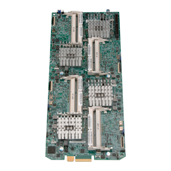
Checklist Congratulations on purchasing your computer motherboard from an acknowledged leader in the industry. Supermicro boards are designed with the utmost attention to detail to provide you with the highest standards in quality and performance. Please check that the following items have all been included with your motherboard. - Page 16 B1SA4-2750F/B1SA4-2550F Motherboard User’s Manual Motherboard Image Note: All graphics shown in this manual were based upon the latest PCB Revision available at the time of publishing of the manual. The motherboard you've received may or may not look exactly the same as the graphics...
- Page 17 Chapter 1: Introduction Motherboard Layout Important Notes to the User • See Chapter 2 for detailed information on jumpers, I/O ports and JF1 front panel connections. ▪ • " " indicates the location of "Pin 1". • Jumpers not indicated are for testing only.
- Page 18 B1SA4-2750F/B1SA4-2550F Motherboard User’s Manual Motherboard Quick Reference JBT1 P1-DIMMA1 JWD1 CPU1 P1-DIMMB1 LED1 JKVM1 LED2 P2-DIMMA1 P2-DIMMB1 CPU2 JWD2 JBT2 JKVM2 JKVM3 JBT3 P3-DIMMA1 CPU3 P3-DIMMB1 JWD3 LED4 LED3 P4-DIMMA1 P4-DIMMB1 JBT4 JWD4 JKVM4 POWER CPU4...
- Page 19 Chapter 1: Introduction Motherboard Jumpers and Connectors Jumper Name Description Default (See Chapter 2 in User JBT1~JBT4 CMOS Clear Manual) JWD1~JWD4 Watch Dog Timer RST/NMI Selection Pins 1-2 (Reset) Connector Name Description LED1~LED4 BMC Heartbeat LED JKVM1~JKVM4 USB / VGA / UART Interface CPU1~CPU4 Onboard CPU P1~P4 DIMMA1~DIMMB1...
-
Page 20: Motherboard Features
B1SA4-2750F/B1SA4-2550F Motherboard User’s Manual Motherboard Features One Intel® ATOM C2750 (8 cores) or ATOM C2550 (4 cores) per node, total of four (4) CPUs on board. Memory Two (2) SODIMM slots per node supports up to 32GB of DDR3 Unbuffered, ECC SODIMM memory, up to 1600MHz. - Page 21 Chapter 1: Introduction CD Utilities BIOS flash upgrade utility Drivers and software for Intel® C602 chipset utilities Other ROHS 6/6 (Full Compliance, Lead Free) FCC A, EuP Lot 6, WHQL Dimensions ATX form factor (11.50" x 4.7")
-
Page 22: Motherboard Block Diagram
B1SA4-2750F/B1SA4-2550F Motherboard User’s Manual Motherboard Block Diagram DDR3 (CHA) DDR3 (CHA) DIMMA1 DIMMA1 1600/1333 MHz 1600/1333 MHz DDR3 (CHB) DDR3 (CHB) DIMMB1 DIMMB1 1600/1333 MHz 1600/1333 MHz 2 x USB 2.0 2 x USB 2.0 480 Mbit/s 480 Mbit/s Connector Connector PCIE 2.0 x1... -
Page 23: Special Features
Chapter 1: Introduction Special Features Recovery from AC Power Loss Basic I/O System (BIOS) provides a setting for you to determine how the system will respond when AC power is lost and then restored to the system. You can choose for the system to remain powered off (in which case you must press the power switch to turn it back on), or for it to automatically return to a power-on state. -
Page 24: Acpi Features
B1SA4-2750F/B1SA4-2550F Motherboard User’s Manual This feature is available when the system is used with Supero Doctor III in the Windows OS environment or used with Supero Doctor II in Linux. Supero Doctor is used to notify the user of certain system events. For example, you can also configure Supero Doctor to provide you with warnings when the system temperature, CPU temperatures, voltages and fan speeds go beyond predefined thresholds. -
Page 25: Advanced Power Management
Chapter 1: Introduction Advanced Power Management Intel Intelligent Power Node Manager (NM) ® The Intel Intelligent Power Node Manager (IPNM) provides your system with ® real-time thermal control and power management for maximum energy efficiency. Although IPNM Specification Version 1.5 is supported by the BMC (Baseboard Management Controller), your system must also have IPNM-compatible Manage- ability Engine (ME) firmware installed to use this feature. Manageability Engine (ME) The Manageability Engine, which is an ARC controller embedded in the IOH (I/O Hub), provides Server Platform Services (SPS) to your system. - Page 26 B1SA4-2750F/B1SA4-2550F Motherboard User’s Manual Notes 1-12...
-
Page 27: Installation
Chapter 2: Installation Chapter 2 Installation Static-Sensitive Devices Electrostatic-Discharge (ESD) can damage electronic com ponents. To avoid damaging your system board, it is important to handle it very carefully. The following measures are generally sufficient to protect your equipment from ESD. Precautions •... -
Page 28: System Memory
CAUTION Exercise extreme care when installing or removing DIMM modules to prevent any possible damage. Note: Check the Supermicro website for a list of memory modules that have been validated with the B1SA4-2750F/B1SA4-2550F motherboard. How to Install SODIMMs Each of the four nodes has its own memory bank. Populate Channel A first, the Channel B. -
Page 29: Memory Population Guidelines
Chapter 2: Installation Memory Population Guidelines When installing memory modules, the SODIMM slots should be populated in the fol- lowing order: DIMMA1, DIMMB1. • Always use DDR3 SODIMM modules of the same size, type and speed. • Mixed DIMM speeds can be installed. However, all DIMMs will run at the speed of the slowest DIMM. -
Page 30: The So Dimm Socket
B1SA4-2750F/B1SA4-2550F Motherboard User’s Manual The SO DIMM Socket Align Position the SO DIMM module's bottom key so it aligns with the receptive point on the slot. Insert the SO DIMM module vertically at about a 45 degree Press down until the module angle. -
Page 31: Motherboard Installation
Chapter 2: Installation Motherboard Installation All motherboards have standard mounting holes to fit different types of chassis. Make sure that the locations of all the mounting holes for both motherboard and chassis match. Although a chassis may have both plastic and metal mounting fas- teners, metal ones are highly recommended because they ground the motherboard to the chassis. - Page 32 B1SA4-2750F/B1SA4-2550F Motherboard User’s Manual The B1SA4-2750F/B1SA4-2550F motherboard fits into a mounting tray, that also holds the hard drives. See the image below: Mounting Tray B1SA4-2750F/B1SA4-2550F Motherboard Hard Disk Drives Microblade Chassis Mounting tray with B 1 S A 4 - 2 7 5 0 F /...
-
Page 33: Installing The Motherboard
Chapter 2: Installation Installing the Motherboard 1. Locate the mounting holes on the motherboard. 2. Locate the matching mounting holes on the mounting tray. Align the mounting holes on the motherboard against the mounting holes on the mounting tray 3. Install standoffs in the mounting tray as needed. 4. -
Page 34: Connecting Cables & Optional Devices
B1SA4-2750F/B1SA4-2550F Motherboard User’s Manual Connecting Cables & Optional Devices This section provides brief descriptions and pin-out definitions for onboard headers and connectors. Be sure to use the correct cable for each header or connector. I/O Edge Connector When the motherboard is installed inside the A. -
Page 35: Kvm Connector (Jkvm1~4)
Chapter 2: Installation KVM Connector (JKVM1~4) A. JKVM1 Each of the four nodes in the motherboard B. JKVM2 has its own KVM (Keyboard, Video, Mouse) C. JKVM3 connector. Each of these serves as a USB / D. JKVM4 VGA / UART Interface for each of the nodes to control them independently. -
Page 36: Jumper Settings
B1SA4-2750F/B1SA4-2550F Motherboard User’s Manual Jumper Settings Explanation of Jumpers To modify the operation of the motherboard, jumpers can be used to choose between op- tional settings. Jumpers create shorts between two pins to change the function of the connec- tor. Pin 1 is identified with a square solder pad on the printed circuit board. -
Page 37: Clear Cmos (Jbt1~4)
Chapter 2: Installation Clear CMOS (JBT1~4) JBT is used to clear CMOS. Instead of pins, A. JBT1 this "jumper" consists of contact pads to pre- B. JBT2 vent accidental clearing of CMOS. To clear C. JBT3 CMOS, use a metal object such as a small D. - Page 38 B1SA4-2750F/B1SA4-2550F Motherboard User’s Manual Notes 2-12...
-
Page 39: Troubleshooting
Chapter 3: Troubleshooting Chapter 3 Troubleshooting Troubleshooting Procedures Use the following procedures to troubleshoot your system. If you have followed all of the procedures below and still need assistance, refer to the ‘Technical Support Procedures’ and/or ‘Returning Merchandise for Service’ section(s) in this chapter. Always disconnect the AC power cord before adding, changing or installing any hardware components. -
Page 40: No Video
1. Make sure that the SODIMM modules are properly installed and fully seated in the slots. 2. You should be using memory recommended by Supermicro. Also, it is recom- mended that you use the memory modules of the same type and speed for all DIMMs in the system. -
Page 41: Technical Support Procedures
Before contacting Technical Support, please make sure that you have followed all the steps listed below. Also, Note that as a motherboard manufacturer, Supermicro does not sell directly to end users, so it is best to first check with your distributor or reseller for troubleshooting services. -
Page 42: Frequently Asked Questions
Answer: It is recommended that you do not upgrade your BIOS if you are not experiencing any problems with your system. Updated BIOS files are located on our website at http://www.supermicro.com/support/bios/. Please check our BIOS warning message and the information on how to update your BIOS on our web site. -
Page 43: Returning Merchandise For Service
You can obtain service by calling your vendor for a Returned Merchandise Authorization (RMA) number. For faster service, you may also obtain RMA authorizations online (http://www.supermicro. com/support/rma/). When you return the motherboard to the manufacturer, the RMA number should be prominently displayed on the outside of the shipping carton, and mailed prepaid or hand-carried. - Page 44 B1SA4-2750F/B1SA4-2550F Motherboard User's Manual Notes...
-
Page 45: Introduction
When an option is selected in the left frame, it is highlighted in white. Often a text message will accompany it. (Note: the AMI BIOS has default text messages built in. Supermicro retains the option to include, omit, or change any of these text messages.) The AMI BIOS setup utility uses a key-based navigation system called "hot keys". -
Page 46: How To Start The Setup Utility
Flashing the wrong BIOS can cause irreparable damage to the system. In no event shall Supermicro be liable for direct, indirect, special, incidental, or consequential dam- ages arising from a BIOS update. If you have to update the BIOS, do not shut down or reset the system while the BIOS is updating. -
Page 47: The Following Main Menu Items Will Display
Day MM/DD/YY format. The time is entered in HH:MM:SS format. Note: The time is in the 24-hour format. For example, 5:30 P.M. appears as 17:30:00. The following BIOS items will also be displayed: Supermicro B1SA4-F Version Build Date Memory Information Total Memory This displays the total size of memory available in the system. -
Page 48: Advanced Setup Configurations
B1SA4-2750F/B1SA4-2550F Motherboard User’s Manual Advanced Setup Configurations Use the arrow keys to select Boot Setup and press <Enter> to access the submenu items. Warning: Take Caution when changing the Advanced settings. An incorrect value, a very high DRAM frequency, or an incorrect DRAM timing setting may make the system unstable. -
Page 49: Wait For 'F1' If Error
Chapter 4: AMI BIOS Wait For 'F1' If Error Use this feature to force the system to wait until the 'F1' key is pressed if an error occurs. The options are Disabled and Enabled. Interrupt 19 Capture Interrupt 19 is the software interrupt that handles the boot disk function. When this item is set to Enabled, the ROM BIOS of the host adaptors will "capture"... -
Page 50: Cpu Configuration
B1SA4-2750F/B1SA4-2550F Motherboard User’s Manual CPU Configuration The following CPU information will be displayed: • Processor ID • Processor Frequency • Microcode Revision • L1 Cache RAM • L2 Cache RAM • Processor Version Clock Spread Spectrum If this feature is set to Enabled, the BIOS utility will monitor the level of Electro- magnetic Interference caused by the components and will attempt to reduce the interference whenever needed. -
Page 51: Cpu C-States
Chapter 4: AMI BIOS CPU C-States C-States architecture, a processor power management platform developed by Intel, can further reduce power consumption from the basic C1 (Halt State) state that blocks clock cycles to the CPU. Select Enabled for CPU C-Sates support. The options are Enabled and Disabled. -
Page 52: Fast String
B1SA4-2750F/B1SA4-2550F Motherboard User’s Manual Fast String Select Enabled to enable Fast String support for REP MOVS/STOS, which will carry out Repeat-String Operation instructions to move a string of commands to another location (MOVS) or to add a string of commands to an existing instruction code (STOS). -
Page 53: Aes-Ni
Chapter 4: AMI BIOS AES-NI Select Enabled to use the Advanced Encryption Standard in the processor. The options are Enabled and Disabled. PECI Enable Select Enabled to enable PECI (Platform Environment Control Interface) support, which will enhance CPU thermal management to achieve power efficiency. The options are Disabled and Enabled. -
Page 54: Cpu Core Ratio
B1SA4-2750F/B1SA4-2550F Motherboard User’s Manual Active Processor Cores This feature determines how many CPU cores will be activated for each CPU. When all is selected, all cores in the CPU will be activated. (Please refer to Intel's web site for more information.) The options are All, 1, 2, and 3. - Page 55 Chapter 4: AMI BIOS Pass Gate Stress Test Configuration Pass Gate Test Select Enabled to use the Pass Gate test. The options are Disabled and En- abled. Pass Gate Test Direction This feature specifies how the BIOS setup utility should perform the Pass Gate test (from the lowest memory to the highest or from the highest memory to the lowest.) The options are Lowest to Highest and Highest to Lowest.
-
Page 56: Fast Boot
B1SA4-2750F/B1SA4-2550F Motherboard User’s Manual Pass Gate MonteCarlo Select Enabled to enable a algorithm search to find the maximum value of the Pass Gate test. The options are Disabled and Enabled. Pass Gate Maximum Failures Use this feature to specify the maximum number that Pass Gate failures will be counted for. -
Page 57: Cke Power Down
Chapter 4: AMI BIOS CKE Power Down Select Enabled to enable CKE Power Down support which controls the low power mode for RAM in the active power standby mode. The options are Enabled, and Disabled. ECC (Error Correctable Correction) Select Enabled to enable ECC support. The options are Enabled and Disabled. Faulty Part Tracking Select Enabled to support faulty part tracking for the system to keep track of faulty memory parts. -
Page 58: E Segment In Dram
B1SA4-2750F/B1SA4-2550F Motherboard User’s Manual E Segment In DRAM When this feature is set to Enabled, Target E segment will be routed to DRAM during memory read and write cycles. The options are Enabled and Disabled. F Segment In DRAM When this feature is set to Enabled, Target F segment will be routed to DRAM during memory read and write cycles. -
Page 59: Pmop Value For Pco
Chapter 4: AMI BIOS PMOP Value for PCO Use the keyboard to enter the Opcode value for the SPID Power Mode. The default setting is 4. PMOP Value for PCX Use the keyboard to enter the PCX value for the SPID Power Mode. The default setting is 7. -
Page 60: South Bridge
B1SA4-2750F/B1SA4-2550F Motherboard User’s Manual tRTP - the options are Auto, 4 through 7. tRRD - the options are Auto, 4 through 7. tFAW - the options are Auto, 16 through 33. tCCD - the options are Auto, 4, 12 and 18. -
Page 61: Usb Mass Storage Driver Support
Chapter 4: AMI BIOS USB Mass Storage Driver Support Select Enabled for USB Mass Storage Driver support. The options are Enabled and Disabled. Port 60/64 Emulation This feature enables or disables I/O port 60h/64h emulation support. This fea- ture should be enabled for complete USB keyboard legacy support for operat- ing systems that cannot detect the presence of USB devices. -
Page 62: Sata Mode
B1SA4-2750F/B1SA4-2550F Motherboard User’s Manual SATA Mode This item sets SATA device mode. The options are IDE and AHCI. LPM (Link Power Management) Select Enabled to support Link Power Management to improve system power management. The options are Disabled, and Enabled. -
Page 63: Vga Palette Snoop
Chapter 4: AMI BIOS VGA Palette Snoop Select Enabled to support VGA palette register snooping which will allow the PCI cards that do not contain their own VGA color palettes to examine the video cards palette to mimic it for proper color display. The options are Disabled and Enabled. PERR# Generation Select Enabled to allow a PCI device to generate a PERR number for a PCI Bus Signal Error Event. -
Page 64: Pcie Slot 1 Oprom
B1SA4-2750F/B1SA4-2550F Motherboard User’s Manual using a legacy storage device. The options are Do Not Use, UEFI Only Legacy Only, Legacy First, UEFI First. PCIe Slot 1 OPROM Select Enabled to enable Option ROM support to boot the computer using a net- work interface device install in the slot specified above. -
Page 65: Whea Support
Chapter 4: AMI BIOS tion embedded in the CPU. The High Performance Event Timer is used to replace the 8254 Programmable Interval Timer. The options are Enabled and Disabled. WHEA Support This feature Enables the Windows Hardware Error Architecture (WHEA) support for the Windows 2008 (or a later vision) operating system. -
Page 66: Serial Port Console Redirection
B1SA4-2750F/B1SA4-2550F Motherboard User’s Manual Serial Port Console Redirection COM1 Console Redirection, COM2/SOL Console Redirection Console Redirection Select Enabled to enable console redirection support for a serial port specified by the user. The options are Enabled and Disabled. Console Redirection Settings This feature allows the user to specify how the host computer will exchange data with the client computer, which is the remote computer used by the user. -
Page 67: Serial Port For Out-Of-Band Management/Windows Emergency Management Services (Ems)
Chapter 4: AMI BIOS Flow Control Use this feature to set the flow control for Console Redirection to prevent data loss caused by buffer overflow. Send a "Stop" signal to stop sending data when the receiving buffer is full. Send a "Start" signal to start sending data when the receiving buffer is empty. -
Page 68: Console Redirection Settings (For Ems)
B1SA4-2750F/B1SA4-2550F Motherboard User’s Manual Console Redirection Settings (for EMS) This feature allows the user to specify how the host computer will exchange data with the client computer, which is the remote computer used by the user. Out-of-Band Management Port The feature selects a serial port used by the Microsoft Windows Emergency Management Services (EMS) to communicate with a remote server. -
Page 69: Event Logs
Chapter 4: AMI BIOS Event Logs Change SMBIOS Event Log Settings Enabling/Disabling Options SMBIOS Event Log Change this item to enable or disable all features of the SMBIOS Event Logging during system boot. The options are Enabled and Disabled. Erasing Settings Erase Event Log If No is selected, data stored in the event log will not be erased. -
Page 70: Meci
B1SA4-2750F/B1SA4-2550F Motherboard User’s Manual MECI The Multiple Event Count Increment (MECI) counter counts the number of occurenc- es that a duplicate event must happen before the MECI counter is incremented. This is a numeric value. The default value is 1. -
Page 71: Ipmi
Chapter 4: AMI BIOS IPMI Use this feature to configure Intelligent Platform Management Interface (IPMI) settings. IPMI Firmware Revision This item indicates the IPMI firmware revision used in your system. Status BMC (Baseboard Management Cont This item indicates the status of the IPMI firmware installed in your system. BMC Network Configuration ... - Page 72 B1SA4-2750F/B1SA4-2550F Motherboard User’s Manual Station IP Address This item displays the Station IP address for this computer. This should be in decimal and in dotted quad form (i.e., 192.168.10.253). Subnet Mask This item displays the sub-network that this computer belongs to. The value of each three-digit number separated by dots should not exceed 255.
-
Page 73: Security Settings
Chapter 4: AMI BIOS Security Settings This menu allows the user to configure the following security settings for the system. • If the Administrator password is defined ONLY - this controls access to the BIOS setup ONLY. • If the User's password is defined ONLY - this password will need to be entered upon each system boot, and will also have Administrator rights in the setup. -
Page 74: Key Management
B1SA4-2750F/B1SA4-2550F Motherboard User’s Manual Key Management This submenu allows the user to configure the following Key Management settings. Factory Default Key Provision Select Enabled to install the default Secure-Boot keys set by the manufac- turer. The options are Disabled and Enabled. -
Page 75: Append Db
Chapter 4: AMI BIOS Append DB Select Yes to add the database from the manufacturer's defaults to the exist- ing DB. Select No to load the DB from a file. The options are Yes and No. Forbiden Signature Database (DBX) ... -
Page 76: Boot Settings
B1SA4-2750F/B1SA4-2550F Motherboard User’s Manual Boot Settings Use this feature to configure Boot Settings: Boot Option Priorities This option prioritizes the order of bootable devices that the system to boot from. Press [ENTER] on each entry from top to bottom to select devices. -
Page 77: Save & Exit
Chapter 4: AMI BIOS Save & Exit Select the Exit tab from the BIOS setup utility screen to enter the Exit BIOS Setup screen. Discard Changes and Exit Select this option to quit the BIOS Setup without making any permanent changes to the system configuration, and reboot the computer. -
Page 78: Restore Defaults
B1SA4-2750F/B1SA4-2550F Motherboard User’s Manual Restore Defaults To set this feature, select Restore Defaults from the Save & Exit menu and press <Enter>. These are factory settings designed for maximum system stability, but not for maximum performance. Save As User Defaults To set this feature, select Save as User Defaults from the Exit menu and press <En-... -
Page 79: Bios Error Beep Codes
Appendix A: POST Error Beep Codes Appendix A BIOS Error Beep Codes During the POST (Power-On Self-Test) routines, which are performed each time the system is powered on, errors may occur. Non-fatal errors are those which, in most cases, allow the system to continue with bootup. - Page 80 B1SA4-2750F/B1SA4-2550F Motherboard User's Manual Notes...
-
Page 81: Software Installation Instructions
To install these software programs and drivers, click the icons to the right of these items. (Note: To install the Windows Operating System, please refer to the instructions posted on our website at http://www.supermicro.com/ support/manuals/.) Driver/Tool Installation Display Screen Note 1. -
Page 82: Configuring Superdoctor ® Iii
B1SA4-2750F/B1SA4-2550F Motherboard User's Manual B-2 Configuring SuperDoctor ® The SuperDoctor III program is a Web-based management tool that supports remote management capability. It includes Remote and Local Management tools. The local management tool is called the SD III Client. The SuperDoctor III program included on the CDROM that came with your motherboard allows you to monitor the envi- ronment and operations of your system. - Page 83 SuperDoctor III Interface Display Screen-II (Remote Control) Note: The SuperDoctor III software and manual may be downloaded from our Website at: http://www.supermicro.com/products/accessories/software/SuperDoctorIII.cfm. For Linux, we still recommend that you use SuperDoctor II, this version is also available for download at the link above.
- Page 84 B1SA4-2750F/B1SA4-2550F Motherboard User's Manual Notes...
-
Page 85: Uefi Bios Recovery Instructions
Warning! Do not upgrade the BIOS unless your system has a BIOS-related issue. Flashing the wrong BIOS can cause irreparable damage to the system. In no event shall Supermicro be liable for direct, indirect, special, incidental, or consequential damages arising from a BIOS update. If you need to update the BIOS, do not shut down or reset the system while the BIOS is updating to avoid possible boot failure. - Page 86 Root "\" Directory of a USB device or a writeable CD/DVD. Note: If you cannot locate the "Super.ROM" file in your driver disk, visit our website at www.supermicro.com to download the BIOS image into a USB flash device and rename it to "Super.ROM" for BIOS recovery use.
- Page 87 UEFI BIOS Recovery Aptio Setup Utility - Copyright (C) 2011 American Megatrends, Inc. Recovery WARNING! System rmware is being updated. Keyboard is locked. DO NOT TURN THE POWER OFF!!! Once rmware update is completed press any key to reboot the system Flash update progress Select Screen Select Item...
- Page 88 B1SA4-2750F/B1SA4-2550F Motherboard User’s Manual 8. When a DOS prompt appears, type AMI.BAT BIOSname.### at the prompt. Note: Do not interrupt this process until BIOS flashing is completed. 9. After seeing the message that BIOS update is completed, unplug the AC power cable to clear CMOS, and then plug in the AC power cable to power on the system.
- Page 89 (Disclaimer Continued) The products sold by Supermicro are not intended for and will not be used in life support systems, medical equipment, nuclear facilities or systems, aircraft, aircraft devices, aircraft/emergency communication devices or other critical systems whose failure to perform be reasonably expected to result in significant injury or loss of life or catastrophic property damage.
Need help?
Do you have a question about the B1SA4-2750F and is the answer not in the manual?
Questions and answers