Table of Contents
Advertisement
Advertisement
Table of Contents

Related Manuals for Asus H61M-CS


Summary of Contents for Asus H61M-CS
- Page 1 H61M-CS...
- Page 2 Product warranty or service will not be extended if: (1) the product is repaired, modified or altered, unless such repair, modification of alteration is authorized in writing by ASUS; or (2) the serial number of the product is defaced or missing.
-
Page 3: Table Of Contents
Contents Safety information ....................iv About this guide ....................iv Package contents....................vi H61M-CS specifications summary ..............vi Chapter 1: Product introduction Special features ..................1-1 Before you proceed ................1-4 Motherboard overview ................1-5 Central Processing Unit (CPU) .............1-7 System memory ................1-11 Expansion slots ................. -
Page 4: Safety Information
Safety information Electrical safety • To prevent electrical shock hazard, disconnect the power cable from the electrical outlet before relocating the system. • When adding or removing devices to or from the system, ensure that the power cables for the devices are unplugged before the signal cables are connected. -
Page 5: Conventions Used In This Guide
Where to find more information Refer to the following sources for additional information and for product and software updates. ASUS websites The ASUS website provides updated information on ASUS hardware and software products. Refer to the ASUS contact information. Optional documentation Your product package may include optional documentation, such as warranty flyers, that may have been added by your dealer. -
Page 6: Package Contents
2 x DIMMs, max. 16GB, DDR3 1600 / 1333 / 1066 MHz, non-ECC, un- buffered memory Dual-channel memory architecture Refer to www.asus.com for the latest Memory QVL (Qualified Vendors List). ** When you install a total memory of 4GB capacity or more, Windows® 32- bit operating system may only recognize less than 3GB. - Page 7 BIOS features 64 Mb Flash ROM, UEFI BIOS, PnP, DMI v2.0, WfM 2.0, ACPI v2.0a, SM BIOS v2.7, SLP 3.0, EUP-ready, Multi-language BIOS, ASUS EZ Flash 2, ASUS CrashFree BIOS 3, F12 PrintScreen function, F3 Shortcut function, and ASUS DRAM SPD (Serial Presence Detect) memory...
-
Page 9: Chapter 1: Product Introduction
Before handling components, use a grounded wrist strap or touch a safely grounded object or a metal object, such as the power supply case, to avoid damaging them due to static electricity. • Hold components by the edges to avoid touching the ICs on them. • Whenever you uninstall any component, place it on a grounded antistatic pad or in the bag that came with the component. • Before you install or remove any component, ensure that the ATX power supply is switched off or the power cord is detached from the power supply. Failure to do so may cause severe damage to the motherboard, peripherals, or components. ASUS H61M-CS... -
Page 10: Motherboard Overview
1.3.2 Screw holes Place six screws into the holes indicated by circles to secure the motherboard to the chassis. Do not overtighten the screws! Doing so can damage the motherboard. Place this side towards the rear of the chassis H61M-CS Chapter 1: Product introduction... -
Page 11: Motherboard Layout
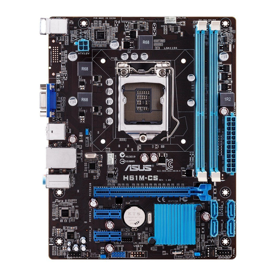
H61M-CS AUDIO PCIEX16 Super PCIEX1_1 BATTERY Intel ® PCIEX1_2 USB56 64Mb BIOS AAFP SPEAKER Connectors/Jumpers/Slots/LED Page 1. USB device wake-up (3-pin USBPW1-4, USBPW5-8) 2. ATX power connectors (24-pin EATXPWR, 4-pin ATX12V) 3. CPU and chassis fan connectors (4-pin CPU_FAN, 4-pin CHA_FAN) 4. Intel® LGA1155 CPU socket 5. DDR3 DIMM slots 6. Intel® H61 Serial ATA 3.0Gb/s connectors (7-pin SATA3G_1/2/3/4) 7. System panel connector (10-1 pin F_PANEL) 8. Speaker connector (4-pin SPEAKER) 9. Clear RTC RAM (3-pin CLRTC) 10. USB 2.0 connectors (10-1 pin USB56) 11. Front panel audio connector (10-1 pin AAFP) ASUS H61M-CS... -
Page 12: Central Processing Unit (Cpu)
Central Processing Unit (CPU) This motherboard comes with a surface mount LGA1150 socket designed for the Intel 4th/5th ® generation Core™ i7 / Core™ i5 / Core™ i3, Pentium ® , and Celeron ® processors. H61M-CS H61M-CS CPU socket LGA1155 Unplug all power cables before installing the CPU. • Upon purchase of the motherboard, ensure that the PnP cap is on the socket and the socket contacts are not bent. Contact your retailer immediately if the PnP cap is missing, or if you see any damage to the PnP cap/socket contacts/ motherboard components. ASUS will shoulder the cost of repair only if the damage is shipment/transit-related. • Keep the cap after installing the motherboard. ASUS will process Return Merchandise Authorization (RMA) requests only if the motherboard comes with the cap on the LGA1150 socket. • The product warranty does not cover damage to the socket contacts resulting from incorrect CPU installation/removal, or misplacement/loss/incorrect removal of the PnP cap. Chapter 1: Product introduction... - Page 13 1.4.1 Installing the CPU ASUS H61M-CS...
-
Page 14: Cpu Heatsink And Fan Assembly Installation
1.4.2 CPU heatsink and fan assembly installation Apply the Thermal Interface Material to the CPU heatsink and CPU before you install the heatsink and fan if necessary. To install the CPU heatsink and fan assembly Chapter 1: Product introduction... -
Page 15: System Memory
To uninstall the CPU heatsink and fan assembly System memory 1.5.1 Overview This motherboard comes with two Double Data Rate 3 (DDR3) Dual Inline Memory Modules (DIMM) sockets. A DDR3 module has the same physical dimensions as a DDR2 DIMM but is notched differently to prevent installation on a DDR2 DIMM socket. DDR3 modules are developed for better performance with less power consumption. Channel Sockets Channel A DIMM_A1 Channel B DIMM_B1 H61M-CS H61M-CS 240-pin DDR3 DIMM sockets ASUS H61M-CS... -
Page 16: Memory Configurations
1.5.2 Memory configurations You may install 1GB, 2GB, 4GB, and 8GB unbuffered non-ECC DDR3 DIMMs into the DIMM sockets. • You may install varying memory sizes in Channel A and Channel B. The system maps the total size of the lower-sized channel for the dual-channel configuration. Any excess memory from the higher-sized channel is then mapped for single-channel operation. • Always install DIMMs with the same CAS latency. For optimal compatibility, we recommend that you install memory modules of the same version or date code (D/C) from the same vendor. Check with the retailer to get the correct memory modules. • Memory module with memory frequency higher than 2133 MHz and its corresponding timing or the loaded XMP Profile is not the JEDEC memory standard. The stability and compatibility of these memory modules depend on the CPU's capabilities and other installed devices. • Due to the memory address limitation on 32-bit Windows OS, when you install ® 4GB or more memory on the motherboard, the actual usable memory for the OS can be about 3GB or less. For effective use of memory, we recommend that you do any of the following: - Use a maximum of 3GB system memory if you are using a 32-bit Windows OS. -
Page 17: Installing A Dimm
1.5.3 Installing a DIMM To install a DIMM To remove a DIMM ASUS H61M-CS... -
Page 18: Expansion Slots
Expansion slots In the future, you may need to install expansion cards. The following sub-sections describe the slots and the expansion cards that they support. Unplug the power cord before adding or removing expansion cards. Failure to do so may cause you physical injury and damage motherboard components. 1.6.1 Installing an expansion card To install an expansion card: Before installing the expansion card, read the documentation that came with it and make the necessary hardware settings for the card. Remove the system unit cover (if your motherboard is already installed in a chassis). - Page 19 USB2.0 controller 2 – – – – – – – shared HD audio – – – – – – shared – SATA controller 1 – – – shared – – – – SATA controller 2 – – – shared – – – – ASUS H61M-CS 1-11...
-
Page 20: Jumpers
This jumper allows you to clear the Real Time Clock (RTC) RAM in CMOS. You can clear the CMOS memory of date, time, and system setup parameters by erasing the CMOS RTC RAM data. The onboard button cell battery powers the RAM data in CMOS, which include system setup information such as system passwords. CLRTC H61M-CS Normal Clear RTC (Default) H61M-CS Clear RTC RAM To erase the RTC RAM: Turn OFF the computer and unplug the power cord. Move the jumper cap from pins 1-2 (default) to pins 2-3. Keep the cap on pins 2-3 for about 5-10 seconds, then move the cap back to pins 1-2. Plug the power cord and turn ON the computer. Hold down the <Del> key during the boot process and enter BIOS setup to re-enter data. Except when clearing the RTC RAM, never remove the cap on CLRTC jumper default position. Removing the cap will cause system boot failure! -
Page 21: Connectors
10Mbps connection ORANGE Linked ORANGE 100Mbps LAN port connection BLINKING Data activity GREEN 1Gbps connection Line In port (light blue). This port connects to the tape, CD, DVD player, or other audio sources. Line Out port (lime). This port connects to a headphone or a speaker. In the 4, 6, and 8-channel configurations, the function of this port becomes Front Speaker Out. Microphone port (pink). This port connects to a microphone. Refer to the audio configuration table for the function of the audio ports in 2, 4, 6, or 8-channel configuration. ASUS H61M-CS 1-13... - Page 22 Audio 2, 4, 6, or 8-channel configuration Headset Port 4-channel 6-channel 8-channel 2-channel Light Blue (Rear Line In Rear Speaker Out Rear Speaker Out Rear Speaker Out panel) Front Speaker Front Speaker Front Speaker Lime (Rear panel) Line Out Pink (Rear panel) Mic In Mic In Bass/Center Bass/Center Lime (Front panel) – – – Side Speaker Out To configure an 8-channel audio output: • Use a chassis with HD audio module in the front panel to support an 8-channel audio output. USB 2.0 ports. These 4-pin Universal Serial Bus (USB) ports are for USB 2.0/1.1 devices.
-
Page 23: Internal Connectors
AAFP PIN 1 PIN 1 H61M-CS HD-audio-compliant Legacy AC’97 pin definition compliant definition H61M-CS Front panel audio connector • We recommend that you connect a high-definition front panel audio module to this connector to avail of the motherboard’s high-definition audio capability. • If you want to connect a high-definition front panel audio module to this connector, set the Front Panel Type item in the BIOS setup to [HD]. If you want to connect an AC'97 front panel audio module to this connector, set the item to [AC97]. By default, this connector is set to [HD]. See section 2.5.6 Onboard Devices Configuration for details. - Page 24 Power OK -5 Volts PIN 1 +5 Volts +5 Volts PSON# H61M-CS +3 Volts -12 Volts +3 Volts +3 Volts PIN 1 H61M-CS ATX power connectors • For a fully configured system, we recommend that you use a power supply unit (PSU) that complies with ATX 12 V Specification 2.0 (or later version) and provides a minimum power of 350 W. • DO NOT forget to connect the 4-pin ATX +12V power plug. Otherwise, the system will not boot up. • We recommend that you use a PSU with higher power output when configuring a system with more power-consuming devices. The system may become unstable or may not boot up if the power is inadequate.
- Page 25 RSATA_RXN2 RSATA_TXN1 RSATA_TXN2 RSATA_RXN1 RSATA_TXP2 RSATA_RXP1 SATA3G_4 SATA3G_3 H61M-CS RSATA_RXP4 RSATA_TXP3 RSATA_RXN4 RSATA_TXN3 RSATA_TXN4 RSATA_RXN3 RSATA_TXP4 RSATA_RXP3 H61M-CS Intel SATA 3.0Gb/s connectors ® • You must install Windows XP Service Pack 3 or later version before using Serial ® ATA hard disk drives. • Due to H61 Chipset limitation, AHCI Mode only works on Windows Vista / ® Windows 7. Please use IDE Mode on Windows XP. ® ® To configure the SATA type in BIOS, click Advanced Mode > Advanced tab •...
- Page 26 USB device wake-up (3-pin PS2_USBPW1~4; USBPW5~8) Set this jumper to +5V to wake up the computer from S1 sleep mode (CPU stopped, DRAM refreshed, system running in low power mode) using the connected USB devices. Set to +5VSB to wake up from S3 and S4 sleep modes (no power to CPU, DRAM in slow refresh, power supply in reduced power mode). USBPW1-4 +5VSB (Default) USBPW5-8 H61M-CS +5VSB (Default) H61M-CS USB Device Wake Up • The USB device wake-up feature requires a power supply that can provide 500mA on the +5VSB lead for each USB port; otherwise, the system would not power up. • The total current consumed must NOT exceed the power supply capability (+5VSB) whether under normal condition or in sleep mode. Chapter 1: Product introduction 1-18...
- Page 27 CPU and chassis fan connectors (4-pin CPU_FAN, 4-pin CHA_FAN) Connect the fan cables to the fan connectors on the motherboard, ensuring that the black wire of each cable matches the ground pin of the connector. CPU_FAN H61M-CS H61M-CS CPU fan connector Do not forget to connect the fan cables to the fan connectors. Insufficient air flow inside the system may damage the motherboard components. These are not jumpers! Do not place jumper caps on the fan connectors! •...
- Page 28 USB connectors (10-1 pin USB56) This connector is for USB 2.0 port. Connect the USB module cable to this connector, then install the module to a slot opening at the back of the system chassis. This USB connector complies with USB 2.0 specification that supports up to 480 Mbps connection speed. USB56 H61M-CS PIN 1 H61M-CS USB2.0 connectors Never connect a 1394 cable to the USB connectors. Doing so will damage the motherboard! The USB module cable is purchased separately. Chapter 1: Product introduction 1-20...
-
Page 29: System Panel Connector
System panel connector (10-1 pin F_PANEL) This connector supports several chassis-mounted functions. F_PANEL +PWR LED PWR BTN PIN 1 H61M-CS +HDD_LED RESET H61M-CS System panel connector • System power LED (2-pin +PWR_LED-) This 2-pin connector is for the system power LED. Connect the chassis power LED cable to this connector. The system power LED lights up when you turn on the system power, and blinks when the system is in sleep mode. • Hard disk drive activity LED (2-pin +HDD_LED-) This 2-pin connector is for the HDD Activity LED. Connect the HDD Activity LED cable to this connector. The IDE LED lights up or flashes when data is read from or written to the HDD. • Power/Soft-off button (2-pin PWR_BTN) This 2-pin connector is for the system power button. -
Page 30: Software Support
® Vista Service Pack 1 or later versions before installing the drivers for better compatibility and system stability. 1.9.2 Support DVD information The Support DVD that comes with the motherboard package contains the drivers, software applications, and utilities that you can install to avail all motherboard features. The contents of the Support DVD are subject to change at any time without notice. Visit the ASUS website at www.asus.com for updates. To run the Support DVD Place the Support DVD into the optical drive. If Autorun is enabled in your computer, the DVD automatically displays the Specials screen. Click Drivers, Utilities, Make Disk, Manual, and Contact tabs to display their respective menus. The following screen is for reference only. Click an icon to display Support DVD/ motherboard information... -
Page 31: Managing And Updating Your Bios
BIOS in the future. Copy the original motherboard BIOS using the ASUS Update utility. 2.1.1 ASUS Update utility The ASUS Update is a utility that allows you to manage, save, and update the motherboard BIOS in Windows environment. ®... -
Page 32: Bios Setup Program
2.1.2 ASUS EZ Flash 2 The ASUS EZ Flash 2 feature allows you to update the BIOS without using an OS-based utility. Before you start using this utility, download the latest BIOS file from the ASUS website at www. asus.com. -
Page 33: Asus Crashfree Bios 3 Utility
ASUS CrashFree BIOS 3 utility The ASUS CrashFree BIOS 3 is an auto recovery tool that allows you to restore the BIOS file when it fails or gets corrupted during the updating process. You can restore a corrupted BIOS file using the motherboard support DVD or a USB flash drive that contains the updated BIOS file. -
Page 34: Asus Bios Updater
Booting the system in DOS environment Insert the USB flash drive with the latest BIOS file and BIOS Updater to the USB port. Boot your computer. When the ASUS Logo appears, press <F8> to show the BIOS Boot Device Select Menu. Insert the support DVD into the optical drive and select the optical drive as the boot device. - Page 35 BIOS update. Select Yes and press <Enter>. When BIOS update is done, press <ESC> to exit BIOS Updater. Restart your computer. DO NOT shut down or reset the system while updating the BIOS to prevent system boot failure!. • For BIOS Updater version 1.30 or later, the utility automatically exits to the DOS prompt after updating BIOS. • Ensure to load the BIOS default settings to ensure system compatibility and stability. Select the Load Optimized Defaults item under the Exit menu. Refer to section 2.9 Exit menu for details. • Ensure to connect all SATA hard disk drives after updating the BIOS file if you have disconnected them. ASUS H61M-CS...
-
Page 36: Bios Setup Program
We recommend to always shut down the system properly from the operating system. • The BIOS setup screens shown in this section are for reference purposes only, and may not exactly match what you see on your screen. • Visit the ASUS website at www.asus.com to download the latest BIOS file for this motherboard. • Ensure that a USB mouse is connected to your motherboard if you want to use the mouse to control the BIOS setup program. •... - Page 37 Displays the system properties Selects the Selects the boot device priority of the selected mode on the right Advanced mode hand side functions • The boot device options vary depending on the devices you installed to the system. • The Boot Menu(F8) button is available only when the boot device is installed to the system. ASUS H61M-CS...
-
Page 38: Advanced Mode
The Advanced Mode provides advanced options for experienced end-users to configure the BIOS settings. The figure below shows an example of the Advanced Mode. Refer to the following sections for the detailed configurations. To access the EZ Mode, click Exit, then select ASUS EZ Mode. Back button Menu items... -
Page 39: Main Menu
You cannot select an item that is not user-configurable. A configurable field is highlighted when selected. To change the value of a field, select it and press <Enter> to display a list of options. ASUS H61M-CS... -
Page 40: Main Menu
Main menu The Main menu screen appears when you enter the Advanced Mode of the BIOS Setup program. The Main menu provides you an overview of the basic system information, and allows you to set the system date, time, language, and security settings. 2.3.1 System Language [English] Allows you to choose the BIOS language version from the options. -
Page 41: Administrator Password
To clear the user password, follow the same steps as in changing a user password, but press <Enter> when prompted to create/confirm the password. After you clear the password, the User Password item on top of the screen shows Not Installed. ASUS H61M-CS 2-11... -
Page 42: Ai Tweaker Menu
Ai Tweaker menu The Ai Tweaker menu items allow you to configure overclocking-related items. Be cautious when changing the settings of the Ai Tweaker menu items. Incorrect field values can cause the system to malfunction. The configuration options for this section vary depending on the CPU and DIMM model you installed on the motherboard. Target CPU Speed : xxxxMHz Displays the target CPU Turbo-Mode speed. -
Page 43: Dram Timing Control
Allows you to maintain the turbo ratio’s long duration power. Use the <+> and <-> keys to adjust the value. Short Duration Power Limit [Auto] Allows you to limit the turbo ratio’s long duration power. Use the <+> and <-> keys to adjust the value. Primary Plane Current Limit [Auto] Maximum instantaneous current allowed at any given time for CPU cores. Use <+> and <-> key to adjust the value at 0.125A increment. ASUS H61M-CS 2-13... -
Page 44: Advanced Menu
Secondary Plane Current Limit [Auto] Maximum instantaneous current allowed at any given time for Internal Graphics cores. Use <+> and <-> key to adjust the value at 0.125A increment. Advanced menu The Advanced menu items allow you to change the settings for the CPU and other system devices. Be cautious when changing the settings of the Advanced menu items. Incorrect field values can cause the system to malfunction. -
Page 45: Cpu Power Management Configuration
CPU C3 Report [Auto] Allows you to disable or enable the CPU C3 report to OS. [Auto] Set this item automatically. [Disabled] Disables this function. [Enabled] Enables the C3 report function. This item should be enabled in order to enable the Enhanced Halt State. ASUS H61M-CS 2-15... -
Page 46: Pch Configuration
CPU C6 Report [Auto] Allows you to disable or enable the CPU C6 report to OS. [Auto] Set this item automatically. [Disabled] Disables this function. [Enabled] Enables the C6 report function. This item should be enabled in order to enable the Enhanced Halt State. 2.5.2 PCH Configuration High Precision Timer [Enabled] Allows you to enable or disable the High Precision Event Timer. -
Page 47: Sata Configuration
Allow you to enable remapping the memory above 4GB. [Disabled] Disables this function. Graphics Configuration Primary Display [Auto] Allows you to decide which graphics controller to use as the primary boot device. Configuration options: [Auto] [iGPU] [PCIE] iGPU Memory [Auto] Allows you to select the amount of system memory allocated to DVMT 5.0 used by the iGPU. Configuration options: [Auto] [32M]~[1024M] ASUS H61M-CS 2-17... -
Page 48: Usb Configuration
Render Standby [Enabled] Allows you to enable the Intel Graphics Render Standby support to reduce the iGPU power ® use when idle. Configuration options: [Disabled] [Enabled] iGPU Multi-Monitor [Disabled] Allows you to enable the iGPU Multi-Monitor. For Lucid Virtu MVP function supports, set this item to [Enabled] to empower both integrated and discrete graphics. iGPU shared system memory size is fixed in 64MB. Configuration options: [Disabled] [Enabled] 2.5.5 USB Configuration... -
Page 49: Onboard Devices Configuration
This item appears only when you set the previous item to [Enabled] and allows you to select RTC alarm time (days). When you set the time to zero, the RTC alarms everyday. Use <+> and <-> keys to adjust the time. ASUS H61M-CS 2-19... -
Page 50: Monitor Menu
- Hour / - Minute / - Second Allows you to set the RTC alarm time. Use <+> and <-> keys to adjust the time. 2.5.8 Network Stack Network Stack [Disabled] This item allows user to disable or enable the UEFI network stack. Configuration options: [Disabled] [Enabled] The following two items appear only when you set the previous item to [Enabled]. Ipv4 PXE Support [Enabled] This item allows user to disable or enable the Ipv4 PXE Boot support. Configuration options: [Disabled] [Enable] Ipv6 PXE Support [Enabled]... - Page 51 CPU Fan Max. Duty Cycle(%) [100] Use the <+> and <-> keys to adjust the maximum CPU fan duty cycle. The values range from 20% to 100%. When the CPU temperature reaches the upper limit, the CPU fan will operate at the maximum duty cycle. CPU Lower Temperature [20] Displays the lower limit of the CPU temperature. CPU Fan Min. Duty Cycle(%) [20] Use the <+> and <-> keys to adjust the minimum CPU fan duty cycle. The values range from 0% to 100%. When the CPU temperature is under 40ºC, the CPU fan will operate at the minimum duty cycle. ASUS H61M-CS 2-21...
- Page 52 2.6.5 Chassis Q-Fan Control [Enabled] [Disabled] Disables the Chassis Q-Fan control feature. [Enabled] Enables the Chassis Q-Fan control feature. Chassis Fan Speed Low Limit [600 RPM] This item appears only when you enable the Chassis Q-Fan Control feature and allows you to disable or set the chassis fan warning speed. Configuration options: [Ignore] [200RPM] [300 RPM] [400 RPM] [500 RPM] [600 RPM] Chassis Fan Profile [Standard] This item appears only when you enable the Chassis Q-Fan Control feature and allows you to set the appropriate performance level of the chassis fan.
-
Page 53: Boot Menu
POST time. [Full Initialization] All USB devices will be available during POST. This process will extend the POST time. [Partial Initialization] For a faster POST time, only the USB ports with keyboard and mouse connections will be detected. ASUS H61M-CS 2-23... - Page 54 Enables the full screen logo display feature. [Disabled] Disables the full screen logo display feature. Set this item to [Enabled] to use the ASUS MyLogo 2™ feature. POST Delay Time [3 sec] This item appears only when you set Full Screen Logo to [Enabled]. This item allows you to select the desired additional POST waiting time to easily enter the BIOS setup.
- Page 55 [Both, Legacy OpROM first] [Both, UEFI first] [Legacy OpROM first] [UEFI driver first] [Ignore] Boot from PCIe/PCI Expansion Devices [Legacy OpROM first] Allows you to select the type of PCIe/PCI expansion devices that you want to launch. Configuration options: [Legacy OpROM first] [UEFI driver first] ASUS H61M-CS 2-25...
-
Page 56: Secure Boot
2.7.9 Secure Boot Allows you to configure the Windows Secure Boot settings and manage its keys to protect the ® system from unauthorized access and malwares during POST. OS Type [Other OS] Allows you to select your installed operating system. [Windows UEFI mode] Executes the Microsoft Secure Boot check. - Page 57 Allows you to load the downloaded dbx from a USB storage device. Copy DBX from file Allows you to store the dbx to a USB storage device. Delete the DBX Allows you to delete the dbx file from your system. Configuration options: [Yes] [No] ASUS H61M-CS 2-27...
-
Page 58: Tools Menu
<Enter> to display the submenu. 2.8.1 ASUS EZ Flash 2 Utility Allows you to run ASUS EZ Flash 2. Press [Enter] to launch the ASUS EZ Flash 2 screen. For more details, see section 2.1.2 ASUS EZ Flash 2. 2.8.2... -
Page 59: Exit Menu
Discard Changes & Exit This option allows you to exit the Setup program without saving your changes. When you select this option or if you press <Esc>, a confirmation window appears. Select Yes to discard changes and exit. ASUS H61M-CS 2-29... - Page 60 ASUS EZ Mode This option allows you to enter the EZ Mode screen. Launch EFI Shell from filesystem device This option allows you to attempt to launch the EFI Shell application (shellx64.efi) from one of the available devices that have a filesystem.
-
Page 61: Appendices
Appendices Notices Federal Communications Commission Statement This device complies with Part 15 of the FCC Rules. Operation is subject to the following two conditions: • This device may not cause harmful interference. • This device must accept any interference received including interference that may cause undesired operation. -
Page 62: Canadian Department Of Communications Statement
ASUS Recycling/Takeback Services ASUS recycling and takeback programs come from our commitment to the highest standards for protecting our environment. We believe in providing solutions for you to be able to responsibly recycle our products, batteries, other components as well as the packaging materials. -
Page 63: Asus Contact Information
+1-510-739-3777 +1-510-608-4555 Web site http://usa.asus.com Technical Support Support fax +1-812-284-0883 General support +1-812-282-2787 Online support http://support.asus.com/techserv/techserv.aspx ASUS COMPUTER GmbH (Germany and Austria) Address Harkort Str. 21-23, D-40880 Ratingen, Germany +49-2102-959931 Web site http://www.asus.com/de Online contact http://eu-rma.asus.com/sales Technical Support Telephone +49-2102-5789555... - Page 64 Appendices...
Need help?
Do you have a question about the H61M-CS and is the answer not in the manual?
Questions and answers