Table of Contents
Advertisement
Quick Links
Advertisement
Table of Contents

Subscribe to Our Youtube Channel
Related Manuals for Asus H61M-C


Summary of Contents for Asus H61M-C
- Page 1 H61M-C...
- Page 2 Product warranty or service will not be extended if: (1) the product is repaired, modified or altered, unless such repair, modification of alteration is authorized in writing by ASUS; or (2) the serial number of the product is defaced or missing.
-
Page 3: Table Of Contents
Contents Safety information ...................... vi About this guide ......................vii H61M-C specifications summary ................ix Package contents ....................... xi Chapter 1: Product introduction Special features .................... 1-1 1.1.1 Product highlights ................1-1 1.1.2 ASUS Exclusive Features ............... 1-2 Before you proceed ..................1-4 Motherboard overview ................. - Page 4 CSM (Compatibility Support Module) ..........2-25 2.7.9 Security Boot ................. 2-26 2.7.10 Boot Option Priorities ..............2-29 2.7.11 Boot Override ................2-29 Tools menu ....................2-30 2.8.1 ASUS EZ Flash 2 Utility ..............2-30 2.8.2 ASUS SPD Information ..............2-30...
- Page 5 2.8.3 ASUS O.C. Profile ................. 2-30 Exit menu ....................2-31 Appendices Notices ........................A-1 ASUS contact information ..................A-3...
-
Page 6: Safety Information
Safety information Electrical safety • To prevent electrical shock hazard, disconnect the power cable from the electrical outlet before relocating the system. • When adding or removing devices to or from the system, ensure that the power cables for the devices are unplugged before the signal cables are connected. If possible, disconnect all power cables from the existing system before you add a device. -
Page 7: About This Guide
Refer to the following sources for additional information and for product and software updates. ASUS websites The ASUS website provides updated information on ASUS hardware and software products. Refer to the ASUS contact information. Optional documentation Your product package may include optional documentation, such as warranty flyers, that may have been added by your dealer. -
Page 8: Conventions Used In This Guide
Conventions used in this guide To ensure that you perform certain tasks properly, take note of the following symbols used throughout this manual. DANGER/WARNING: Information to prevent injury to yourself when trying to complete a task. CAUTION: Information to prevent damage to the components when trying to complete a task IMPORTANT: Instructions that you MUST follow to complete a task. -
Page 9: H61M-C Specifications Summary
DDR3 1600 MHz and higher memory frequency is supported by Intel • ® 3rd generation processors. Refer to www.asus.com for the latest Memory QVL (Qualified Vendors • List). When you install a total memory of 4GB capacity or more, Windows •... - Page 10 BIOS features 64 Mb Flash ROM, UEFI BIOS, PnP, DMI v2.0, WfM 2.0, ACPI v2.0a, SM BIOS v2.7, SLP 3.0, Multi-language BIOS, ASUS EZ Flash 2, ASUS CrashFree BIOS 3, F12 PrintScreen function, F3 Shortcut function, and ASUS DRAM SPD (Serial Presence Detect) memory information...
-
Page 11: Package Contents
SATA3G_4 SATA3G_3 USB56 SPDIF_OUT USB78 USB910 SPEAKER AAFP ASUS H61M-C motherboard 2 x Serial ATA 3 Gb/s cables 1 x I/O Shield User Guide Support DVD • If any of the above items is damaged or missing, contact your retailer. -
Page 13: Chapter 1: Product Introduction
1.0 and PCIe 2.0 devices. PCIe 3.0 will become a must-have feature for users who wish to improve and optimize graphic performance, as well as have the latest technology available to them. ® * PCI 3.0 speed is supported by Intel 3rd generation Core™ processors. ASUS H61M-C... -
Page 14: Asus Exclusive Features
ASUS Exclusive Features ASUS UEFI BIOS ASUS UEFI BIOS, a UEFI compliant architecture, offers the first mouse-controlled intuitive graphical BIOS interface that goes beyond the traditional keyboard-only BIOS controls, providing you with more flexibility, convenience, and easy to navigate EFI BIOS than the traditional BIOS versions. -
Page 15: Asus Mylogo2
DVD or a USB flash disk that contains the BIOS file. ASUS EZ Flash 2 ASUS EZ Flash 2 is a user-friendly utility that allows you to update the BIOS without using a bootable floppy disk or an OS-based utility. -
Page 16: Before You Proceed
ON, in sleep mode, or in soft-off mode. This is a reminder that you should shut down the system and unplug the power cable before removing or plugging in any motherboard component. The illustration below shows the location of the onboard LED. SB_PWR H61M-C Standby Power Powered Off H61M-C Onboard LED Chapter 1: Product introduction... -
Page 17: Motherboard Overview
Screw holes Place six screws into the holes indicated by circles to secure the motherboard to the chassis. DO NOT overtighten the screws! Doing so can damage the motherboard. Place this side towards the rear of the chassis H61M-C ASUS H61M-C... -
Page 18: Motherboard Layout
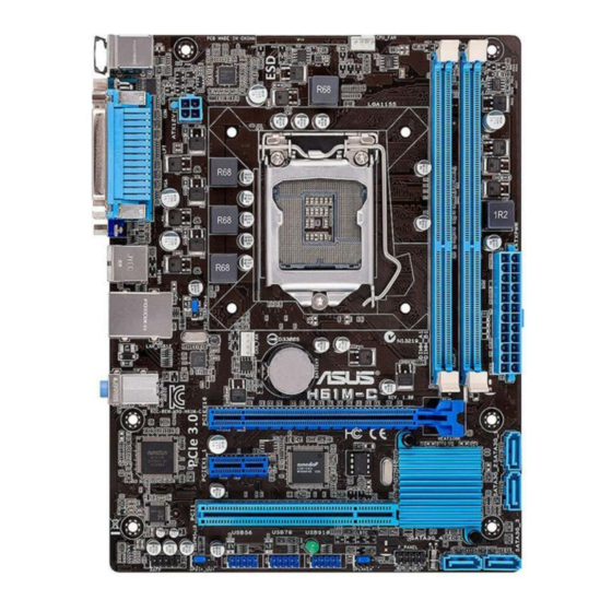
1.3.3 Motherboard layout 17.8cm(7.0in) KBMS CPU_FAN 8876 ATX12V USB34 LAN_USB12 CHA_FAN 8111F BATTERY AUDIO H61M-C PCIEX16 Super 64Mb PCIEX1_1 BIOS 1083 Intel ® PCI1 SB_PWR F_PANEL SATA3G_4 SATA3G_3 USB56 USB78 USB910 SPDIF_OUT SPEAKER AAFP 13 12 10 9 Chapter 1: Product introduction... -
Page 19: Layout Contents
Contact your retailer immediately if the PnP cap is missing, or if you see any damage to the PnP cap/socket contacts/motherboard components. ASUS will shoulder the cost of repair only if the damage is shipment/ transit-related. -
Page 20: Cpu Installation
1.4.1 CPU installation The LGA1156 CPU is not compatible with the LGA1155 socket. DO NOT install an LGA1156 CPU on the LGA1155 socket. Chapter 1: Product introduction... - Page 21 ASUS H61M-C...
-
Page 22: Cpu Heatsink And Fan Assembly Installation
1.4.2 CPU heatsink and fan assembly installation Apply the Thermal Interface Material to the CPU heatsink and CPU before you install the heatsink and fan if necessary. To install the CPU heatsink and fan assembly Chapter 1: Product introduction 1-10... - Page 23 To uninstall the CPU heatsink and fan assembly ASUS H61M-C 1-11...
-
Page 24: System Memory
Sockets Channel A DIMM_A1 H61M-C Channel B DIMM_B1 H61M-C 240-pin DDR3 DIMM sockets 1.5.2 Memory configurations You may install 1GB, 2GB, 4GB, and 8GB unbuffered non-ECC DDR3 DIMMs into the DIMM sockets. • You may install varying memory sizes in Channel A and Channel B. The system maps the total size of the lower-sized channel for the dual-channel configuration. -
Page 25: Installing A Dimm
2.4 Ai Tweaker menu for manual memory frequency adjustment. • For system stability, use a more efficient memory cooling system to support a full memory load (2 DIMMs) or overclocking condition. 1.5.3 Installing a DIMM ASUS H61M-C 1-13... -
Page 26: Expansion Slots
To remove a DIMM Expansion slots In the future, you may need to install expansion cards. The following sub-sections describe the slots and the expansion cards that they support. Unplug the power cord before adding or removing expansion cards. Failure to do so may cause you physical injury and damage motherboard components. -
Page 27: Configuring An Expansion Card
– – – – shared HD audio – – – – – – shared – SATA controller 1 – – – shared – – – – SATA controller 2 – – – shared – – – – ASUS H61M-C 1-15... -
Page 28: Jumpers
H61M-C Normal Clear RTC (Default) H61M-C Clear RTC RAM To erase the RTC RAM: Turn OFF the computer and unplug the power cord. Move the jumper cap from pins 1-2 (default) to pins 2-3. Keep the cap on pins 2-3 for about 5~10 seconds, then move the cap back to pins 1-2. - Page 29 H61M-C +5VSB (Default) H61M-C PS2/USB device wake-up USB device wake-up (3-pin USBPW5~10) Set this jumper to +5V to wake up the computer from S1 sleep mode (CPU stopped, DRAM refreshed, system running in low power mode) using the connected USB devices.
-
Page 30: Connectors
Connectors 1.8.1 Rear panel ports PS/2 Mouse port. This port connects to a PS/2 mouse. Parallel port. This 25-pin port connects a parallel printer, a scanner, or other devices. LAN (RJ-45) port. This port allows Gigabit connection to a Local Area Network (LAN) through a network hub. -
Page 31: Internal Connectors
H61M-C HD-audio-compliant Legacy AC’97 pin definition compliant definition H61M-C Front panel audio connector • We recommend that you connect a high-definition front panel audio module to this connector to avail of the motherboard’s high-definition audio capability. • If you want to connect a high-definition front panel audio module to this connector, set the Front Panel Type item in the BIOS setup to [HD]. - Page 32 • If you are uncertain about the minimum power supply requirement for your system, refer to the Recommended Power Supply Wattage Calculator at http://support.asus. com/PowerSupplyCalculator/PSCalculator.aspx?SLanguage=en-us for details. Chapter 1: Product introduction...
- Page 33 This connector is for an additional Sony/Philips Digital Interface (S/PDIF) port. Connect the S/PDIF Out module cable to this connector, then install the module to a slot opening at the back of the system chassis. H61M-C SPDIF_OUT H61M-C Digital audio connector The S/PDIF module is purchased separately. ASUS H61M-C 1-21...
- Page 34 The two fan connectors support fans of maximum 2A (24 W) fan power. • Only the 4-pin CPU fan and 4-pin chassis fan support the ASUS Fan Xpert feature. USB connectors (10-1 pin USB56, USB78, USB910) These connectors are for USB 2.0 ports. Connect the USB module cable to any of these connectors, then install the module to a slot opening at the back of the system chassis.
-
Page 35: System Panel Connector
PIN 1 H61M-C +HD_LED- RESET H61M-C System panel connector • System power LED (2-pin +PWR_LED-) This 2-pin connector is for the system power LED. Connect the chassis power LED cable to this connector. The system power LED lights up when you turn on the system power, and blinks when the system is in sleep mode. -
Page 36: Software Support
The contents of the Support DVD are subject to change at any time without notice. Visit the ASUS website at www.asus.com for updates. To run the Support DVD Place the Support DVD into the optical drive. -
Page 37: Chapter 2: Bios Information
Managing and updating your BIOS Save a copy of the original motherboard BIOS file to a USB flash disk in case you need to restore the BIOS in the future. Copy the original motherboard BIOS using the ASUS Update utility. -
Page 38: Asus Ez Flash
2.1.3 ASUS CrashFree BIOS 3 utility The ASUS CrashFree BIOS 3 is an auto recovery tool that allows you to restore the BIOS file when it fails or gets corrupted during the updating process. You can restore a corrupted BIOS file using the motherboard support DVD or a USB flash drive that contains the updated BIOS file. -
Page 39: Recovering The Bios
2.1.4 ASUS BIOS Updater The ASUS BIOS Updater allows you to update BIOS in DOS environment. This utility also allows you to copy the current BIOS file that you can use as a backup when the BIOS fails or gets corrupted during the updating process. -
Page 40: Updating The Bios File
To update the BIOS file using BIOS Updater: At the FreeDOS prompt, type bupdater /pc /g and press <Enter>. The BIOS Updater screen appears as below. ASUSTek BIOS Updater for DOS V1.30 Current ROM Update ROM BOARD: H61M-C BOARD: Unknown VER: 0205 VER: Unknown... -
Page 41: Bios Setup Program
The BIOS setup screens shown in this section are for reference purposes only, and may not exactly match what you see on your screen. Visit the ASUS website at www.asus.com to download the latest BIOS file for this • motherboard. - Page 42 EZ Mode By default, the EZ Mode screen appears when you enter the BIOS setup program. The EZ Mode provides you an overview of the basic system information, and allows you to select the display language, system performance mode and boot device priority. To access the Advanced Mode, click Exit/Advanced Mode, then select Advanced Mode or press F7 hot key for the advanced BIOS settings.
-
Page 43: Advanced Mode
The Advanced Mode provides advanced options for experienced end-users to configure the BIOS settings. The figure below shows an example of the Advanced Mode. Refer to the following sections for the detailed configurations. To access the EZ Mode, click Exit, then select ASUS EZ Mode. Back button Menu items... -
Page 44: Menu Items
Menu items The highlighted item on the menu bar displays the specific items for that menu. For example, selecting Main shows the Main menu items. The other items (Ai Tweaker, Advanced, Monitor, Boot, Tool, and Exit) on the menu bar have their respective menu items. -
Page 45: Main Menu
RAM to clear the BIOS password. See section 1.7 Jumpers for information on how to erase the RTC RAM. The Administrator or User Password items on top of the screen show the default • Not Installed. After you set a password, these items show Installed. ASUS H61M-C... -
Page 46: Administrator Password
Administrator Password If you have set an administrator password, we recommend that you enter the administrator password for accessing the system. Otherwise, you might be able to see or change only selected fields in the BIOS setup program. To set an administrator password: Select the Administrator Password item and press <Enter>. -
Page 47: Ai Tweaker Menu
800MHz] [DDR3-1066MHz] [DDR3-1333MHz] [DDR3-1600MHz] [DDR3-1866MHz] [DDR3- 2133MHz] [DDR3-2400MHz] The configuration options vary with the CPU types installed on the system. Selecting a very high memory frequency may cause the system to become unstable! If this happens, revert to the default setting. ASUS H61M-C 2-11... -
Page 48: Dram Timing Control
2.4.2 DRAM Timing Control The sub-items in this menu allow you to set the DRAM timing control features. Use the <+> and <-> keys to adjust the value. To restore the default setting, type [auto] using the keyboard and press <Enter>. Changing the values in this menu may cause the system to become unstable! If this happens, revert to the default settings. -
Page 49: Advanced Menu
Allows you to choose the number of CPU cores to activate in each processor package. Configuration options: [All] [1] [2] [3] Limit CPUID Maximum [Disabled] [Enabled] Allows legacy operating systems to boot even without support for CPUs with extended CPUID functions. [Disabled] Disables this function. ASUS H61M-C 2-13... - Page 50 Execute Disable Bit [Enabled] [Enabled] Enables the No-Execution Page Protection Technology. [Disabled] Forces the XD feature flag to always return to zero (0). Intel Virtualization Technology [Disabled] [Enabled] Allows a hardware platform to run multiple operating systems separately and simultaneously, enabling one system to virtually function as several systems.
-
Page 51: Pch Configuration
S3 entry. Key in the desired value using the numeric keypad. Intel(R) Smart Connect Technology ISCT Configuration [Disabled] Allows you to enable or disable the ISCT configuration. Configuration options: [Enabled] [Disabled] ASUS H61M-C 2-15... -
Page 52: Sata Configuration
2.5.3 SATA Configuration While entering Setup, the BIOS automatically detects the presence of SATA devices. The SATA Port items show Not Present if no SATA device is installed to the corresponding SATA port. SATA Mode Selection [AHCI] Allows you to set the SATA configuration. [Disabled] Disables the SATA function. -
Page 53: Usb Configuration
Motherboard layout in this user manual for the locations of the USB ports. The USB port numbers may not be arranged in a consecutive order. 2.5.6 Onboard Devices Configuration HD Audio Controller [Enabled] [Enabled] Enables the High Definition Audio Controller. [Disabled] Disables the controller. ASUS H61M-C 2-17... -
Page 54: Serial Port Configuration
The following two items appear only when you set the HD Audio Controller item to [Enabled]. Front Panel Type [HD] Allows you to set the front panel audio connector (AAFP) mode to legacy AC’97 or high- definition audio depending on the audio standard that the front panel audio module supports. [HD] Sets the front panel audio connector (AAFP) mode to high definition audio. -
Page 55: Apm
The following two items appear only when you set the previous item to [Enabled]. Ipv4/ Ipv6 PXE Support [Enabled] This item allows user to disable or enable the Ipv4/ Ipv6 PXE Boot support. Configuration options: [Disabled] [Enable] ASUS H61M-C 2-19... -
Page 56: Monitor Menu
Monitor menu The Monitor menu displays the system temperature/power status, and allows you to change the fan settings. Scroll down to display the following items: 2.6.1 CPU Temperature / MB Temperature [xxxºC/xxxºF] The onboard hardware monitor automatically detects and displays the CPU and motherboard temperatures. -
Page 57: Cpu Voltage, 3.3V Voltage, 5V Voltage, 12V Voltage
This item appears only when you enable the Chassis Q-Fan Control feature and allows you to set the low limit warning for Chassis Fan speed. Configuration options: [Ignore] [200RPM] [300 RPM] [400 RPM] [500 RPM] [600 RPM] ASUS H61M-C 2-21... -
Page 58: Anti Surge Support [Disabled]
Chassis Fan Profile [Standard] This item appears only when you enable the Chassis Q-Fan Control feature and allows you to set the appropriate performance level of the chassis fan. [Standard] Sets to [Standard] to make the chassis fan automatically adjust depending on the chassis temperature. -
Page 59: Boot Menu
Boot menu The Boot menu items allow you to change the system boot options. Scroll down to display the following items: ASUS H61M-C 2-23... -
Page 60: Fast Boot [Enabled]
Accelerates the boot speed on the next boot after AC power loss. 2.7.2 Full Screen Logo [Enabled] [Enabled] Enables the full screen logo display feature. [Disabled] Disables the full screen logo display feature. Set this item to [Enabled] to use the ASUS MyLogo 2™ feature. Chapter 2: Getting started 2-24... -
Page 61: Bootup Numlock State [On]
[Enabled] For better compatibility, enable the CSM to fully support the non-UEFI driver add-on devices or the Windows UEFI mode. ® [Disabled] Disable the CSM to fully support the Windows Security Update and ® Security Boot. ASUS H61M-C 2-25... -
Page 62: Security Boot
The following four items appear when you set Launch CSM to [Enabled]. Boot Devices Control [UEFI and Legacy OpROM] Allows you to select the type of devices that you want to boot up. Configuration options: [UEFI and Legacy OpROM] [Legacy OpROM only] [UEFI only] Boot from Network Devices [Legacy OpROM first] Allows you to select the type of network devices that you want to launch. -
Page 63: Key Management
Allows you to load the downloaded KEK from a USB storage device. Copy KEK to File Allows you to store the KEK to a USB storage device. Delete the KEK Allows you to delete the KEK from your system. Configuration options: [Yes] [No] ASUS H61M-C 2-27... - Page 64 Append KEK from file Allows you to load the additional KEK from a storage device for an additional db and dbx loaded management. The KEK file must be formatted as a UEFI variable structure with time-based authenticated variable. DB Management The DB (Authorized Signature database) lists the signers or images of UEFI applications, operating system loaders, and UEFI drivers that you can load on the single computer.
-
Page 65: Boot Option Priorities
• To select the boot device during system startup, press <F8> when ASUS Logo appears. • To access Windows OS in Safe Mode, press <F8> after POST. -
Page 66: Tools Menu
<Enter> to display the submenu. 2.8.1 ASUS EZ Flash 2 Utility Allows you to run ASUS EZ Flash 2. Press [Enter] to launch the ASUS EZ Flash 2 screen. For more details, see section 2.1.2 ASUS EZ Flash 2. 2.8.2... -
Page 67: Exit Menu
This option allows you to exit the Setup program without saving your changes. When you select this option or if you press <Esc>, a confirmation window appears. Select Yes to discard changes and exit. ASUS EZ Mode This option allows you to enter the EZ Mode screen. Launch EFI Shell from filesystem device This option allows you to attempt to launch the EFI Shell application (shellx64.efi) from one of... - Page 68 Chapter 2: Getting started 2-32...
-
Page 69: Notices
Cet appareil est conforme aux normes CNR exemptes de licence d’Industrie Canada. Le fonctionnement est soumis aux deux conditions suivantes : (1) cet appareil ne doit pas provoquer d’interférences et (2) cet appareil doit accepter toute interférence, y compris celles susceptibles de provoquer un fonctionnement non souhaité de l’appareil. ASUS H61M-C... -
Page 70: Canadian Department Of Communications Statement
ASUS Recycling/Takeback Services ASUS recycling and takeback programs come from our commitment to the highest standards for protecting our environment. We believe in providing solutions for you to be able to responsibly recycle our products, batteries, other components as well as the packaging materials. -
Page 71: Asus Contact Information
+1-812-282-3777 +1-510-608-4555 Web site usa.asus.com Technical Support Telephone +1-812-282-2787 Support fax +1-812-284-0883 Online support support.asus.com ASUS COMPUTER GmbH (Germany and Austria) Address Harkort Str. 21-23, D-40880 Ratingen, Germany +49-2102-959911 Web site www.asus.de Online contact www.asus.de/sales Technical Support Telephone +49-1805-010923* Support Fax... - Page 72 Appendices...
Need help?
Do you have a question about the H61M-C and is the answer not in the manual?
Questions and answers