Table of Contents
Advertisement
Available languages
Available languages
Quick Links
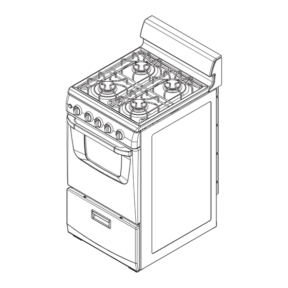
20" (50.8 CM) FREESTANDING GAS RANGE
INSTRUCCIONES DE INSTALACIÓN
ESTUFA AUTÓNOMA A GAS DE 20" (50,8 CM)
To the installer: Please leave this instruction book with the unit.
To the consumer: Please read and keep this book for future
reference.
W10173755C
INSTALLATION INSTRUCTIONS
with standard clean oven
con horno de limpieza estándar
Table of Contents/Índice..........................................2
Para el instalador: favor de dejar este manual de instrucciones
con la unidad.
Para el consumidor: favor de leer y guardar este manual para
futura referencia.
Advertisement
Table of Contents

Related Manuals for Amana FREESTANDING GAS RANGE


Summary of Contents for Amana FREESTANDING GAS RANGE
-
Page 1: Installation Instructions
INSTALLATION INSTRUCTIONS 20" (50.8 CM) FREESTANDING GAS RANGE with standard clean oven INSTRUCCIONES DE INSTALACIÓN ESTUFA AUTÓNOMA A GAS DE 20" (50,8 CM) con horno de limpieza estándar Table of Contents/Índice..........2 Para el instalador: favor de dejar este manual de instrucciones To the installer: Please leave this instruction book with the unit. -
Page 2: Table Of Contents
TABLE OF CONTENTS ÍNDICE RANGE SAFETY ................2 SEGURIDAD DE LA ESTUFA ............ 17 INSTALLATION REQUIREMENTS ..........4 REQUISITOS DE INSTALACIÓN..........19 Tools and Parts ................4 Herramientas y piezas ............19 Location Requirements.............. 4 Requisitos de ubicación ............19 Electrical Requirements ............6 Requisitos eléctricos.............. - Page 3 WARNING: Gas leaks cannot always be detected by smell. Gas suppliers recommend that you use a gas detector approved by UL or CSA. For more information, contact your gas supplier. If a gas leak is detected, follow the “What to do if you smell gas” instructions.
-
Page 4: Installation Requirements
INSTALLATION REQUIREMENTS Tools and Parts Location Requirements Gather the required tools and parts before starting installation. IMPORTANT: Observe all governing codes and ordinances. Do Read and follow the instructions provided with any tools listed not obstruct flow of combustion and ventilation air. here. - Page 5 Product Dimensions Installation Clearances Cabinet opening dimensions shown are for 25" (64 cm) countertop depth, 24" (61 cm) base cabinet depth and 36" (91.4 cm) countertop height. If the cabinet depth is greater than 24" (61 cm), the oven frame must extend beyond cabinet fronts by ⁄...
-
Page 6: Electrical Requirements
Electrical Requirements Gas Supply Requirements WARNING Electrical Shock Hazard Plug into a grounded 3 prong outlet. Do not remove ground prong. Do not use an adapter. Do not use an extension cord. Failure to follow these instructions can result in death, fire, or electrical shock. - Page 7 Flexible metal appliance connector: Gas Pressure Regulator ■ If local codes permit, a new CSA design-certified, 4-5 ft (122-152.4 cm) long, ⁄ " (1.3 cm) or ⁄ " (1.9 cm) I.D., The gas pressure regulator supplied with this range must be flexible metal appliance connector may be used for used.
-
Page 8: Installation Instructions
INSTALLATION INSTRUCTIONS Before moving range, slide range onto shipping base, cardboard Unpack Range or hardboard. 1. Remove template from the anti-tip bracket kit found inside the oven cavity. 2. Place template on the floor in cabinet opening so that the left edge is against cabinet and top edge is against rear wall, molding or cabinet. -
Page 9: Verify Anti-Tip Bracket Location
9. Open the broiler door. Use a ⁄ " drive ratchet to lower the rear 3. If range is not level, pull range forward until rear leveling leg is leveling legs one-half turn. Use slip-joint pliers to lower the removed from the anti-tip bracket. Use ⁄... -
Page 10: Check Operation
Typical flexible connection 5. Close the broiler door. 1. Use a combination wrench to attach the flexible connector to 6. Place burners, burner caps and grates on the cooktop. the adapters. Check that connector is not kinked. WARNING Electrical Shock Hazard Plug into a grounded 3 prong outlet. -
Page 11: Complete Installation
If the low flame needs adjusting: 2. Open oven door and remove oven racks, oven tray, flame spreader and set aside. 1. Turn control knob to the “LO” setting and remove control knob. 2. Insert a small flat-blade screwdriver into the valve stem. Turn the valve adjusting screw to obtain the smallest flame that will not go out when the control of a cold burner is quickly turned from “HI”... -
Page 12: Gas Conversions
GAS CONVERSIONS 2. Unplug or disconnect power. 3. Open broiler door and remove broiler pan. The gas pressure regulator is located in the back right hand corner of the broiler compartment. A. Gas pressure regulator A. Gas pressure regulator IMPORTANT: Do not remove the gas pressure regulator. NOTE: Do not remove the spring beneath the cap. -
Page 13: Complete Conversion
2. Locate LP gas orifice spuds for top burners in the bag To Convert Oven Burner containing literature included with the range. Two LP gas spuds are stamped “88” and two “78.” 1. Open oven door and remove oven racks, oven tray, flame 3. -
Page 14: Natural Gas Conversion
3. Open broiler door and remove broiler pan. The gas pressure Natural Gas Conversion regulator is located in the back right hand corner of the broiler compartment. A. Gas pressure regulator IMPORTANT: Do not remove the gas pressure regulator. NOTE: Do not remove the spring beneath the cap. 4. -
Page 15: Complete Conversion
3. Remove the LP gas orifice spuds using a 7 mm combination To Convert Oven Burner wrench. 4. Install Natural gas orifice spuds using a 7 mm combination wrench. 1. Open oven door and remove oven racks, oven tray, flame spreader and set aside. - Page 16 Notes...
-
Page 17: Seguridad De La Estufa
SEGURIDAD DE LA ESTUFA... - Page 18 heridas o la muerte. – aparato electrodoméstico. – PASOS QUE USTED DEBE SEGUIR SI HUELE A GAS: • No trate de encender ningún aparato electrodoméstico. • No toque ningún interruptor eléctrico; no use ningún teléfono en su edificio. • Siga las instrucciones de su proveedor de gas. •...
-
Page 19: Requisitos De Instalación
REQUISITOS DE INSTALACIÓN Herramientas y piezas Requisitos de ubicación IMPORTANTE: Observe todos los códigos y reglamentos Reúna las herramientas y piezas necesarias antes de comenzar la instalación. Lea y siga las instrucciones provistas con aplicables. No obstruya el flujo de aire para la combustión y la cualquiera de las herramientas enlistadas aquí. - Page 20 Requisitos de instalación adicionales para las casas Espacios libres para la instalación rodantes La instalación de esta estufa debe ajustarse al Estándar de Las dimensiones de la abertura del armario que se muestra son seguridad y construcción de casas fabricadas, Título 24 CFR, para una profundidad de mostrador de 25"...
-
Page 21: Requisitos Eléctricos
Requisitos eléctricos Requisitos del suministro de gas ADVERTENCIA ADVERTENCIA Peligro de Explosión Peligro de Choque Eléctrico Use una línea de suministro de gas nueva con Conecte a un contacto de pared de conexión a tierra de aprobación de CSA International. 3 terminales. - Page 22 Línea de suministro de gas Regulador de la presión de gas ■ Provea una línea de suministro de gas de tubería rígida de ⁄ " Deberá usarse el regulador de la presión de gas suministrado con hacia la ubicación de la estufa. Una tubería de tamaño más esta estufa.
-
Page 23: Instrucciones De Instalación
INSTRUCCIONES DE INSTALACIÓN Instalación del soporte anti-vuelco Desempaque la estufa ADVERTENCIA Peligro de Vuelco 1. No use la agarradera de la puerta del horno para levantar o mover la estufa. Un niño o un adulto puede volcar accidentalmente la estufa y resultar muerto. 2. -
Page 24: Verificación De La Ubicación Del Soporte Anti-Vuelco
5. Para montar el soporte anti-vuelco al piso de madera, perfore 12. Si instala la estufa en una casa rodante, deberá fijar la dos orificios de ⁄ " (0,32 cm) en las posiciones marcadas en la estufa al piso. El método que se use para fijar esta estufa plantilla del soporte. -
Page 25: Conexión Del Suministro De Gas
Conexión flexible típica Conexión del suministro de gas 1. Use una llave de combinación para ajustar el conector flexible a los adaptadores. Cerciórese de que el conector no esté torcido. ADVERTENCIA Peligro de Explosión Use una línea de suministro de gas nueva con aprobación de CSA International. -
Page 26: Verifique El Funcionamiento
3. Abra la válvula de cierre manual de la línea de suministro de Verifique el funcionamiento de los quemadores de la gas. La válvula está “abierta” cuando la manija está paralela al tubo de gas. superficie de cocción 1. Si se quitaron antes el control de panel y las perillas, vuelva a colocar las perillas. -
Page 27: Complete La Instalación
5. Vuelva a encender el horno y fíjese que la llama sea la Verifique el funcionamiento del quemador de adecuada. Si la llama todavía no está ajustada debidamente, apague el horno, espere que se enfríe el quemador del mismo asar/del horno y repita el paso 4 hasta ajustar la llama como es debido. -
Page 28: Conversiones De Gas
CONVERSIONES DE GAS ADVERTENCIA Cómo convertir el regulador de la presión del gas 1. Asegúrese de que la válvula de cierre manual esté en la posición cerrada. Peligro de Explosión Use una línea de suministro de gas nueva con aprobación de CSA International. A. -
Page 29: Complete La Conversión
5. Coloque las espitas de los orificios de gas natural en la bolsa Cómo convertir los quemadores de superficie de piezas para usarlas en el futuro y guárdela en la bolsa con material impreso. 1. Saque la parrilla, las tapas del quemador y los quemadores. 6. -
Page 30: Conversión De Gas Natural
4. Cierre la puerta del asador y gire la perilla a “Apagado” (OFF). 5. Consulte la sección “Complete la instalación” para terminar este procedimiento. Conversión de gas natural A. Válvula de cierre en posición “cerrada” ADVERTENCIA B. Línea de suministro de gas C. - Page 31 Cómo convertir los quemadores de superficie 1. Saque las parrillas, las tapas del quemador y los quemadores. Quemador Quemador estándar 125 potente 149 Quemador Quemador potente 149 estándar 125 A. Tapa del quemador B. Quemador 2. Ubique las espitas de los orificios de gas natural para los quemadores superiores, que están en la bolsa con material impreso incluida con la estufa.
-
Page 32: Complete La Conversión
6. Coloque la espita del quemador del horno de gas LP en la 3. Vea la sección “Verifique el funcionamiento” para los bolsa de piezas junto con las espitas del quemador de la ajustes apropiados de encendido, funcionamiento y llama superficie de cocción de gas LP para usarlas en el futuro y del quemador.
Need help?
Do you have a question about the FREESTANDING GAS RANGE and is the answer not in the manual?
Questions and answers
how to adjust the air for propane on the oven burner