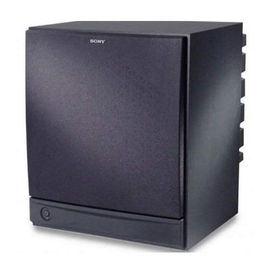
Sony SA-WM40 Service Manual
Hide thumbs
Also See for SA-WM40:
- Operating instructions manual (24 pages) ,
- Service manual (13 pages) ,
- Specifications (1 page)
Subscribe to Our Youtube Channel
Summary of Contents for Sony SA-WM40
- Page 1 SA-WM40 SERVICE MANUAL US Model Canadian Model AEP Model UK Model E Model Australian Model SPECIFICATIONS ACTIVE SUBWOOFER...
-
Page 2: Safety Check-Out
DE FONCTIONNEMENT. NE REMPLACER CES COM- OPERATION. REPLACE THESE COMPONENTS WITH SONY PARTS WHOSE PART NUMBERS APPEAR AS POSANTS QUE PAR DES PIÈCES SONY DONT LES NUMÉROS SONT DONNÉS DANS CE MANUEL OU SHOWN IN THIS MANUAL OR IN SUPPLEMENTS PUB- DANS LES SUPPLÉMENTS PUBLIÉS PAR SONY. - Page 3 SECTION 2 SECTION 1 DIAGRAMS GENERAL • Location of controls 2-1. NOTE FOR PRINTED WIRING BOARD AND SCHEMATIC DIAGRAM Note on Printed Wiring Boards: Note on Schematic Diagram: – Front View (a part) – • X : parts extracted from the component side. •...
-
Page 4: Printed Wiring Boards
SA-WM40 2-2. PRINTED WIRING BOARDS • See page 3 for Note on Printed Wiring Boards. • See page 3 for Circuit Boards Location. • Semiconductor Location Ref. No. Location D501 CONTROL BOARD D502 POWER SW UC D503 VR501 SW501 VR502... -
Page 5: Schematic Diagram
SA-WM40 2-3. SCHEMATIC DIAGRAM • See page 3 for Note on Schematic Diagram. The components identified by mark 0 or dotted Les composants identifiés par une marque 0 sont line with mark 0 are critical for safety. critiques pour la sécurité. Ne les remplacer que Replace only with part number specified. -
Page 6: Section 3 Exploded View
SECTION 3 SECTION 4 CONTROL MAIN EXPLODED VIEW ELECTRICAL PARTS LIST NOTE: NOTE: • -XX and -X mean standardized parts, so they • Items marked “*” are not stocked since they • Abbreviation • Due to standardization, replacements in the •... - Page 7 MAIN Ref. No. Part No. Description Remark Ref. No. Part No. Description Remark C619 1-130-485-00 MYLAR 0.015uF Q603 8-729-119-54 TRANSISTOR 2SA1464-T2Y13 C620 1-101-001-00 CERAMIC 0.001uF Q604 8-729-119-78 TRANSISTOR 2SC2785-F C621 1-130-491-00 MYLAR 0.047uF Q605 8-729-119-78 TRANSISTOR 2SC2785-F C623 1-130-483-00 MYLAR 0.01uF Q606 8-729-214-51 TRANSISTOR...
- Page 8 MAIN POWER SW UC POWER TR Ref. No. Part No. Description Remark Ref. No. Part No. Description Remark < SWITCH > 0 R625 1-247-688-11 CARBON 1/4W F 0 R640 1-216-364-11 METAL OXIDE FILM 0.39 S801 1-554-920-11 SWITCH, PUSH (AC POWER) (1 KEY) 0 R641 1-216-364-11 METAL OXIDE FILM 0.39 (POWER)
-
Page 9: Accessories And Packing Materials
POWER TR Ref. No. Part No. Description Remark Ref. No. Part No. Description Remark 0 R621 1-216-364-11 METAL OXIDE FILM 0.39 0 R622 1-216-364-11 METAL OXIDE FILM 0.39 0 R623 1-216-364-11 METAL OXIDE FILM 0.39 0 R624 1-216-364-11 METAL OXIDE FILM 0.39 ************************************************************** MISCELLANEOUS **************... - Page 10 SA-WM40 Sony Corporation 9-929-065-11 2000B0585-1 Home Audio Division Company Printed in Japan C 2000. 2 Published by Quality Assurance Dept.


Need help?
Do you have a question about the SA-WM40 and is the answer not in the manual?
Questions and answers