Table of Contents
Advertisement
Quick Links
Advertisement
Table of Contents

Related Manuals for NAD C420


Summary of Contents for NAD C420
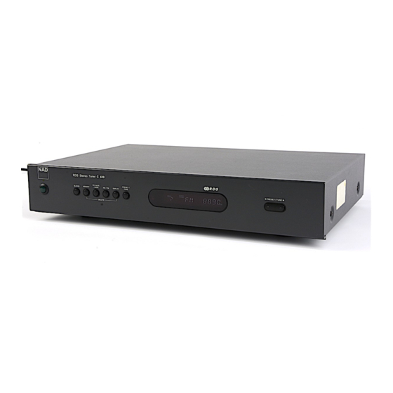
- Page 1 C 420 S T E R E O AM/FM TUNER...
-
Page 2: Table Of Contents
SERVICE SAFETY PRECAUTIONS Safety check out (Only U.S.A. model) Before returning the product to the customer, make leakage current or resistance measurements to determine that exposed parts are acceptably insulated from the supply circuit. Parts marked with the symbol are critical with regard to the risk of fire and electric shock. Replace only with parts recommended by the manufacturer. -
Page 3: Specifications
SPECIFICATIONS AM TUNER SECTION Input level is expressed as the reading in open-circuit of 75-ohm source impedance signal generator ≤30dBµ Usable Sensitivity (999/1000kHz) ≥38dB S/N Ratio (5mV in) ≤3% THD (5mV in) ≥36dB IF Rejection (450kHz) ≥28dB Image Rejection (F+2xIF) ≥17dB Selectivity Output... -
Page 4: Rear Panel / Front Panel
REAR PANEL / FRONT PANEL REAR PANEL 1. FM ANTENNA 4. NAD-LINK IN/OUT 2. AM ANTENNA 5. 12V TRIGGER IN 3. OUTPUT 6. AC LINE CORD FRONT PANEL 1. POWER ON / OFF 6. AM / FM 2. STAND-BY LED 7. -
Page 5: Disassembly Instructions
DISASSEMBLY INSTRUCTIONS 1. Remove machine screws M 4.0 x 6.0 ( 1 to 4 ) from the side panels. Remove tapping screw 3.0 x 8.5 5 from the back panel. Refer to Figure No.1. Figure No.1 2. Pull both sides of the TOP COVER slightly outwards 6 and tilt approx. 35˚ and then remove in the direction as indicated by the arrow 7 . -
Page 6: Block Diagram
BLOCK DIAGRAM... -
Page 7: Wiring Diagram
WIRING DIAGRAM KEY BOARD POWER SUPPLY BOARD TRANSFORMER LED BOARD WHITE BLUE YELLOW MAIN BOARD Trigger In Audio L,R Out... -
Page 8: Adjustment Points Diagram
ADJUSTMENT POINTS DIAGRAM... -
Page 9: Instrument Setup
INSTRUMENT SETUP 1. FM MEASUREMENT Fig. 1 ANTENNA OUTPUT TERMINAL TERMINAL DISTORTION UNIT SIGNAL METER GENERATOR OUTPUT TERMINAL P901 VOLTMETER MILLIVOLT- METER OSCILLOSCOPE ANTENNA OUTPUT Fig. 2 TERMINAL TERMINAL DISTORTION UNIT STEREO SIGNAL METER GENERATOR GENERATOR OSCILLOSCOPE VOLTMETER 2. RDS MEASUREMENT ANTENNA TERMINAL Fig. -
Page 10: Alignment Procedures
ALIGNMENT PROCEDURES FM/RDS SECTION - FM mono: 1kHz, 75kHz devi., 60dB/µV - FM stereo: 1kHz, 67.5kHz devi., 60dB/µV Pilot signal 19kHz 7.5kHz devi. OUTPUTS - Connect the 47Kohm resistor unless otherwise noted. Connection FM SG Stereo mod- Tuning Output Adjustment Adjust Item Step... -
Page 11: Pcb Layout
PCB LAYOUT POWER SUPPLY BOARD KEY BOARD LED BOARD... - Page 12 MAIN BOARD...
-
Page 13: Schematic Diagram
SCHEMATIC DIAGRAM KEYBOARD / CPU HNA - 10SM12 M302 M988 GREEN NOTE: 1. RESISTORS ARE CARBON FILM 5% 1/8W UNLESS OTHERWISE SPECIFIED. 2. CERAMIC CAPACITORS ARE 50V 10% UNLESS OTHERWISE SPECIFIED. - Page 14 TUNER M987 LEFT OUT RIGHT OUT NOTE: 1. RESISTORS ARE CARBON FILM 5% 1/8W UNLESS OTHERWISE SPECIFIED. 2. CERAMIC CAPACITORS ARE 50V 10% UNLESS OTHERWISE SPECIFIED.
-
Page 15: Ic Block Diagram
IC BLOCK DIAGRAM U201: LC866448B S15/T15 S14/T14 S13/T13 S12/T12 S11/T11 S10/T10 S9/T9 S8/T8 VSS2 S7/T7 P10/SO0 S6/T6 P11/SI0/SB0 S5/T5 P12/SCK0 S4/T4 P13/SO1 S3/T4 P14/SI1/SB1 S2/T2 P15/SCK1 S1/T1 P16/BUZ S0/T1 U202: 24C08 START STOP LOGIC SERIAL CONTROL H.V. PUMP/TIMING LOGIC LOAD COMP DATA RECOVERY DEVICE... - Page 16 U303: 74HCT00 U402: NJM78M56FA OUTPUT INPUT U901: LA1837 3 rd 5 th DECODER ANTI-BIRIDE RF.AMP BUFF MUTE P-DET STEREO ¯ AM IF PILOT 304kHz COMP S-METER AM/FM S-METER S-CURVE IF-BUFF TUNING STEREO DRIVE DRIVE AM IF...
- Page 17 U902: LC72723M V REF FLOUT Vddd Vdda CLOCK RECOVERY REFERENCE (57kHz) (1187.5Hz) VOLTAGE Vssd Vssa V REF 57kHz RDDA DATA MPXIN ANTIALIASING SMOOTHING (SCF) DECODER FILTER FILTER RDCL MODE (128bits) CLK(4.332MHz) RDS-ID/READY TEST RDS-ID TEST DETECT X IN X OUT U903: LC7218 REFERENCE PHASE DETECTOR...
-
Page 18: Electrical Parts List
ELECTRICAL PARTS LIST Reference No. Part No. Description KEYBOARD ASSEMBLY PC BOARD 3000 PCB-N0930C-KEY KEY PCB ASSY C420 0303 2460-1960-0 VFD SAMSUNG HNA-105M12 CAPACITORS C201 157B-107M-5-KMK CE 6.3V 100µF 20% RL 6x7 ELNA C202 153F-103J-5-KM CM 50V 0.01µF 5% RL 6.0x7.0... - Page 19 CE 25V 1000µF 20% RL 10x20 ELNA C414-C418 157F-107M-5-KUK CE 50V 100µF 20% RL 6.3x11 ELNA C419 157C-476M-5-IMK CE 10V 47µF 20% RL 5x7 ELNA C420 150F-104K-5-II CC 50V 0.1µF 10% RL 5x5 C421 157E-107M-5-KUK CE 25V 100µF 20% RL 6.3x11 ELNA C901 *C 150F-223K-2-FD CC 50V 0.022µF 10% AT 3.2x2.2...
- Page 20 Reference No. Part No. Description C931 157B-107M-5-KM CE 6.3V 100µF 20% RL 6x7 C932, C941 150F-223K-2-FD CC 50V 0.022µF 10% AT 3.2x2.2 C942 157D-107M-5-KUK CE 16V 100µF 20% RL 6.3x11 ELNA C943 157F-225M-5-GM CE 50V 2.2µF 20% RL 4x7 C944 157F-475M-5-GM CE 50V 4.7µF 20% RL 4x7 C945...
- Page 21 Reference No. Part No. Description J202B 2101-1591-0 FLEXIBLE CONN. 35P P1.25 TOP ENTRY J203B 2102-051S-004 5P ST.WAFER P=2.5 COULOMB J401B 2102-081S-004 WAFER 8P P2.5 ST. P901 2113-1160-0 WAFER 2P ST. P=2.5 NH (JST) COILS L201, L901 1801-220K-M COIL 22µH 10% AL BL7 L903, L904 5600-3386-S COIL MPx LPF NMC-4085...
- Page 22 Reference No. Part No. Description R903 *C 4701-123J-C RCF 1/8W 12K 5% ATS R904 *C 4701-331J-C RCF 1/8W 330R 5% ATS R905 *C 4701-681J-C RCF 1/8W 680R 5% ATS R906 4701-103J-C RCF 1/8W 10K 5% ATS R907 *C 4701-332J-C RCF 1/8W 3.3K 5% ATS R908 *C 4701-471J-C RCF 1/8W 470R 5% ATS...
- Page 23 Reference No. Part No. Description U201 3131-9750-1 IC LC866448B 8 BIT SINGLE CHIP MCU MASKED U202 3131-7250-0 IC 24C08 8K EEPROM U303 3130-7370-0 IC 74HCT00 NAND GATE U402 3130-8190-0 IC NJM78M56FA 5.6V REGULATOR U901 3130-8180-0 IC LA1837 AM/FM IF U902 3131-9040-0 IC LC72723M RDS DEMODULATOR MFP16 U903...
-
Page 24: Exploded View
EXPLODED VIEW... -
Page 25: Exploded View Parts List
EXPLODED VIEW PARTS LIST ITEM Part No. Description 0100 *AH 1402-3515-1 CHASSIS C420 AH W/SS-PAINT 0100 *C 1402-3514-1 CHASSIS C420 C W/SS-PAINT 0101 1402-3530-0 COVER 0102 1403-7120-1 FASCIA 0105 1806-3541-0 X'FORMER 120/230V I/P 0106 2442-1000-0 POWER BUTTON 0107 2444-1201-0 BUTTON TRIO... -
Page 26: Packing Diagram
RCA CABLE 2107-0661-1 300-OHM T ANTENNA 2113-1155-0 AM LOOP ANTENNA 2103-6101-0 RF CONNECTION PLUG Proprietary information for servicing purposes only. The information herein may not be used com- mercially without the prior written agreement of NAD Electronics International, Toronto, Canada. - Page 27 © NAD 2001 NAD ELECTRONICS INTERNATIONAL TORONTO...
Need help?
Do you have a question about the C420 and is the answer not in the manual?
Questions and answers