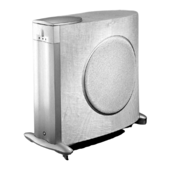
Infinity Prelude MTS Service Manual
Infinity prelude mts subwoofer service manual
Hide thumbs
Also See for Prelude MTS:
- Owner's manual (32 pages) ,
- User manual (24 pages) ,
- Quick start manual (4 pages)
Summary of Contents for Infinity Prelude MTS
- Page 1 PRELUDE MTS SUBWOOFER SERVICE MANUAL Infinity Systems, Inc 250 Crossways Park Dr. REV 6 6/2007 Woodbury, New York 11797...
-
Page 2: Table Of Contents
Prelude MTS CONTENTS SPECIFICATIONS …….……………….…………….………………….3 DETAILED SPECIFICATIONS ……………………..…………………4 CONTROLS & CONNECTIONS ………………………………………6 OPERATION/AMPLIFIER REMOVAL……… ..……..…..…….…….10 MECHANICAL/PACKING PARTS LIST………………..….…………11 EXPLODED VIEW ………………………………………..……………13 PACKAGING ……………………………..…………….…………….…14 PRELUDE MTS ADJUST BIAS PROCEDURE…….…..……….………15 ELECTRICAL PARTS LIST (120v)……………….….…..….…………16 INTEGRATED CIRCUIT DIAGRAMS …………….….………………24 PRINTED CIRCUIT BOARD DIAGRAMS….……….……..…………25 SCHEMATICS……………….…..……….……….….…………………29... -
Page 3: Specifications
Prelude MTS Subwoofer Prelude MTS Subwoofer Specifications... -
Page 4: Detailed Specifications
Prelude MTS Subwoofer Detailed Specifications... - Page 5 Prelude MTS Subwoofer Detailed Specifications (Cont.)
-
Page 6: Controls & Connections
Prelude MTS Subwoofer... - Page 7 Prelude MTS Subwoofer...
- Page 8 Prelude MTS Subwoofer...
- Page 9 Prelude MTS Subwoofer...
-
Page 10: Operation/Amplifier Removal
Prelude MTS Subwoofer Operation Amplifier Removal... -
Page 11: Mechanical/Packing Parts List
Prelude MTS Subwoofer Mechanical & Packaging Parts List Cabinet Prelude MTS Subwoofer (Not for Sale) Low Frequency Transducer 12” Cast frame C.M.M.D., Shielded 335036-001 DC Resistance 7.6 ohms ±10% (Woofer) Complete Subwoofer Amp assembly Not For Sale Woofer Grille retainers... -
Page 12: Pph #10-32 X .75 Blk
Prelude MTS Subwoofer Mechanical & Packaging Parts List (Cont’d) Connector Plate 335249-001 Connector Plate Gasket 335355-002 PPH #10-32 x 1 BLK Screw (4) 900401-016 PPH #10-32 x .75 BLK Screw (4) 900401-012 PB FPH #10 x .625 BLK Screw (8) 908401-010 PB FPH #10 x .75 BLK... -
Page 14: Packaging
Prelude MTS Subwoofer Packaging... -
Page 15: Prelude Mts Adjust Bias Procedure
PRELUDE MTS ADJUST BIAS PROCEDURE (Mandatory when any output MOSFET transistors Q305,310,320,321,306,307,311,312 are replaced) 1. Amplifier should be unplugged and OFF. 2. Remove Amp assembly from cabinet, following the instructions on Page 10. 3. Identify the Linear board assembly (PCB with the output transistors) 4. -
Page 16: Electrical Parts List (120V)
Prelude MTS Subwoofer Prelude Amp Assembly Parts List Part# Description Designator... - Page 17 Prelude MTS Subwoofer Prelude Amp Assembly Parts List (Cont.) Part# Description Designator...
- Page 18 Prelude MTS Subwoofer Prelude Amp Assembly Parts List (Cont.) Part# Description Designator...
- Page 19 Prelude MTS Subwoofer Prelude Amp Assembly Parts List (Cont.) Part# Description Designator...
- Page 21 Prelude MTS Subwoofer Prelude Amp Assembly Parts List (Cont.) Part# Description Designator...
- Page 22 Prelude MTS Subwoofer Prelude Amp Assembly Parts List (Cont.) 630049 PCB, INPUT Part# Description Designator...
- Page 23 Prelude MTS Subwoofer Prelude Amp Assembly Parts List (Cont.) Part# Description Designator...
-
Page 24: Integrated Circuit Diagrams
Prelude MTS Subwoofer Integrated Circuit Diagrams OPAMP, DUAL 8PIN DIL TL082 OPAMP, QUAD 14P DIL TL074/084, LM324N U101 COMPARATOR U102, U103, U201, U202, U203, U301, U306 A OUTPUT A -INPUT B OUTPUT OUTPUT A OUTPUT D A +INPUT B -INPUT... -
Page 25: Printed Circuit Board Diagrams
Prelude MTS Subwoofer EMI PCB (AC Filter) Input PCB... - Page 26 Prelude MTS Subwoofer Linear/Buck PCB...
- Page 27 Prelude MTS Subwoofer Feature PCB...
- Page 28 Prelude MTS Subwoofer Power Supply PCB...


Need help?
Do you have a question about the Prelude MTS and is the answer not in the manual?
Questions and answers