Table of Contents
Advertisement
Service
Manual
MULTI-CD/DAB CONTROL HIGH POWER CD PLAYER WITH RDS TUNER
DEH-P7300R
DEH-P6300R
- This service manual should be used together with the following manual(s):
Model No.
Order No.
CX-977
CRT2624
CONTENTS
1. SAFETY INFORMATION ............................................2
2. EXPLODED VIEWS AND PARTS LIST .......................3
4. PCB CONNECTION DIAGRAM ................................28
5. ELECTRICAL PARTS LIST ........................................36
6. ADJUSTMENT..........................................................45
PIONEER CORPORATION
PIONEER ELECTRONICS SERVICE INC.
PIONEER EUROPE NV
Haven 1087 Keetberglaan 1, 9120 Melsele, Belgium
PIONEER ELECTRONICS ASIACENTRE PTE.LTD. 253 Alexandra Road, #04-01, Singapore 159936
C PIONEER CORPORATION 2001
DEH-P7300R/X1N/EW
EQ
SOURCE
DISP
Mech. Module Remarks
S9
CD Mech. Module:Circuit Description, Mech.Description, Disassembly
4-1, Meguro 1-Chome, Meguro-ku, Tokyo 153-8654, Japan
P.O.Box 1760, Long Beach, CA 90801-1760 U.S.A.
SELECT
SFEQ
1
2
3
4
5
6
E
B
FUNC
AUDIO
X1N/EW
7. GENERAL INFORMATION .......................................50
7.1 DIAGNOSIS ........................................................50
7.1.1 TEST MODE ..............................................50
7.1.2 DISASSEMBLY .........................................54
7.2 IC ........................................................................61
7.3 OPERATIONAL FLOW CHART ...........................71
8. OPERATIONS AND SPECIFICATIONS.....................72
ORDER NO.
CRT2649
X1N/EW
K-ZZD. FEB. 2001 Printed in Japan
Advertisement
Table of Contents

Related Manuals for Pioneer DEH-P7300R/X1N/EW


Summary of Contents for Pioneer DEH-P7300R/X1N/EW
-
Page 1: Table Of Contents
PIONEER ELECTRONICS SERVICE INC. P.O.Box 1760, Long Beach, CA 90801-1760 U.S.A. PIONEER EUROPE NV Haven 1087 Keetberglaan 1, 9120 Melsele, Belgium PIONEER ELECTRONICS ASIACENTRE PTE.LTD. 253 Alexandra Road, #04-01, Singapore 159936 C PIONEER CORPORATION 2001 K-ZZD. FEB. 2001 Printed in Japan... -
Page 2: Safety Information
DEH-P7300R,P6300R - CD Player Service Precautions 2. During disassembly, be sure to turn the power off 1. For pickup unit(CXX1480) handling, please refer since an internal IC might be destroyed when a con- to"Disassembly"(see page 54). nector is plugged or unplugged. During replacement, handling precautions shall be 3. -
Page 3: Exploded Views And Parts List
DEH-P7300R,P6300R 2. EXPLODED VIEWS AND PARTS LIST 2.1 PACKING(DEH-P7300R/X1N/EW) 23 23 NOTE: - Parts marked by “*” are generally unavailable because they are not in our Master Spare Parts List. - Screws adjacent to mark on the product are used for disassembly. - Page 4 DEH-P7300R,P6300R - Owner's Manual, Installation Manual Model Part No. Language DEH-P7300R/X1N/EW CRD3378 English, Spanish CRD3379 German, French CRD3380 Italian, Dutch CRD3381 English, Spanish, German, French, Italian, Dutch 2.2 PACKING(DEH-P6300R/X1N/EW)
- Page 5 DEH-P7300R,P6300R - PACKING SECTION PARTS LIST Mark No. Description Part No. Mark No. Description Part No. 1 Carton CHG4324 9-3 Owner’s Manual CRD3379 2 Cord Assy CDE6435 9-4 Owner’s Manual CRD3380 3 Accessory Assy CEA2397 9-5 Installation Manual CRD3381 4 Screw CBA1002 9-6 Passport CRY1013...
- Page 6 DEH-P7300R,P6300R 2.3 EXTERIOR(DEH-P7300R/X1N/EW)
- Page 7 DEH-P7300R,P6300R - EXTERIOR SECTION PARTS LIST Mark No. Description Part No. Mark No. Description Part No. 1 Screw BMZ30P040FZK 51 Arm CNV6508 2 Screw BMZ30P100FMC 52 Panel Unit CWM7375 3 Screw BSZ26P060FMC 53 Socket(CN1950) CKS3550 4 Screw BSZ30P040FMC 54 Connector(CN1951) CKS4206 5 Cord Assy CDE6435...
- Page 8 DEH-P7300R,P6300R 2.4 EXTERIOR(DEH-P6300R/X1N/EW)
- Page 9 DEH-P7300R,P6300R - EXTERIOR SECTION PARTS LIST Mark No. Description Part No. Mark No. Description Part No. 1 Screw BMZ30P040FZK 51 Arm CNV6508 2 Screw BMZ30P100FMC 52 Panel Unit CWM7375 3 Screw BSZ26P060FMC 53 Socket(CN1950) CKS3550 4 Screw BSZ30P040FMC 54 Connector(CN1951) CKS4206 5 Cord Assy CDE6435...
- Page 10 DEH-P7300R,P6300R 2.5 CD MECHANISM MODULE...
- Page 11 DEH-P7300R,P6300R - CD MECHANISM MODULE SECTION PARTS LIST Mark No. Description Part No. Mark No. Description Part No. 1 Control Unit CWX2481 46 Gear CNV6320 2 Connector(CN701) CKS1959 47 Arm CNV6322 3 Connector(CN101) CKS3486 48 Arm CNV6323 4 Screw BMZ20P025FMC 49 Arm CNV6324 5 Screw...
-
Page 12: Block Diagram And Schematic Diagram
DEH-P7300R,P6300R 3. BLOCK DIAGRAM AND SCHEMATIC DIAGRAM 3.1 BLOCK DIAGRAM(DEH-P7300R/X1N/EW) TUNER AMP UNIT FM/AM TUNER UNIT Q153 Q151 Q155 FM/AM 1ST IF 10.7MHz MPXREF 41kHz CN401 AMRF T51 Q51 CF51 CF52 CF53 AMDET AMANT L ch IC 2 FM MPX... -
Page 13: Panel Unit
DEH-P7300R,P6300R HIGH OUT RESET CN351 IC 961 OUT1 PRE OUT L S-80735ANDZI Q351 IC 271 PA2028A CN352-1 OUT3 TMUTE Q352 OUT5 fm/AM SYSTEM -COM Q353 IC 601(1/2) PD5614A CN352-2 ldet Q911 NL2DT Q931 bsens SDBW TUNPCE asens TUNPCK tunpce@ TUNPDO ASENBO CN901 30 29 81... - Page 14 DEH-P7300R,P6300R 3.2 BLOCK DIAGRAM(DEH-P6300R/X1N/EW) TUNER AMP UNIT FM/AM TUNER UNIT Q153 Q151 Q155 FM/AM 1ST IF 10.7MHz MPXREF 41kHz CN401 AMRF T51 Q51 CF51 CF52 CF53 AMDET AMANT L ch IC 2 FM MPX Q501 R ch DECODER ANT1 ADJ COMP MIXER, IF AMP, DET.
- Page 15 DEH-P7300R,P6300R RESET CN351 IC 961 PRE OUT L S-80735ANDZI Q351 TMUTE fm/AM SYSTEM -COM Q353 IC 601(1/2) PD5614A CN352-2 ldet Q911 NL2DT Q931 bsens SDBW TUNPCE asens TUNPCK tunpce@ TUNPDO ASENBO CN901 30 29 81 ELECTRONIC VOLUME/ POWER AMP SOURCE SELECTOR TUN L IN3-L FL—...
- Page 16 DEH-P7300R,P6300R 3.3 OVERALL CONNECTION DIAGRAM(GUIDE PAGE) Note: When ordering service parts, be sure to refer to “EXPLODED VIEWS AND PARTS LIST” or “ELECTRICAL PARTS LIST”. CONTROL UNIT CN701 Large size SCH diagram CD:+3.8dBs Guide page IP-BUS DRIVER Detailed page P7300R >...
-
Page 17: Tuner Amp Unit
DEH-P7300R,P6300R P7300R P6300R R860 C854 TUNER AMP UNIT P7300R:10/35 P6300R:10/16 P7300R:10/35 P6300R:10/16 P7300R P6300R P7300R P7300R 6300R %): -16.5dBs P7300R:10/35 %): -27.0dBs P7300R P6300R:10/16 S: +2.2dBs FM(100%):+12.1dBs D: +3.8dBs AM(30%): +3.6dBs IP-BUS:+14.8dBs P7300R:10/35 CD:+15.4dBs P6300R:10/16 P6300R FM(100%):+5.84dBs AM(30%): -2.66dBs IP-BUS:+8.54dBs CD:+9.14dBs P7300R FM(100%):+4.6dBs... - Page 18 DEH-P7300R,P6300R IP-BUS:+2.2dBs %):-26.0dBs %):-15.5dBs TEL/MIC...
- Page 19 DEH-P7300R,P6300R SENSE DETACH CN1901 UNIT KEYBOARD AM(30%):-26.0dBs UNIT TUNER FM/AM FM(100%):-15.5dBs A-a B...
- Page 20 DEH-P7300R,P6300R...
- Page 21 DEH-P7300R,P6300R...
- Page 22 DEH-P7300R,P6300R 3.4 KEYBOARD UNIT REMOTE CONTROL SENSOR VOLUME S1930 CSD1059 TEXT SFEQ CSG1113,CSG1147 CSG1147...
- Page 23 DEH-P7300R,P6300R KEYBOARD UNIT GRILLE -COM OEL CONTROLLER OEL UNIT MXS8016...
-
Page 24: Cd Mechanism Module
DEH-P7300R,P6300R 3.5 CD MECHANISM MODULE CONTROL UNIT PICKUP UNIT(SERVICE)(P9) RF AMP CN101 ACT/MOTOR DRIVER SPINDLE M1 CXB6007 LOADING/CARRIAGE M2 CXB5903 5V REGULATOR... - Page 25 DEH-P7300R,P6300R SERVO CONTROL/DSP/DAC/LPF 16.934MHz SWITCHES: CONTROL UNIT S901 : HOME SWITCH..ON-OFF S902 : CLAMP SWITCH..ON-OFF S903 : DSCSNS SWITCH..ON-OFF S904 : 12EJ SWITCH..ON-OFF S905 : 8EJ SWITCH..ON-OFF The underlined indicates the switch position. CN701 CN653...
- Page 26 DEH-P7300R,P6300R Note:1. The encircled numbers denote measuring pointes in the circuit diagram. 2. Reference voltage VREF:2.1V - Waveforms 5 CH1:FD 1 CH1:DSCSNS 5V/div. 1 CH1:DSCSNS 5V/div. 500mV/div. 6 CH2:FOK 2 CH2:CLCONT 2 CH2:CLCONT 5V/div. 500ms/div. 5V/div. 5V/div. 500ms/div. 500ms/div. 7 CH3:MD 3 CH3:LOEJ 3 CH3:LOEJ 5V/div.
- Page 27 DEH-P7300R,P6300R 5 CH1:FD % CH1:RFO % CH1:RFO 1V/div. 1V/div. 1V/div. 200ms/div. 0 CH2:TE ^ CH2:FOP 0 CH2:TE 500µs/div. 1V/div. 5ms/div. 2V/div. 500mV/div. ! CH3:TD ! CH3:TD 1V/div. 1V/div. With no disk inserted 32 Track Jump During "Focus Close" 1 Track Jump Ref.
-
Page 28: Pcb Connection Diagram
DEH-P7300R,P6300R 4. PCB CONNECTION DIAGRAM CORD ASSY CORD ASSY TUNER AMP UNIT 4.1 TUNER AMP UNIT NOTE FOR PCB DIAGRAMS 1. The parts mounted on this PCB include all necessary parts for several destination. For further information for respective destinations, be sure to check with the schematic dia- gram. - Page 29 DEH-P7300R,P6300R IC, Q SIDE A PRE OUT IP BUS ANTENNA FRONT CN701 CN1950...
- Page 30 DEH-P7300R,P6300R TUNER AMP UNIT IC, Q...
- Page 31 DEH-P7300R,P6300R SIDE B...
- Page 32 DEH-P7300R,P6300R 4.2 PANEL UNIT SIDE B SIDE A CN1901 CN801...
- Page 33 DEH-P7300R,P6300R 4.3 KEYBOARD UNIT SIDE B SIDE A CN1951...
- Page 34 DEH-P7300R,P6300R 4.4 CD MECHANISM MODULE SIDE A...
- Page 35 DEH-P7300R,P6300R SIDE B...
-
Page 36: Electrical Parts List
=====Circuit Symbol and No.===Part Name Part No. =====Circuit Symbol and No.===Part Name Part No. ------ ------------------------------------------ ------------------------- ------ ------------------------------------------ ------------------------- Unit Number : CWM7451 Diode DAN202U (DEH-P7300R/X1N/EW) Diode DAP202U Unit Name : Tuner Amp Unit Diode DAN202U Diode DAP202U MISCELLANEOUS Diode HZS11L(A1) CA0008AM... - Page 37 DEH-P7300R,P6300R =====Circuit Symbol and No.===Part Name Part No. =====Circuit Symbol and No.===Part Name Part No. ------ ------------------------------------------ ------------------------- ------ ------------------------------------------ ------------------------- RS1/16S562J RS1/16S471J RS1/16S332J RS1/16S471J RS1/16S150J RS1/16S471J RS1/16S181J RS1/16S471J RS1/16S181J RS1/16S471J RS1/16S223J RS1/16S473J RS1/16S223J RS1/16S473J RS1/16S102J RS1/16S681J RS1/16S102J RS1/16S681J RS1/16S224J RS1/16S681J RS1/16S102J RS1/16S224J...
- Page 38 DEH-P7300R,P6300R =====Circuit Symbol and No.===Part Name Part No. =====Circuit Symbol and No.===Part Name Part No. ------ ------------------------------------------ ------------------------- ------ ------------------------------------------ ------------------------- RS1/16S473J CAPACITORS RS1/16S104J RS1/16S473J CKSRYB104K16 RS1/16S0R0J CKSRYB104K16 RS1/16S104J CKSRYB104K16 CKSRYB104K16 RS1/16S104J CKSRYB224K16 RS1/16S104J RS1/16S104J CKSRYB103K50 RS1/16S102J CEJQ1R0M50 RS1/16S104J CKSRYB104K16 CKSRYB104K16 RS1/16S222J CKSRYB104K16...
- Page 39 DEH-P7300R,P6300R =====Circuit Symbol and No.===Part Name Part No. =====Circuit Symbol and No.===Part Name Part No. ------ ------------------------------------------ ------------------------- ------ ------------------------------------------ ------------------------- CEJQ100M35 CKSRYB104K16 CEJQ100M35 CKSRYB103K25 CEJQ100M35 CEAT102M16 CKSRYB222K50 CKSRYB472K50 CKSRYB222K50 CKSRYB103K50 CKSRYB222K50 CEJQ470M10 CKSRYB222K50 330µF/10V CCH1181 CKSRYB222K50 CKSRYB103K50 CKSRYB222K50 CEJQ100M16 CKSRYB182K50 CEJQ100M16 CKSRYB473K25...
- Page 40 DEH-P7300R,P6300R =====Circuit Symbol and No.===Part Name Part No. =====Circuit Symbol and No.===Part Name Part No. ------ ------------------------------------------ ------------------------- ------ ------------------------------------------ ------------------------- Diode HZS9L(B2) RS1/16S272J Diode SB05-03C RS1/16S272J Diode 1SR139-400 RS1/16S104J Diode 1SR139-400 RS1/16S104J Diode 1SR139-400 RS1/16S101J Diode 1SR139-400 RS1/16S101J Diode 1SR139-400 RS1/16S101J Diode...
- Page 41 DEH-P7300R,P6300R =====Circuit Symbol and No.===Part Name Part No. =====Circuit Symbol and No.===Part Name Part No. ------ ------------------------------------------ ------------------------- ------ ------------------------------------------ ------------------------- RS1/16S473J RD1/4PU102J RS1/16S473J RD1/4PU221J RS1/16S0R0J RD1/4PU221J RS1/16S104J RS1/16S472J RS1/16S102J RS1/16S222J RS1/16S102J RS1/16S0R0J RAB4C222J RAB4C102J RS1/16S222J CAPACITORS RS1/16S104J RS1/16S473J CKSRYB104K16 RS1/16S222J CKSRYB104K16 RS1/16S473J...
- Page 42 DEH-P7300R,P6300R =====Circuit Symbol and No.===Part Name Part No. =====Circuit Symbol and No.===Part Name Part No. ------ ------------------------------------------ ------------------------- ------ ------------------------------------------ ------------------------- CEJQ220M10 1908 Transistor 2SC4617 CKSQYB103K50 1901 Diode DAP202U CKSRYB223K25 1902 Diode DAN202U CKSRYB223K25 1904 Diode 1SS355 CKSRYB472K50 1914 CL170UBX CKSRYB472K50 1917 Diode...
- Page 43 DEH-P7300R,P6300R =====Circuit Symbol and No.===Part Name Part No. =====Circuit Symbol and No.===Part Name Part No. ------ ------------------------------------------ ------------------------- ------ ------------------------------------------ ------------------------- 1924 RS1/16S222J Unit Number : CWM7375 1925 RS1/16S222J Unit Name : Panel Unit 1928 RS1/16S102J 1929 RS1/16S102J MISCELLANEOUS 1930 RS1/16S222J 1950 CL220PGC...
- Page 44 DEH-P7300R,P6300R =====Circuit Symbol and No.===Part Name Part No. =====Circuit Symbol and No.===Part Name Part No. ------ ------------------------------------------ ------------------------- ------ ------------------------------------------ ------------------------- RS1/16S113J Miscellaneous Parts List RS1/16S752J RS1/16S102J Pickup Unit(Service)(P9) CXX1480 RS1/16S221J Motor Unit(SPINDLE) CXB6007 RS1/16S221J Motor Unit(LOADING/CARRIAGE) CXB5903 RS1/16S221J RS1/16S221J RS1/16S221J RS1/16S221J RS1/16S102J...
-
Page 45: Adjustment
DEH-P7300R,P6300R 6. ADJUSTMENT 6.1 OEL UNIT ADJUSTMENT - Adjustment point KEYBOARD UNIT (SIDE B) <When the OEL Unit has been replaced> 1. Use VR1902 to adjust the resistance between TP1 and TP2 to 5.85k . - Page 46 DEH-P7300R,P6300R 6.2 CD ADJUSTMENT 1) Precautions 2) Test Mode • This unit uses a single power supply (+5V) for the reg- This mode is used for adjusting the CD mechanism ulator. The signal reference potential, therefore, is module of the device. connected to VREF(approx.
- Page 47 DEH-P7300R,P6300R - Flow Chart [4]+[6]+Reset [KEY] Test Mode In Contents Display [CD] or [SOURCE] Source On [BAND] RF AMP Power On Power On New Test Mode Gain switching (T. offset is adjusted) (T. offset is not adjusted) [BAND] Tracking Servo Focus Close / Automatic adjustment value CRG+...
-
Page 48: Checking The Grating After Changing The Pickup Unit
DEH-P7300R,P6300R 6.3 CHECKING THE GRATING AFTER CHANGING THE PICKUP UNIT • Note : The grating angle of the PU unit cannot be adjusted after the PU unit is changed. The PU unit in the CD mecha- nism module is adjusted on the production line to match the CD mechanism module and is thus the best adjusted PU unit for the CD mechanism module. - Page 49 DEH-P7300R,P6300R Xch 20mV/div, AC Grating waveform Ych 20mV/div, AC...
-
Page 50: General Information
DEH-P7300R,P6300R 7. GENERAL INFORMATION 7.1 DIAGNOSIS 7.1.1 TEST MODE - Error Messages If a CD is not operative or stopped during operation due to an error, the error mode is turned on and cause(s) of the error is indicated with a corresponding number. This arrangement is intended at reducing nonsense calls from the users and also for facilitating trouble analysis and repair work in servicing. - Page 51 DEH-P7300R,P6300R - New Test Mode S-CD plays the same way as before. If an error such as off focus, spindle unlocking, unreadable sub-code, or sound skipping occurs after setup, its cause and time occurred (in absolute time) are displayed. During setup, operational status of the control software is displayed. These displays and functions are prepared for enhancing aging in the servicing and efficiency of trouble analysis.
- Page 52 DEH-P7300R,P6300R (4) Display of Operational Status during Setup Status No. Contents Protective action Focus search start Focus search timeout. Focus search 2 Focus search timeout. Focus search 3 Focus search timeout. Focus search 4 Focus search timeout. Focus search(Setup protection) Focus slips off.
- Page 53 DEH-P7300R,P6300R (5) Display Examples 1) During Setup 8-digit display, 6-digit display 4-digit display(Auto setting) 4-digit display(Manual setting) TNO. Min Sec TNO. Min Sec 11 11' 11" 11' 11" 2) During Operation (TOC read, TRK search, Play, FF and REV) The same as in the normal mode. 3) When a Protection Error Occurred (A) Error display ((A) (B), (C) : BAND key)
-
Page 54: Disassembly
DEH-P7300R,P6300R 7.1.2 DISASSEMBLY Removing the Case Unit(not shown) 1. Remove the Case Unit. CD Mechanism Module Removing the CD Mechanism Module (Fig.1) Remove the four screws. Disconnect the connector and then remove the CD Mechanism Module. Removing the Grille Panel Assy (Fig.1) Remove the two screws and then remove the Grille Panel Assy. - Page 55 DEH-P7300R,P6300R - Removing the OEL Unit 1. Apply hot air to the cable pins for the anode terminal using a Anode terminal blower used for removing a flat-packaged IC or something like that. When all the pins are peeling off from the PCB, pinch the cable with a pair of tweezers and remove it slowly from the PCB.
- Page 56 DEH-P7300R,P6300R - How to hold the Mechanical Unit 1. Hold the top and bottom frame. 2. Do not squeeze top frame's front portion too tight, because it is fragile. Do not squeeze. - How to remove the Top and Bottom Frame 1.
- Page 57 DEH-P7300R,P6300R - How to remove the Control Unit 1. Give jumper-solder treatment to the Flexible Wire of Jumper-Solder the Pickup unit, then remove the wire from the Connector. Control Unit 2. Remove all 4 points of solder-treatment on the Lead Wire.
- Page 58 DEH-P7300R,P6300R - How to remove the Load Carriage Motor Assy 1. Unscrew the screw (1 piece). 2. Remove the Load Carriage Motor Assy. Load Carriage Motor Assy Grease Application - How to remove the Clamp Arm Assy Clamp-Up Lever 1. Unlock springs (3 pieces). 2.
-
Page 59: Connector Function Description59
DEH-P7300R,P6300R 7.1.3 CONNECTOR FUNCTION DESCRIPTION DEH-P7300R/X1N/EW FRONT OUTPUT REAR OUTPUT FUSE 10A PRE OUTPUT 4 6 8 12 14 3 5 7 11 13 1. BUS+ 1. RR+ 2. GND 2. FR+ ANTENNA 3. GND 3. RR- 4. NC 4. FR- 5. - Page 60 DEH-P7300R,P6300R DEH-P6300R/X1N/EW FRONT OUTPUT FUSE 10A PRE OUTPUT 4 6 8 12 14 3 5 7 11 13 1. BUS+ 1. RR+ 2. GND 2. FR+ ANTENNA 3. GND 3. RR- 4. NC 4. FR- 5. BUS- 5. RL+ 6. GND 6.
- Page 61 DEH-P7300R,P6300R 7.2 IC - Pin Functions (PD5614A) Pin No. Pin Name Function and Operation TUNPDO TUNER:Data output(PLL) TUNPCK TUNER:Clock output(PLL) EMUTE EVOL:Mute output EVOL:Strobe output EVOL:Data output Not used EVOL:Clock output BYTE CNVSS TELIN TEL:Cellular mute input HTELPW TEL:Microphone control output RESET Reset input(RESET) XOUT...
- Page 62 DEH-P7300R,P6300R Pin No. Pin Name Function and Operation Power supply input(Vcc) XPIO0 S9:LSI data input/output 0 Power supply input(Vss) XPCK S9:LSI clock output S9:LSI chip enable output xrst S9:LSI reset output 68, 69 Not used(OPEN) htelm TEL:Mute output for handsfree tunpce@ TUNER:Chip enable output(EEPROM) TUNPCE...
- Page 63 DEH-P7300R,P6300R PAL006A sw_vcc amp_vcc sw_vcc stby 16 17 24 25 10 11 12 13 14 15 18 19 20 21 22 23 PML009A Isolator SEL_out_L SEL_out_R Treble Middle Bass Source Gain adjuster Primary PV_in_L Anti PV_in_R Loudness Volume Alias Volume Filter Tone_out_FL Tone_out_FR...
- Page 64 DEH-P7300R,P6300R - Pin Functions (PD5627A) Pin No. Pin Name Function and Operation Not used OPEN Remote control reception BYTE GND connection CNVSS GND connection 8, 9 Not used OPEN RESET Pull up XOUT Crystal oscillating element connection pin VSS connection Crystal oscillating element connection pin VDD connection Pull up...
- Page 65 DEH-P7300R,P6300R *PD8074A A0-A19 :Address input D0-D15 :Data output byte :8/16 bit mode select :Chip enable input :Output enable input :Power supply :GND byte D15(A)
- Page 66 DEH-P7300R,P6300R - Pin Functions(TA2153FN) Pin No. Pin Name Function and Operation Power supply voltage terminal RFGC RF amplitude adjustment control signal terminal GMAD AGC amplifier frequency characteristic adjustment terminal Main beam amplifier input terminal Main beam amplifier input terminal Sub beam amplifier input terminal Sub beam amplifier input terminal Monitor photodiode amplifier input terminal Laser diode amplifier output terminal...
- Page 67 DEH-P7300R,P6300R - Pin Functions(TC9495F2) Pin No. Pin Name Function and Operation TESTO Test mode terminal Replay speed flag output terminal uhso Replay speed flag output terminal EMPH Emphasis flag output terminal for sub code Q data LRCK Channel clock (44.1 kHz) output terminal Digital ground terminal Bit clock output terminal AOUT...
- Page 68 DEH-P7300R,P6300R Pin No. Pin Name Function and Operation 58-61 FLGA-D External flag output terminal for internal signal monitor Digital + power supply terminal (5 V) Digital ground terminal RF amplifier gain switching terminal Not used HOME detection switch input terminal FocusDrv and signal output terminal dmout Field equalizer PWM output terminal for IO0 and IO1...
- Page 69 DEH-P7300R,P6300R - Pin Functions(BA5996FM) Pin No. Pin Name Function and Operation Input pin for reference voltage OPIN2(+) Input pin for non-inverting input for CH2 preamplifier OPIN2(-) Input pin for inverting input for CH2 preamplifier OPOUT2 Output pin for CH2 preamplifier OPIN1(+) Input pin for non-inverting input for CH1 preamplifier OPIN1(-)
- Page 70 DEH-P7300R,P6300R - FM/AM Tuner Unit FM/AM TUNER UNIT FM/AM 1ST IF 10.7MHz MPXREF 41kHz AMRF T51 Q51 CF51 CF52 CF53 AMDET AMANT L ch IC 2 FM MPX R ch ANT ADJ COMP MIXER, IF AMP, DET. LDET FMANT RFGND FMRF CF202 IC 3...
-
Page 71: Operational Flow Chart
DEH-P7300R,P6300R 7.3 OPERATIONAL FLOW CHART Power ON VCC=5V Pin 16 bsens Pin 73 bsens=L asens Pin 74 asens=L dsens Pin 41 dsens=L ASENBO H Pin 82 csens < < - CSENS 2V , 3V CSENS Pin 93 Source returns to the original one(before you open). 2V<CSENS<3V CD, MD and TAPE loading functions are available. -
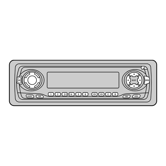
Page 72: Operations And Specifications
DEH-P7300R,P6300R 8. OPERATIONS AND SPECIFICATIONS 8.1 OPERATIONS Head Unit VOLUME OPEN button 5/∞/2/3 buttons EQ button SFEQ button SELECT SFEQ AUDIO button SOURCE AUDIO DISP FUNC FUNCTION button Buttons 1–6 BAND button DISPLAY button ENTERTAINMENT button TEXT button SOURCE button TA button Steering Remote Controller A steering remote controller that enables remote operation of the head unit is supplied.*... - Page 73 DEH-P7300R,P6300R...
- Page 74 DEH-P7300R,P6300R...
- Page 75 DEH-P7300R,P6300R...
- Page 76 DEH-P7300R,P6300R...
-
Page 77: Specifications
DEH-P7300R,P6300R 8.2 SPECIFICATIONS General CD player Power source ..14.4 V DC (10.8 – 15.1 V allowable) System ........Compact disc audio system Grounding system ........Negative type Usable discs ..........Compact disc Max. current consumption ........10.0 A Signal format ....Sampling frequency: 44.1 kHz Backup current ..........
Need help?
Do you have a question about the DEH-P7300R/X1N/EW and is the answer not in the manual?
Questions and answers