Table of Contents
Advertisement
Baked
Dinner
Rolls &
Frozen
Compu
Popcorn
Vegetables
Potatoes
Plate
Muffins
Entrees
Defost
Instant Action
NO.
LBS.
Ground
Chicken
MIcrowave
Kitchen Timer
CUPS
Casserole
Beverage
OZ
Meat
Breast
Pizza
Clock
COOK DEFROST
BEFORE SERVICING ...................................................................................................... INSIDE FRONT COVER
WARNING TO SERVICE PERSONNEL ................................................................................................................ 1
MICROWAVE MEASUREMENT PROCEDURE ................................................................................................... 2
FOREWORD AND WARNING ............................................................................................................................... 3
PRODUCT SPECIFICATIONS .............................................................................................................................. 4
GENERAL INFORMATION ................................................................................................................................... 4
OPERATION .......................................................................................................................................................... 6
TROUBLESHOOTING GUIDE .............................................................................................................................. 9
TEST PROCEDURE ............................................................................................................................................ 10
TOUCH CONTROL PANEL ................................................................................................................................. 18
COMPONENT REPLACEMENT AND ADJUSTMENT PROCEDURE ................................................................ 22
PICTORIAL DIAGRAM ........................................................................................................................................ 29
POWER UNIT CIRCUIT ...................................................................................................................................... 30
CPU UNIT CIRCUIT ............................................................................................................................................ 31
PRINTED WIRING BOARD ................................................................................................................................. 32
PARTS LIST ........................................................................................................................................................ 33
PACKING AND ACCESSORIES ......................................................................................................................... 37
SHARP CORPORATION
SERVICE MANUAL
Power
Minute Plus
1
2
3
4
5
Level
START
STOP
6
7
8
9
0
Clear
In the interest of user-safety the oven should be restored to its
original condition and only parts identical to those specified should
be used.
WARNING TO SERVICE PERSONNEL: Microwave ovens con-
tain circuitry capable of producing very high voltage and
current, contact with following parts may result in a severe,
possibly fatal, electrical shock. (High Voltage Capacitor, High
Voltage Power Transformer, Magnetron, High Voltage Recti-
fier Assembly, High Voltage Harness etc..)
TABLE OF CONTENTS
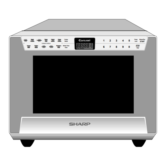
MICROWAVE OVEN
R-360EG
MODELS
R-360ES
R-360EW
R-360EZ
This document has been published to be used for after
sales service only.
The contents are subject to change without notice.
R- 360EG
R - 3 60 E S
R-360EW
R - 3 6 0 E Z
S3107R360EPW/
Page
Advertisement
Table of Contents

Related Manuals for Sharp R-360EG


Summary of Contents for Sharp R-360EG
-
Page 1: Table Of Contents
R- 360EG R - 3 60 E S R-360EW R - 3 6 0 E Z SERVICE MANUAL S3107R360EPW/ MICROWAVE OVEN R-360EG MODELS R-360ES Baked Dinner Rolls & Frozen Compu Power Minute Plus Popcorn Vegetables Potatoes Plate Muffins Entrees Defost... -
Page 2: Precautions To Be Observed Before And During Servicing To Avoid Possible Exposure To Excessive Microwave Energy
Before servicing an operative unit, perform a microwave emission check as per the Microwave Measurement Procedure outlined in this service manual. If microwave emissions level is in excess of the specified limit, contact SHARP ELECTRONICS CORPORATION immediately @1-800-237-4277. If the unit operates with the door open, service person should 1) tell the user not to operate the oven and 2) contact SHARP ELECTRONICS CORPORATION and Food and Drug Administration's Center for Devices and Radiological Health immediately. -
Page 3: Warning To Service Personnel
R-360EG R-360ES R-360EW R- 360EZ WARNING TO SERVICE PERSONNEL Microwave ovens contain circuitry capable of pro- ducing very high voltage and current, contact with following parts may result in a severe, possibly fatal, electrical shock. (Example) High Voltage Capacitor, High Voltage Power Trans- former, Magnetron, High Voltage Rectifier Assem- bly, High Voltage Harness etc.. -
Page 4: Microwave Measurement Procedure
MICROWAVE MEASUREMENT PROCEDURE A. Requirements: 1) Microwave leakage limit (Power density limit): The power density of microwave radiation emitted by a microwave oven should not exceed 1mW/cm at any point 5cm or more from the external surface of the oven, measured prior to acquisition by a purchaser, and thereafter (through the useful life of the oven), 5 mW/cm at any point 5cm or more from the external surface of the oven. - Page 5 PRODUCT DESCRIPTION MICROWAVE OVEN R-360EG/ R-360ES/ R-360EW/ R-360EZ GENERAL INFORMATION FOREWORD This Manual has been prepared to provide Sharp Electronics Corp. Service Personnel with Operation and Service Information for the SHARP MICROWAVE OVEN, R-360EG, R-360ES, R-360EW, R- OPERATION 360EZ. It is recommended that service personnel carefully study the entire...
-
Page 6: General Information
SPECIFICATION ITEM DESCRIPTION Power Requirements 120 Volts / 13.5 Amperes 60 Hertz Single phase, 3 wire grounded Power Output 1000 watts (IEC TEST PROCEDURE) Operating frequency of 2450MHz Case Dimensions Width 16-7/8" Height 13-3/8" Depth 18-3/4" Cooking Cavity Dimensions Width 13-3/4" Height 7-1/4"... -
Page 7: Oven Diagram
R-360EG R-360ES R-360EW R- 360EZ contact a qualified electrician and have it replaced with a properly Grounded 3-Pronged Plug grounded three-pronged wall receptacle or have a grounding adapter Receptacle Box properly grounded and polarized. If the extension cord must be used, it should be a 3-wire, 15 amp. -
Page 8: Operation
OPERATION DESCRIPTION OF OPERATING SEQUENCE The following is a description of component functions during relay (RY2) and is mechanically associated with the door oven operation. so that it will function in the following sequence. (1) When the door opens from the closed position, the OFF CONDITION secondary interlock relay (RY2) and primary interlock switch open their contacts. -
Page 9: Oven Schematic-Cooking Condition
R-360EG R-360ES R-360EW R- 360EZ SCHEMATIC NOTE: CONDITION OF OVEN 1. DOOR CLOSED 2. CLOCK APPEARS ON DISPLAY NOTE: " " indicates components with potential above 250V. OVEN THERMAL MONITOR MG. THERMAL CUT-OUT CUT-OUT FUSE 20A POWER TRANSFORMER N.O. SECONDARY... - Page 10 DESCRIPTION AND FUNCTION OF COMPONENTS DOOR OPEN MECHANISM CAUTION: BEFORE REPLACING A BLOWN MONITOR FUSE TEST THE DOOR SENSING SWITCH, The door is opened by pulling the door. Refer to the Figure SECONDARY INTERLOCK RELAY (RY2), D-1. RELAY (RY1), PRIMARY INTERLOCK Door SWITCH AND MONITOR SWITCH FOR Latch Hook...
-
Page 11: Troubleshooting Guide
R-360EG R-360ES R-360EW R- 360EZ TROUBLESHOOTING GUIDE Never touch any part in the circuit with your hand or an uninsulated tool while the power supply is connected. When troubleshooting the microwave oven, it is helpful to follow the Sequence of Operation in performing the checks. Many of the possible causes of trouble will require that a specific test be performed. -
Page 12: Test Procedure
CK = Check / RE = Replace RE RE A B C D E F F G H RE RE CK I CK CK CK J K L M TEST PROCEDURE PROBLEM CONDITION Home fuse or circuit breaker blows when power cord is plugged into wall receptacle. - Page 13 R-360EG R-360ES R-360EW R- 360EZ TEST PROCEDURES PROCEDURE COMPONENT TEST LETTER 4. To test for an open filament, isolate the magnetron from the high voltage circuit. A continuity check across the magnetron filament leads should indicate less than 1 ohm.
- Page 14 TEST PROCEDURES PROCEDURE COMPONENT TEST LETTER HIGH VOLTAGE RECTIFIER TEST 1. Disconnect the power supply cord, and then remove outer case. 2. Open the door and block it open. 3. Discharge the high voltage capacitor. 4. Isolate the rectifier from the circuit. Using the highest ohm scale of the meter, read the resistance across the terminals and observe, reverse the leads to the rectifier terminals and observe meter reading.
- Page 15 R-360EG R-360ES R-360EW R- 360EZ TEST PROCEDURES PROCEDURE COMPONENT TEST LETTER CAUTION: IF THE THERMAL CUT-OUT INDICATES AN OPEN CIRCUIT AT ROOM TEMPERATURE, REPLACE THERMAL CUT-OUT. PRIMARY INTERLOCK SWITCH TEST 1. Disconnect the power supply cord, and then remove outer case.
- Page 16 TEST PROCEDURES PROCEDURE COMPONENT TEST LETTER 5. Reconnect all leads removed from components during testing. 6. Reinstall the outer case (cabinet). 7. Reconnect the power supply cord after the outer case is installed. 8. Run the oven and check all functions.
- Page 17 R-360EG R-360ES R-360EW R- 360EZ TEST PROCEDURES PROCEDURE COMPONENT TEST LETTER 2-1 In connection with pads. a) When touching the pads, a certain group of pads do not produce a signal. b) When touching the pads, no pads produce a signal.
- Page 18 TEST PROCEDURES PROCEDURE COMPONENT TEST LETTER RELAY TEST 1. Disconnect the power supply cord, and then remove outer case. 2. Open the door and block it open. 3. To discharge the high voltage capacitor, wait for 60 seconds. 4. Disconnect the leads to the primary of the power transformer. 5.
- Page 19 R-360EG R-360ES R-360EW R- 360EZ TEST PROCEDURES PROCEDURE COMPONENT TEST LETTER STEPS OCCURRENCE CAUSE OR CORRECTION Only pattern at "a" is broken. *Insert jumper wire J1 and solder. Pattern at "a" and "b" are broken. *Insert the coil RCILF2003YAZZ between "c" and "d".
-
Page 20: Touch Control Panel
TOUCH CONTROL PANEL ASSEMBLY OUTLINE OF TOUCH CONTROL PANEL 3) Power Source Circuit The control unit section consists of the following units. This circuit generates voltages necessary in the control unit from the AC line voltage. (1) Key Unit In addition, the synchronizing signal is available in order (2) Control Unit (The Control Unit consists of Power Unit to compose a basic standard time in the clock circuit. - Page 21 R-360EG R-360ES R-360EW R- 360EZ Pin No. Signal Description 11-13 P57-P55 Terminal not used. CNTR0 Signal to sound buzzer (2.0 kHz). 0.1 sec. H : GND A: key touch sound. L : -5V B: Completion sound. 2.0 sec. H : GND L : -5V Terminal not used.
- Page 22 Pin No. Signal Description Power source voltage: -5.0V. VC voltage of power source circuit input. Terminal not used. Key strobe signal. Signal applied to touch-key section. A pulse signal is input to P43-P46 terminal while one of G7 line keys on key matrix is touched. Key strobe signal.
- Page 23 R-360EG R-360ES R-360EW R- 360EZ TOUCH CONTROL PANEL SERVICING transformer. 1. Precautions for Handling Electronic Components 4) Re-install the outer case (cabinet). This unit uses CMOS LSI in the integral part of the 5) Re-connect the power supply cord after the outer circuits.
-
Page 24: Component Replacement And Adjustment Procedure
WARNING FOR WIRING To prevent an electric shock, take the following pre- and Oven cavity. cautions. 3) Sharp edge: 1. Before wiring, Base plate, Oven cavity, Waveguide flange, Angles, 1) Disconnect the power supply cord. Guides and other metallic plates. -
Page 25: Pictorial Diagram
R-360EG R-360ES R-360EW R- 360EZ 6. Lift entire outer case from the unit. COMPONENTS OR WIRING. CAUTION: 1. DISCONNECT OVEN FROM POWER SUP NOTE: When replacing the outer case, the 2 special PLY BEFORE REMOVING OUTER CASE. Torx screws must be reinstalled in the same 2. - Page 26 transformer from the high voltage capacitor. 9. Remove the capacitor holder. The capacitor is now free. 6. Remove one (1) screw holding capacitor holder to base CAUTION: WHEN REPLACING HIGH VOLTAGE RECTI- plate. FIER AND HIGH VOLTAGE CAPACITOR, 7. Remove one (1) screw holding high voltage rectifier GROUND SIDE TERMINAL OF THE HIGH assembly to capacitor holder.
-
Page 27: Power Unit Circuit
5. Disconnect wire leads from turntable motor. CAUTION: NO SHARP EDGES MUST BE EVIDENT AF- (See "Positive lock connector removal") TER REMOVAL OF THE TURNTABLE MO- 6. Remove two (2) screws holding turntable motor to oven TOR COVER. - Page 28 DOOR SENSING SWITCH/PRIMARY INTERLOCK SWITCH AND MONITOR SWITCH REMOVAL Reinstallation 1. Disconnect the power supply cord and remove outer case. 1. Re-install each switch in its place. The primary interlock/ 2. Open the door and block it open. monitor switches are in the lower position and the door 3.
- Page 29 R-360EG R-360ES R-360EW R- 360EZ NOTE: When carrying out any repair to the door, do not Upper oven bend or warp the slit choke (tabs on the door hinge panelassembly) to prevent microwave leakage. 11.Release two (2) pins of door panel from two (2) holes of...
-
Page 30: Cpu Unit Circuit
CPU UNIT Hole of PWB cover PWB Cover 7. Remove the two (2) screws holding the PWB cover to the door frame assembly. 8. Remove the PWB cover from the door frame assembly. 9. Remove the one (1) screw holding the CPU unit to the door frame assembly. - Page 31 R-360EG R-360ES R-360EW R- 360EZ RECTIFIER H.V.
- Page 32 D1-D4 1N4002 CN-C – – C21 10 /35v AC(N) OVEN LAMP TURNTABLE OVEN LAMP MOTOR TURNTABLE FAN MOTOR MOTOR DTD143ES FAN MOTOR PKM22EPT BUZZER AC(H) R4 3.3k 1/4w MICRO MICRO CN-B DTA143ES DOOR D20 1SS270A DOOR SENSING SENSING SWITCH SWITCH D40 1SS270A...
- Page 33 R-360EG R-360ES R-360EW R- 360EZ SEG21 SEG21 SEG20 SEG20 SEG19 SEG19 SEG18 SEG18 SEG17 SEG17 SEG16 SEG16 SEG15 SEG15 SEG14 SEG14 SEG13 SEG13 SEG12 SEG12 SEG11 SEG11 SEG10 SEG10 SEG9 SEG9 SEG8 SEG8 SEG7 SEG7 SEG6 SEG6 SEG5 SEG5 SEG4...
-
Page 34: Printed Wiring Board
(J1) Figure S-4. Printed Wiring Board of Power Unit... -
Page 35: Parts List
Outer case cabinet [R-360ES] 2- 4 GCABUA805WRPZ Outer case cabinet [R-360EW] 2- 4 GCABUA807WRPZ Outer case cabinet [R-360EZ] 2- 4 GCABUA809WRPZ Outer case cabinet [R-360EG] POWER UNIT PARTS 3- 1 DPWBFC174WRUZ Power unit 3- 1A QCNCMA431DRE0 2-pin connector (CN-B) 3- 1B... - Page 36 To have your order filled promptly and correctly, please furnish the following information. 1. MODEL NUMBER 2. REF. NO. 3. PART NO. 4. DESCRIPTION Order Parts from the authorized SHARP parts Distributor for your area. Defective parts requiring return should be returned as indicated in the Service Policy.
-
Page 37: Oven And Cabinet Parts
R- 360EG R - 3 60 E S R-360EW R - 3 6 0 E Z OVEN AND CABINET PARTS 7-13 4-17 7-14 4-18 4-26 1-13 4-25 4-24 4-28 7-14 4-27 7-12 4-19 7-13 7-11 4-21 4-23 7-11 7-15 4-22 4-16 7-11 4-11... - Page 38 R- 360EG R - 3 6 0 E S R-360EW R - 3 6 0 E Z DOOR PARTS 5-10 5-13 5-11 5-13 5-12 5-12 5-14 5-12 5-12 5-3-1 5-3-2 MISCELLANEOUS (CAPACITOR) Actual wire harness may be different from illustration.
-
Page 39: Packing And Accessories
SPAKHA017WREZ 6- 7 INSTRUCTION BOOK & PRINTING MATTER BOTTOM PAD ASSEMBLY 6- 2 TURNTABLE TRAY FPADBA452WRKZ 6- 1 TURNTABLE SUPPORT TRAY PAD INTO THE SPADFA499WREZ OVEN CAVITY Not replaceable items. PACKING CASE SPAKCD562WREZ [R-360ES] SPAKCD569WREZ [R-360EW] SPAKCD570WREZ [R-360EZ] SPAKCD571WREZ [R-360EG]... - Page 40 No part of this publication may be reproduced, stored in retrieval systems, or transmitted in any form or by any means, electronic, mechanical, photocopying, recording, or otherwise, without prior written permission of the publisher. 2001 SHARP CORP. (3S2.530E) Printed in U.S.A...
Need help?
Do you have a question about the R-360EG and is the answer not in the manual?
Questions and answers