Table of Contents
Advertisement
Quick Links
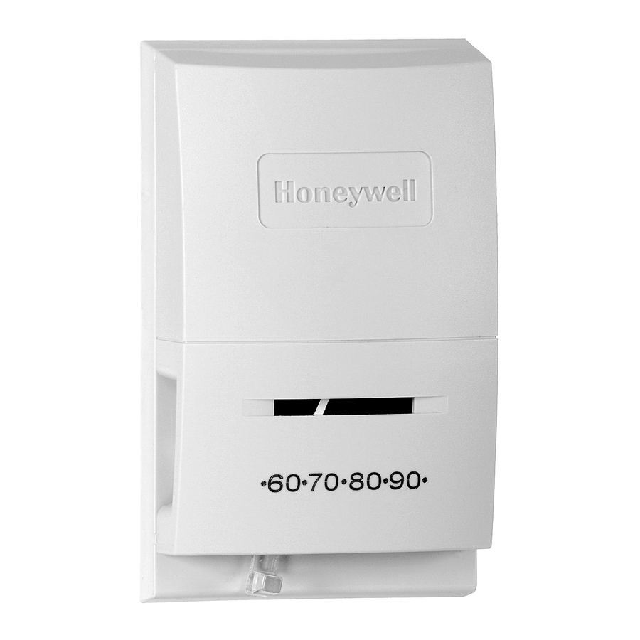
T822A,D,F,G; TS822A; and T8022D
T822A,D,F, TS822A, and T8022D Thermostats pro-
vide control of heating systems. T822G provides control of
AC heating or cooling appliances.
The T822A two-wire switch thermostat provides low
voltage control of heating systems and features a fixed heat
anticipator.
The T822D and T8022D two-wire, mercury switch
thermostat provides low voltage control of heating systems
and features an adjustable heat anticipator.
The T822F three-wire, mercury switch thermostat pro-
vides low voltage control of heating systems and features
an adjustable heat anticipator and AUTO-ON fan switch-
ing.
The T822G three-wire, mercury switch thermostat pro-
vides low voltage control of AC heating and cooling appli-
ances and features an adjustable heating anticipator and
nonadjustable cooling anticipator.
The TS822A two-wire, mercury switch thermostat pro-
vides millivoltage control of heating systems.
T822A,D; TS822A, and T8022D Thermostats are avail-
able with a positive OFF switch. All models are available
with temperature range stops.
M3375
If this control is replacing a control that contains mer-
cury in a sealed tube, do not place your old control in
thetrash.
Contact your local waste management authority for
instructions regarding recycling and the proper disposal of
this control, or of an old control containing mercury in a
sealed tube.
If you have questions, call Honeywell Inc. at
1-800-468-1502.
WHEN INSTALLING THIS PRODUCT...
1. Read these instructions carefully. Failure to follow
them could damage the product or cause a hazardous condi-
tion.
2. Check the ratings given in the Instructions and on the
product to make sure the product is suitable for your
application.
3. Installer must be a trained, experienced service tech-
nician.
4. After installation is complete, check out product
operation as provided in these Instructions.
CAUTION
Low Voltage Thermostats
Application
Recycling Notice
Installation
J. H. • Rev. 2-01 •
CAUTION
Disconnect power supply before beginning instal-
lation to prevent electrical shock or equipment
damage.
LOCATION
Locate the thermostat about 5 ft [1.5 m] above the floor
on an inside wall in an area with good air circulation at
average temperature.
Do not mount the thermostat where it can be affected by:
— drafts or dead spots behind doors or in corners.
— hot or cold air from ducts.
— concealed pipes and chimneys.
— radiant heat from the sun, fireplaces, or appliances.
— unheated (uncooled) areas behind the thermostat,
such as an outside wall.
MOUNTING AND WIRING
Disconnect power supply before beginning installation
to prevent electrical shock or equipment damage.
All wiring must comply with local codes and ordi-
nances.
T822A,D,F,G and TS822A Thermostats are designed to
be mounted vertically on a wall or a vertical outlet box.
T8022D is designed to be mounted horizontally on a wall.
In a 250 or 500 mV application, use No. 14 wire if
possible and make the run as short as possible; remember
this when selecting a location. For maximum wire lengths
of a 750 mV application, see Table 1.
TABLE 1—WIRE LENGTH.
Wire
Max. Length
Size
2-Wire Cable
ft
No. 18
30
No. 16
50
No. 14
80
1. In replacement applications, check the existing ther-
mostat wires for cracked or frayed insulation. Replace any
wires in poor condition. If the wire is plastered into the
wall, make a hole next to the wires and loosen the wires so
they can be pushed back into the wall later.
2. In new installations, run wiring (if necessary) to the
thermostat location.
3. Connect the wires to the terminals on the back of the
thermostat. See Figs. 1 through 6 for internal schematics
and typical hookup diagrams.
1
• ©Honeywell Inc. 2001 • Form Number 69-0510—4
M3375
Max. Combined
Length
2-Single Wires
m
ft
m
9.0
60
18.0
15.0
100
30.0
24.5
160
40.0
69-0510—4
Advertisement
Table of Contents

Subscribe to Our Youtube Channel
Related Manuals for Honeywell T8022D


Summary of Contents for Honeywell T8022D
- Page 1 T822A,D,F,G and TS822A Thermostats are designed to be mounted vertically on a wall or a vertical outlet box. T8022D is designed to be mounted horizontally on a wall. In a 250 or 500 mV application, use No. 14 wire if possible and make the run as short as possible;...
- Page 2 T822A,D; T8022D TEMP. FALL ANTICIPATOR CONTROL POWER SUPPLY. PROVIDE DISCONNECT MEANS AND OVERLOAD PROTECTION AS REQUIRED. T822D, T8022D ADJUSTABLE HEAT ANTICIPATOR. T822A HAS A FIXED HEAT ANTICIPATOR. Fig. 3—T822A,D and T8022D in typical oil heating application. T822A,D; T8022D TEMP. FALL ANTICIPATOR POWER SUPPLY.
- Page 3 NOTE: For best performance, the heat anticipator may (IF USED) MILLIVOLTAGE GENERATOR CAUTION M1294 IMPORTANT: The T822A,D,F, TS822A, and T8022D controlled by the thermostat. above room temperature. below room temperature. ously. desired settings. NOTE: To prevent compressor short cycling, install a five 9.
- Page 4 3. Replace the cover and wait five minutes for the cover and the thermostat to lose the heat it has gained from your hands. If the thermometer pointer and the setting lever indicator read approximately the same, no recalibration is needed.
Need help?
Do you have a question about the T8022D and is the answer not in the manual?
Questions and answers