Pioneer KEH-P8010R Service Manual

Pioneer KEH-P8010R Service Manual

Multi-cd/dab control high power cassette player with rds tuner multi-cd control high power cassette player with fm/am tuner
Hide thumbs Also See for KEH-P8010R:

Advertisement

Service
Manual
MULTI-CD/DAB CONTROL HIGH POWER CASSETTE PLAYER WITH RDS TUNER
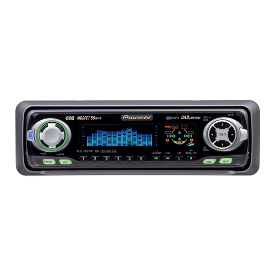
KEH-P8010R
MULTI-CD CONTROL HIGH POWER CASSETTE PLAYER WITH FM/AM TUNER
KEH-P8015
- This service manual should be used together with the following manual(s):
Model No.
Order No.
CX-1011
CRT2406
NOTE:
- Dolby noise reduction manufactured under license from Dolby Laboratories Licensing Corporation.
"Dolby" and the double-D symbol are trademarks of Dolby Laboratories Licensing Corporation.
-
This service manual does not describe the CD test mode.
For the operations in the CD test mode, refer to the CD player's Service manual.
-
Extension cable of cassette mechanism : Jig No. GGD1121
CONTENTS
1. SAFETY INFORMATION ............................................2
2. EXPLODED VIEWS AND PARTS LIST .......................2
4. PCB CONNECTION DIAGRAM ................................32
5. ELECTRICAL PARTS LIST ........................................40
6. ADJUSTMENT..........................................................49
PIONEER CORPORATION
PIONEER ELECTRONICS SERVICE INC.
PIONEER EUROPE NV
Haven 1087 Keetberglaan 1, 9120 Melsele, Belgium
PIONEER ELECTRONICS ASIACENTRE PTE.LTD. 253 Alexandra Road, #04-01, Singapore 159936
C PIONEER CORPORATION 2001
KEH-P8010R/X1N/EW
EQ
SOURCE
DISP
Mech. Module Remarks
3L
Cassette Mech. Module:Mech.Description, Disassembly, Adjustment
4-1, Meguro 1-Chome, Meguro-ku, Tokyo 153-8654, Japan
P.O.Box 1760, Long Beach, CA 90801-1760 U.S.A.
SELECT
SFEQ
1
2
3
4
5
6
E
B
FUNC
AUDIO
X1N/ES
7. GENERAL INFORMATION .......................................51
7.1 DIAGNOSIS ........................................................51
7.1.1 DISASSEMBLY .........................................51
7.1.2
7.2 IC .........................................................................55
7.3 OPERATIONAL FLOW CHART ...........................61
8. OPERATIONS AND SPECIFICATIONS.....................62
ORDER NO.
CRT2621
X1N/EW
.......53
K-ZZA. FEB. 2001 Printed in Japan

Advertisement

Table of Contents
loading

Summary of Contents for Pioneer KEH-P8010R

  • Page 1: Table Of Contents

    PIONEER ELECTRONICS SERVICE INC. P.O.Box 1760, Long Beach, CA 90801-1760 U.S.A. PIONEER EUROPE NV Haven 1087 Keetberglaan 1, 9120 Melsele, Belgium PIONEER ELECTRONICS ASIACENTRE PTE.LTD. 253 Alexandra Road, #04-01, Singapore 159936 C PIONEER CORPORATION 2001 K-ZZA. FEB. 2001 Printed in Japan...
  • Page 2: Safety Information

    If you are not qualified to perform the repair of this product properly and safely, you should not risk trying to do so and refer the repair to a qualified service technician. 2. EXPLODED VIEWS AND PARTS LIST 2.1 PACKING(KEH-P8010R/X1N/EW)
  • Page 3 KEH-P8010R,P8015 NOTE: - Parts marked by “*” are generally unavailable because they are not in our Master Spare Parts List. - Screws adjacent to mark on the product are used for disassembly. - PACKING SECTION PARTS LIST Mark No. Description Part No.
  • Page 4 KEH-P8010R,P8015 2.2 PACKING(KEH-P8015/X1N/ES) - PACKING SECTION PARTS LIST Mark No. Description Part No. Mark No. Description Part No. 1 Carton CHG4332 16 Protector CHP2252 2 Cord Assy CDE6438 17 Protector CHP2251 3 Accessory Assy CEA2395 18 Case Assy CXB3520 4 Spring...
  • Page 5 KEH-P8010R,P8015 - Owner's Manual, Installation Manual Model Part No. Language KEH-P8015/X1N/ES CRD3368 English, Spanish, Portuguese(B) CRD3369 Arabic, Chinese CRD3370 English, Spanish, Portuguese(B), Arabic, Chinese...
  • Page 6 KEH-P8010R,P8015 2.3 EXTERIOR(KEH-P8010R/X1N/EW)
  • Page 7 KEH-P8010R,P8015 - EXTERIOR SECTION PARTS LIST Mark No. Description Part No. Mark No. Description Part No. 1 Screw BMZ30P040FZK 51 Arm CNV6508 2 Screw BMZ30P100FMC 52 Panel Unit CWM7627 3 Screw BSZ26P060FMC 53 Socket(CN1950) CKS3550 4 Screw BSZ30P040FMC 54 Connector(CN1951)
  • Page 8 KEH-P8010R,P8015 2.4 EXTERIOR(KEH-P8015/X1N/ES)
  • Page 9 KEH-P8010R,P8015 - EXTERIOR SECTION PARTS LIST Mark No. Description Part No. Mark No. Description Part No. 1 Screw BMZ30P040FZK 51 Arm CNV6508 2 Screw BMZ30P100FMC 52 Panel Unit CWM7627 3 Screw BSZ26P060FMC 53 Socket(CN1950) CKS3550 4 Screw BSZ30P040FMC 54 Connector(CN1951)
  • Page 10 KEH-P8010R,P8015 2.5 CASSETTE MECHANISM MODULE...
  • Page 11 KEH-P8010R,P8015 - CASSETTE MECHANISM MODULE SECTION PARTS LIST Mark No. Description Part No. Mark No. Description Part No. 1 Screw BSZ20P040FMC 46 Pinch Roller ENV1518 2 Washer CBF1037 47 Pinch Holder Unit EXA1607 3 Washer CBG1003 48 Pinch Roller ENV1518...
  • Page 12: Block Diagram And Schematic Diagram

    KEH-P8010R,P8015 3. BLOCK DIAGRAM AND SCHEMATIC DIAGRAM 3.1 BLOCK DIAGRAM TUNER AMP UNIT FM/AM TUNER UNIT Q153 Q151 Q155 FM/AM 1ST IF 10.7MHz MPXREF 41kHz CN401 AMRF T51 Q51 CF51 CF52 CF53 AMDET AMANT L ch IC 2 FM MPX...
  • Page 13: Keyboard Unit

    KEH-P8010R,P8015 RESET CN351 IC 961 PRE OUT L S-80735ANDZI Q351 CN352-1 TMUTE Q352 fm/AM SYSTEM -COM Q353 IC 601(1/2) CN352-2 PD5616A(EW) ldet PD5617A(ES) Q911 NL2DT Q931 bsens SDBW TUNPCE asens TUNPCK tunpce@ TUNPDO ASENBO CN901 30 29 81 ELECTRONIC VOLUME/...
  • Page 14 KEH-P8010R,P8015 3.2 OVERALL CONNECTION DIAGRAM(GUIDE PAGE)(KEH-P8010R/X1N/EW) Note: When ordering service parts, be sure to refer to “EXPLODED VIEWS AND PARTS LIST” or “ELECTRICAL PARTS LIST”. Large size SCH diagram Guide page TAPE(0dB):-11.2dBs Detailed page IP-BUS CN251 DRIVER > PANEL UNIT...
  • Page 15 KEH-P8010R,P8015 TUNER AMP UNIT FM(100%): -16.5dBs FM(100%):+5.84dBs AM(30%): -27.0dBs AM(30%): -2.66dBs IP-BUS: +2.2dBs FM(100%): +6.6dBs IP-BUS:+8.54dBs TAPE:-11.24dBs AM(30%): -1.9dBs TAPE: -4.9dBs IP-BUS: +9.3dBs TAPE:-4.14dBs RESET 600 H > FUSE CEK1136 FM(100%): +32.6dBs AM(30%): +24.1dBs IP-BUS: +35.3dBs TAPE:+21.86dBs RR– BACK UP FR–...
  • Page 16 KEH-P8010R,P8015 IP-BUS:+2.2dBs 0%):-26.0dBs 0%):-15.5dBs TEL/MIC...
  • Page 17 KEH-P8010R,P8015 SENSE DETACH CN1901 UNIT KEYBOARD AM(30%):-26.0dBs UNIT TUNER FM/AM FM(100%):-15.5dBs...
  • Page 18 KEH-P8010R,P8015...
  • Page 19 KEH-P8010R,P8015...
  • Page 20 KEH-P8010R,P8015 3.3 OVERALL CONNECTION DIAGRAM(GUIDE PAGE)(KEH-P8015/X1N/ES) Note: When ordering service parts, be sure to refer to “EXPLODED VIEWS AND PARTS LIST” or “ELECTRICAL PARTS LIST”. TAPE(0dB):-11.2dBs IP-BUS CN251 DRIVER FM(1 PANEL UNIT EJECT SW...
  • Page 21 KEH-P8010R,P8015 TUNER AMP UNIT M(100%): -20.5dBs M(30%): -31.0dBs IP-BUS: +2.2dBs FM(100%): +2.6dBs TAPE:-11.24dBs AM(30%): -7.9dBs IP-BUS: +7.3dBs TAPE:-6.14dBs RESET 600 H > FUSE CEK1136 FM(100%): +28.6dBs AM(30%): +18.1dBs IP-BUS: +33.3dBs TAPE:+19.86dBs...
  • Page 22 KEH-P8010R,P8015 IP-BUS:+2.2dBs M(30%):-30.0dBs (100%):-19.5dBs...
  • Page 23 KEH-P8010R,P8015 SENSE DETACH CN1901 UNIT KEYBOARD AM(30%):-30.0 UNIT TUNER FM/AM FM(100%):-19.5 A-a B...
  • Page 24 KEH-P8010R,P8015...
  • Page 25 KEH-P8010R,P8015...
  • Page 26 KEH-P8010R,P8015 3.4 KEYBOARD UNIT(KEH-P8010R/X1N/EW) REMOTE CONTROL SENSOR VOLUME S1930 CSD1059 SFEQ CSG1113 CSG1147 CSG1147 CSG1115...
  • Page 27 KEH-P8010R,P8015 KEYBOARD UNIT GRILLE -COM OEL CONTROLLER OEL UNIT MXS8016...
  • Page 28 KEH-P8010R,P8015 3.5 KEYBOARD UNIT(KEH-P8015/X1N/ES) REMOTE CONTROL SENSOR VOLUME S1930 CSD1059 SFEQ CSG1146...
  • Page 29 KEH-P8010R,P8015 KEYBOARD UNIT GRILLE -COM OEL CONTROLLER OEL UNIT MXS8016...
  • Page 30: Cassette Mechanism Module

    KEH-P8010R,P8015 3.6 CASSETTE MECHANISM MODULE DECK UNIT CN252 C256 Rev-L Rev-R MUTE NF1(R) Vref1 120/70 IC251 ser/REP RIN(L) Fwd-R HA12228F MSOUT RIN(R) C405 R033 Fwd-L R404 270K MSDET FIN(R) C404 Vref2 Dolby-B R403 MAOUT FIN(L) NFI(L) MSGV(R) HEAD ASSY EXA1589...
  • Page 31 KEH-P8010R,P8015 M1 MOTOR UNIT (MAIN MOTOR) EXA1490 CN255 CN256 REEL SENSE CN253 EGN1 EGN1004 R375 R373 70 s ESG1007 MECHANISM MODE ESG1007 DRIVER load S1 LOAD ESG1007 REEL SENSE CN254 MOTOR UNIT (SUB MOTOR) VCC2 EXA1580 R374 C356 SWITCHES: REEL SENSE PCB C355 S1:LOAD SWITCH..EJECT-PLAY...
  • Page 32: Pcb Connection Diagram

    KEH-P8010R,P8015 FRONT OUTPUT, TUNER AMP UNIT REAR OUTPUT 4. PCB CONNECTION DIAGRAM CORD ASSY MIC, TEL 4.1 TUNER AMP UNIT NOTE FOR PCB DIAGRAMS 1. The parts mounted on this PCB include all necessary parts for several destination. For further information for...
  • Page 33 KEH-P8010R,P8015 SIDE A IC, Q SWBWOOFER OUTPUT IP-BUS ANTENNA FRONT CN1950 CN251...
  • Page 34 KEH-P8010R,P8015 IC, Q TUNER AMP UNIT...
  • Page 35 KEH-P8010R,P8015 SIDE B...
  • Page 36 KEH-P8010R,P8015 4.2 PANEL UNIT SIDE A SIDE B...
  • Page 37 KEH-P8010R,P8015 4.3 KEYBOARD UNIT SIDE A SIDE B...
  • Page 38 KEH-P8010R,P8015 4.4 CASSETTE MECHANISM MODULE CN251 SIDE A DECK UNIT CN251 C271 SIDE B DECK UNIT HEAD ASSY IC,Q VR302 CN254 CN255 CN253 IC351 CN252 IC251 Q351 Q352 VR301 CN256...
  • Page 39 KEH-P8010R,P8015 REEL SENSE PCB LOAD 70 s MODE CN256 CN253 EGN1 REEL SENSE...
  • Page 40: Electrical Parts List

    KEH-P8010R,P8015 5. ELECTRICAL PARTS LIST NOTES: - Parts whose parts numbers are omitted are subject to being not supplied. - The part numbers shown below indicate chip components. Chip Resistor RS1/_S___J,RS1/__S___J Chip Capacitor (except for CQS..) CKS.., CCS.., CSZS..=====Circuit Symbol and No.===Part Name Part No.
  • Page 41 KEH-P8010R,P8015 =====Circuit Symbol and No.===Part Name Part No. =====Circuit Symbol and No.===Part Name Part No. ------ ------------------------------------------ ------------------------- ------ ------------------------------------------ ------------------------- RS1/16S223J RS1/16S223J RS1/16S223J RS1/16S223J RS1/16S102J RS1/16S223J RS1/16S102J RS1/16S223J RS1/16S224J RS1/16S0R0J RS1/16S224J RS1/16S0R0J RS1/16S104J RS1/16S0R0J RS1/16S102J RS1/16S0R0J RS1/16S104J RS1/16S0R0J RAB4C102J...
  • Page 42 KEH-P8010R,P8015 =====Circuit Symbol and No.===Part Name Part No. =====Circuit Symbol and No.===Part Name Part No. ------ ------------------------------------------ ------------------------- ------ ------------------------------------------ ------------------------- RS1/16S102J RD1/4PU153J RS1/16S225J RS1/16S472J RS1/16S681J RS1/16S472J RS1/16S0R0J RS1/16S102J RS1/16S104J RS1/16S102J RS1/16S102J RS1/16S822J RS1/16S102J RS1/16S473J RS1/16S102J RS1/16S104J RS1/16S102J RS1/16S473J RAB4C222J...
  • Page 43 KEH-P8010R,P8015 =====Circuit Symbol and No.===Part Name Part No. =====Circuit Symbol and No.===Part Name Part No. ------ ------------------------------------------ ------------------------- ------ ------------------------------------------ ------------------------- CKSRYB222K50 CEJQ470M10 CKSRYB222K50 330µF/10V CCH1181 CKSRYB222K50 CKSRYB103K50 CKSRYB222K50 CEJQ100M16 CKSRYB222K50 CEJQ100M16 CKSRYB222K50 CEAL2R2M50 CKSRYB182K50 CKSRYB473K25 Unit Number : CWM7462...
  • Page 44 KEH-P8010R,P8015 =====Circuit Symbol and No.===Part Name Part No. =====Circuit Symbol and No.===Part Name Part No. ------ ------------------------------------------ ------------------------- ------ ------------------------------------------ ------------------------- ZNR 451 Surge Protector DSP-201M-A21F RS1/16S0R0J Ferri-Inductor LAU2R2K RS1/16S0R0J Ferri-Inductor LAU4R7K RS1/16S0R0J Ferri-Inductor LAU1R0M RS1/16S103J Ferri-Inductor LAU2R2K RS1/16S103J Inductor...
  • Page 45 KEH-P8010R,P8015 =====Circuit Symbol and No.===Part Name Part No. =====Circuit Symbol and No.===Part Name Part No. ------ ------------------------------------------ ------------------------- ------ ------------------------------------------ ------------------------- RS1/16S222J CEAL1R0M50 RS1/16S222J CEALR22M50 RS1/16S222J CEALR22M50 RS1/16S222J CEAL1R0M50 RS1/16S473J CEAL1R0M50 RS1/16S104J CEAL1R0M50 RD1/4PU391J CEAL1R0M50 RS1/16S222J CEALNP4R7M16 RS1/16S222J CEALNP4R7M16 RS1/16S331J...
  • Page 46 KEH-P8010R,P8015 =====Circuit Symbol and No.===Part Name Part No. =====Circuit Symbol and No.===Part Name Part No. ------ ------------------------------------------ ------------------------- ------ ------------------------------------------ ------------------------- CEJQ470M10 1924 Push Switch CSG1113 330µF/10V CCH1181 1930 Encoder CSD1059 CKSRYB103K50 VR 1902 Semi-fixed 20k (B) CCP1231 CEJQ100M16 OEL Unit...
  • Page 47 KEH-P8010R,P8015 =====Circuit Symbol and No.===Part Name Part No. =====Circuit Symbol and No.===Part Name Part No. ------ ------------------------------------------ ------------------------- ------ ------------------------------------------ ------------------------- 1908 CKSRYB473K16 1923 Push Switch CSG1112 1913 CSZSR100M16 1924 Push Switch CSG1112 1922 CKSRYB104K16 1930 Encoder CSD1059 1926 CKSRYB104K25...
  • Page 48 KEH-P8010R,P8015 =====Circuit Symbol and No.===Part Name Part No. =====Circuit Symbol and No.===Part Name Part No. ------ ------------------------------------------ ------------------------- ------ ------------------------------------------ ------------------------- 1928 CKSRYB104K25 CKSRYB103K50 1929 CKSRYB104K16 CKSQYB104K50 1936 CKSRYB104K25 CKSRYB103K50 1937 CKSRYB104K16 CKSRYB392K50 1938 CKSRYB104K16 CKSRYB334K10 1941 CKSRYB104K16 CKSRYB223K25 1943 4.7µF/25V...
  • Page 49: Adjustment

    KEH-P8010R,P8015 6. ADJUSTMENT 6.1 OEL UNIT ADJUSTMENT - Adjustment point KEYBOARD UNIT (SIDE B) <When the OEL Unit has been replaced> 1. Use VR1902 to adjust the resistance between TP1 and TP2 to 5.85k .
  • Page 50 KEH-P8010R,P8015 6.2 DOLBY B NR ADJUSTMENT - Connection Diagram BACK UP +14.4V DC Regulated Power Supply GGD1121 Extention Cord TUNER AMP UNIT DECK UNIT VR302 VR301 Pin2 Pin3 CN251 L-CH R-CH Meter(1) DOLBY B NR ADJUSTMENT Test Tape Adjustment Point...
  • Page 51: General Information

    KEH-P8010R,P8015 7. GENERAL INFORMATION 7.1 DIAGNOSIS 7.1.1 DISASSEMBLY Removing the Case Unit(not shown) 1. Remove the Case Unit. Cassette Mechanism Module Removing the Cassette Mechanism Module (Fig.1) Remove the four screws and then remove the Cassette Mechanism Module. Removing the Panel Assy (Fig.1) Remove the two screws and then remove the Panel Assy.
  • Page 52 KEH-P8010R,P8015 - Removing the OEL Unit 1. Apply hot air to the cable pins for the anode terminal using a Anode terminal blower used for removing a flat-packaged IC or something like that. When all the pins are peeling off from the PCB, pinch the cable with a pair of tweezers and remove it slowly from the PCB.
  • Page 53: Connector Function Description

    KEH-P8010R,P8015 7.1.2 CONNECTOR FUNCTION DESCRIPTION KEH-P8010R/X1N/EW FRONT OUTPUT REAR OUTPUT FUSE 10A PRE OUTPUT 4 6 8 12 14 3 5 7 11 13 1. BUS+ 1. RR+ 2. GND 2. FR+ ANTENNA 3. GND 3. RR- 4. NC 4. FR- 5.
  • Page 54 KEH-P8010R,P8015 KEH-P8015/X1N/ES FRONT OUTPUT FUSE 10A PRE OUTPUT 4 6 8 12 14 3 5 7 11 13 1. BUS+ 1. RR+ 2. GND 2. FR+ ANTENNA 3. GND 3. RR- 4. NC 4. FR- 5. BUS- 5. RL+ 6. GND 6.
  • Page 55 KEH-P8010R,P8015 7.2 IC - Pin Functions (PD5616A, PD5617A) Pin No. Pin Name Function and Operation TUNPDO TUNER:Data output(PLL) TUNPCK TUNER:Clock output(PLL) EMUTE EVOL:Mute output EVOL:Strobe output EVOL:Data output Not used EVOL:Clock output BYTE CNVSS TELIN TEL:Cellular mute input HTELPW TEL:Microphone control output...
  • Page 56 KEH-P8010R,P8015 Pin No. Pin Name Function and Operation 3L:Position sense 3L:Reverse sense 3L:Normal sense Power supply input(Vcc) 3L:Sub-motor 2 Power supply input(Vss) 3L:Sub-motor 1 3L:Carriage motor STBY 3L:Drive IC control 68, 69 Not used(OPEN) htelm TEL:Mute output for handsfree tunpce@...
  • Page 57 KEH-P8010R,P8015 - Pin Functions (PD5627A) Pin No. Pin Name Function and Operation Not used OPEN Remote control reception BYTE GND connection CNVSS GND connection 8, 9 Not used OPEN RESET Pull up XOUT Crystal oscillating element connection pin VSS connection...
  • Page 58 KEH-P8010R,P8015 HA12228F MUTE ON/off NFI(R) Dolby B-NR 120/70 Vref1 MUTE ON/off ser/REP RIN(L) for/REV RIN(R) MSOUT MSDET FIN(R) Vref2 MUTE ON/off MAOUT FIN(L) Dolby B-NR MSGv(R) NFI(L) PML009A Isolator SEL_out_L SEL_out_R Treble Middle Bass Source Gain adjuster Primary PV_in_L Anti...
  • Page 59 KEH-P8010R,P8015 PAL006A sw_vcc amp_vcc sw_vcc stby 12 13 14 15 16 17 20 21 22 23 24 25 10 11 18 19 PD8074A A0-A19 :Address input D0-D15 :Data output byte :8/16 bit mode select :Chip enable input :Output enable input...
  • Page 60 KEH-P8010R,P8015 - FM/AM Tuner Unit FM/AM TUNER UNIT FM/AM 1ST IF 10.7MHz MPXREF 41kHz AMRF T51 Q51 CF51 CF52 CF53 AMDET AMANT L ch IC 2 FM MPX R ch ANT ADJ COMP MIXER, IF AMP, DET. LDET FMANT RFGND...
  • Page 61: Operational Flow Chart

    KEH-P8010R,P8015 7.3 OPERATIONAL FLOW CHART Power ON VCC=5V 16pin bsens 73pin bsens=L asens 74pin asens=L dsens 41pin dsens=L ASENBO H 82pin csens < < - CSENS 2V , 3V CSENS 93pin Source returns to the original one(before you open). 2V<CSENS<3V CD, MD and TAPE loading functions are available.
  • Page 62: Operations And Specifications

    KEH-P8010R,P8015 8. OPERATIONS AND SPECIFICATIONS 8.1 OPERATIONS Head Unit (for KEH-P8010R) VOLUME OPEN button 5/∞/2/3 buttons EQ button SFEQ button SELECT SFEQ AUDIO button SOURCE AUDIO DISP FUNC FUNCTION button Buttons 1–6 BAND button DISPLAY button ENTERTAINMENT button TEXT button...
  • Page 63 KEH-P8010R,P8015 Steering Remote Controller (for KEH-P8010R) The steering remote controller (CD-SR80) enabling remote control of the head unit is sold separately. Operation is the same as when using buttons on the head unit. ATT button This lets you quickly lower volume level (by about 90%).
  • Page 64 KEH-P8010R,P8015...
  • Page 65 KEH-P8010R,P8015...
  • Page 66 KEH-P8010R,P8015...
  • Page 67 KEH-P8010R,P8015...
  • Page 68: Specifications

    KEH-P8010R,P8015 8.2 SPECIFICATIONS - KEH-P8010R/X1N/EW General Cassette player Power source ..14.4 V DC (10.8 – 15.1 V allowable) Tape ......Compact cassette tape (C-30 – C-90) Grounding system ........Negative type Tape speed ..4.76 cm/sec. (+0.14 cm/sec., -0.05 cm/sec.) Max.
  • Page 69 KEH-P8010R,P8015 - KEH-P8015/X1N/ES General Cassette player Power source ..14.4 V DC (10.8 – 15.1 V allowable) Tape ......Compact cassette tape (C-30 – C-90) Grounding system ........Negative type Tape speed ..4.76 cm/sec. (+0.14 cm/sec., -0.05 cm/sec.) Max. current consumption ........10.0 A Fast forward/rewinding time ..

This manual is also suitable for:

Keh-p8015

Table of Contents