Table of Contents
Advertisement
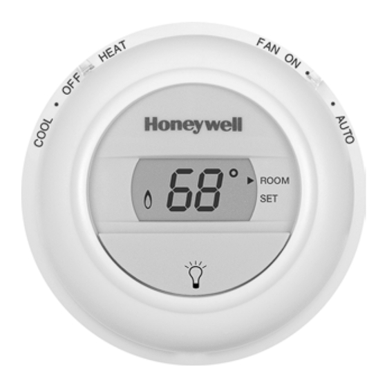
THE DIGITAL ROUND
CT8775A Heat Only Thermostat (20 to 30 Vac) and
CT8775C Heating-Cooling Thermostat (20 to 30 Vac)
Para obtener un documento con las instrucciones en español, por favor visite
nuestro sitio de web a: www.honeywell.com/yourhome.
Pour obtenir des notices techniques en français, veuillez consulter notre site web
www.honeywell.com/yourhome.
Contents
Step 1. Prepare for Installation ..................................................................................................................................
Step 2. Remove Old Thermostat ...............................................................................................................................
Step 3. Special Installations........................................................................................................................................
Step 4. Label Thermostat Wires .................................................................................................................................
Step 5. Separate Wallplate from Thermostat..............................................................................................................
Step 6. Mount Decorator Cover Plate and Thermostat Wallplate...............................................................................
Step 7. Wire Wallplate Terminals................................................................................................................................
Step 8. Customize the Thermostat ............................................................................................................................. 10
Step 9. Mount the Thermostat .................................................................................................................................... 11
Step 10. Set the System and Fan Switches ............................................................................................................... 12
Step 11. Operating the Thermostat............................................................................................................................. 13
Step 12. Check Operation of Heating and/or Cooling System ................................................................................... 13
If You Have A Problem ............................................................................................................................................... 15
Wiring Diagrams......................................................................................................................................................... 16
® U.S. Registered Trademark • Patents Pending
Copyright © 2004 Honeywell International Inc.
All Rights Reserved
™
NON-PROGRAMMABLE THERMOSTATS
CT8775A,C
OWNER'S GUIDE
3
4
4
5
5
5
8
69-1676-1
Advertisement
Table of Contents

Related Manuals for Honeywell THE DIGITAL ROUND CT8775A


Summary of Contents for Honeywell THE DIGITAL ROUND CT8775A
-
Page 1: Table Of Contents
THE DIGITAL ROUND CT8775A Heat Only Thermostat (20 to 30 Vac) and CT8775C Heating-Cooling Thermostat (20 to 30 Vac) Para obtener un documento con las instrucciones en español, por favor visite nuestro sitio de web a: www.honeywell.com/yourhome. Pour obtenir des notices techniques en français, veuillez consulter notre site web www.honeywell.com/yourhome. -
Page 2: Mercury Notice
This manual answers many of the questions that can arise as you become familiar and comfortable with your Honeywell thermostat — the state of the art in home comfort controls. Read these instructions carefully. Failure to follow these instructions can damage the product or cause a hazardous condition. -
Page 3: Step 1. Prepare For Installation
Baseboard Electric (120/240 line volt) Single Stage Heat Pump Multistage Heat Pumps/Multistage Equipment Compatible with 2-wire Honeywell zone valves. Not compatible with Taco zone valves and 2- or 3-wire White- Rodgers zone valves (No. 1311 and 1361). Not compatible with any 120/240 volt system. -
Page 4: Step 2. Remove Old Thermostat
Replacing a thermostat that has wires connected to C or C1 terminals If you are replacing a thermostat that has one or two wires connected to C or C1 terminals, do not allow them to touch, or you can damage the transformer. Wrap the wires separately using electrical tape. Place the wires where they will not interfere with the operation of the new thermostat. -
Page 5: Step 4. Label Thermostat Wires
ON, the CT8775C Thermostat will work with your system. Continue with the installation at Step 4. If you purchased a CT8775A thermostat, return the product to the place of purchase. The CT8775A thermostat is not compatible with this application. - Page 6 Mount Decorator Cover Plate (Optional) and Wallplate Directly to Wall If using the decorator cover plate, pull the wires through the wiring hole on the decorator cover plate. Position the decorator cover plate against the wall so that the UP indicator in the middle of the decorator cover plate is pointing up.
- Page 7 Mount Decorator Cover Plate (Required) and Wallplate onto Electrical Box Pull the wires through the wiring hole on the decorator cover plate. Place the decorator cover plate against the electrical box so that the UP indicator in the middle of the decorator cover plate is pointing up.
-
Page 8: Step 7. Wire Wallplate Terminals
Refer to the labels you placed on the wires when you removed the old thermostat (see illustration). Match the letter of your old thermostat wire with the corresponding terminal letter on your new thermostat. Refer to Table 2. IMPORTANT... - Page 9 468-1502. NOTES: If wires were connected to both Rh and R terminals on the old thermostat, remove jumper between R and Rc on the new thermostat and connect Rh to R and R to Rc. If wires will be connected to both R and Rc on the new thermostat, remove jumper between R and Rc.
-
Page 10: Step 8. Customize The Thermostat
DIP Switch To adjust the heat cycle rate or the Fahrenheit/Celsius indication, locate DIP switch 1, 2 and 3 on the back of the thermostat. See Fig. 4. Set Heat Cycle Rate Use DIP switches 1 and 2 to set the heat cycle rate. See Table 3. -
Page 11: Fahrenheit/Celsius Indication
Use DIP switch 3 to set the desired temperature indication. See Table 4. Fahrenheit/Celsius Display Fahrenheit (factory setting) Celsius STEP 9. MOUNT THE THERMOSTAT Table 3. Heat Cycle Rate. Cycles Per Hour DIP Switch 1 DIP Switch 2 Check with manufacturer for recommended cycle rate. -
Page 12: Step 10. Set The System And Fan Switches
STEP 10. SET THE SYSTEM AND FAN SWITCHES (CT8775C ONLY) System Switch (see Fig. 5) Heat: The thermostat controls your heating system. Off: Both the heating and cooling systems are off. Cool: The thermostat controls your cooling system. Fan Switch (see Fig. 5) Fan Auto: Normal setting for most homes. -
Page 13: Step 11. Operating The Thermostat
Turn the dial clockwise to raise the temperature setting several degrees above the room temperature. A flame will appear in the display to indicate the thermostat has called for heating. The heating system should turn on. Turn the dial counterclockwise to lower the temperature setting below the room temperature. -
Page 14: Cooling System
If a call for cooling is made before the compressor has been off for five minutes, or if a power interruption occurs while the compressor is running, the thermostat will go into a five-minute delay to protect the com- pressor. The snowflake After five minutes, the thermostat will display a solid snowflake The cooling system should turn on. -
Page 15: If You Have A Problem
Customer Assistance Please read and follow the provided instructions for this thermostat. For additional information, go to www.honeywell.com/yourhome or call Honeywell Customer Care, toll free, at 1-800-468-1502. Before calling, please have the following information available: •... -
Page 16: Wiring Diagrams
Wiring Diagrams HEATING RELAY OR VALVE COIL POWER SUPPLY. PROVIDE DISCONNECT MEANS AND OVERLOAD PROTECTION AS REQUIRED. 69-1676—1 1 POWER SUPPLY. PROVIDE DISCONNECT MEANS AND OVERLOAD PROTECTION AS REQUIRED. 2 FACTORY INSTALLED JUMPER. M19450 HEATING COMPRESSOR RELAY OR CONTACTOR VALVE COIL 1 POWER SUPPLY. - Page 17 3 USE A JUMPER WIRE (NOT SUPPLIED) TO CONNECT W TO Y. 4 USE EITHER O OR B FOR HEAT PUMP CHANGEOVER. Notice: This thermostat is a Class B digital apparatus that complies with Canadian Radio Interference Regulations, CRC c. 1374. HEAT...
-
Page 18: Limited One-Year Warranty
Golden Valley, MN 55422-3992 This warranty does not cover removal or reinstallation costs. This warranty shall not apply if it is shown by Honeywell that the defect or malfunction was caused by damage which occurred while the product was in the possession of a consumer. - Page 19 69-1676—1...
- Page 20 Automation and Control Solutions Honeywell International Inc. Honeywell Limited-Honeywell Limitée 1985 Douglas Drive North 35 Dynamic Drive Golden Valley, MN 55422 Scarborough, Ontario M1V 4Z9 69-1676—1 J.S. Rev. 6-04 www.honeywell.com/yourhome...
Need help?
Do you have a question about the THE DIGITAL ROUND CT8775A and is the answer not in the manual?
Questions and answers