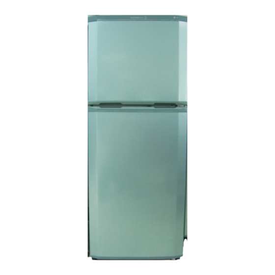
Summary of Contents for LG GN-U192SL
- Page 1 REFRIGERATOR SERVICE MANUAL CAUTION BEFORE SERVICING THE UNIT, READ THE "SAFETY PRECAUTIONS" IN THIS MANUAL. MODEL : GN-U192SL/SLK/SVK GN-U212SK/SL/SLK/SV GN-U222/U232SK/SL/SLK/SV...
-
Page 2: Table Of Contents
CONTENTS SAFETY PRECAUTIONS..............................SERVICING PRECAUTIONS..............................SPECIFICATIONS................................PARTS IDENTIFICATION..............................DISASSEMBLY.................................. 7-8 DOOR..................................... DOOR SWITCH..................................7 THERMOSTAT..................................FAN AND FAN MOTOR................................DEF' CONTROL ASM................................8 REFRIGERATOR ROOM LAMP............................. CONTROL BOX-R.................................. DISPENSER................................... ADJUSTMENT...................................9-10 COMPRESSOR..................................9 PTC-STARTER..................................9 OLP (OVER LOAD PROTECTOR)............................10... -
Page 3: Servicing Precautions
SERVICING PRECAUTIONS AIR RECHARGING IN COMPRESSOR vacuum operation is over, add the quantity in grams of R-134ato the refrigeration system. Remember that every Test the refrigeration system connecting it electrically before system has an exact quantity of R-134awith a tolerance of refilling operation. -
Page 4: Specifications
1. SPECIFICATIONS 1-1 GN-U192 ITEMS SPECIFICATIONS ITEMS SPECIFICATIONS FREEZER FREEZER 1 EA SHELF 1 EA NET CAPACITY REFRIGERATOR REFRIGERATOR ( l) Drawer Type TOTAL VEGETABLE TRAY DIMENSIONS (mm) 535(W) 585(D) 1260(H) EGG TRAY 1 EA NET WEIGHT (kg) TWIST ICE TRAY(*) TWIST ICE TRAY & ICE BANK ICE MAKER COOLING SYSTEM a F n Cooling... - Page 5 1-3 GN-U222/GN-U232 ITEMS SPECIFICATIONS ITEMS SPECIFICATIONS FREEZER FREEZER 1 EA SHELF 2 EA NET CAPACITY REFRIGERATOR REFRIGERATOR ( l) TOTAL VEGETABLE TRAY Drawer Type DIMENSIONS (mm) 535(W) 580(D) 1475(H) DEODORIZER NET WEIGHT (kg) TWIST ICE TRAY(*) TWIST ICE TRAY & ICE BANK ICE MAKER COOLING SYSTEM a F n Cooling...
-
Page 6: Parts Identification
2. PARTS IDENTIFICATION FREEZER COMPARTMENT Twisting Ice Serve Freezer Temperature Freezer Door Rack Control Dial Freezer Shelf General Type Ice Tray REFRIGERATOR COMPARTMENT Egg Storage Rack Chilled Compartment Refrigerator Temperature Movable Rack Control Knob Lamp Cover Pump Shelves Water Tank Deodorizer Vegetable Drawer Refrigerator Door... -
Page 7: Disassembly
3. DISASSEMBLY 3-1 DOOR 3-2 DOOR SWITCH Freezer Door 1. To remove the door switch, pull out it with a ‘_’ type Separating the Hinge Upper. driver as shown in (figure 9). Open the freezer door and remove the Hinge Upper (2) 2. -
Page 8: Def' Control Asm
3-6 REFRIGERATOR ROOM LAMP 5. Disconnect the housing of lead wire. 6. Separate the Fan Assy. 1. Remove the cover lamp-R by pulling with a ' _ ' type 7. Loose 2 screw fixed to the Bracket. driver. 8. Pull out Shroud-F remove the Fan Motor Assy. 2. -
Page 9: Adjustment
4. ADJUSTMENT 4-1 COMPRESSOR 4-2-3 PTC-Applied Circuit Diagram According to Starting Method of Motor 4-1-1 Role The compressor inhales low temperature and low pressure gas evaporated from Evaporator of the Refrigerator, and OVERLOAD PROTECTOR condenses this gas to high temperature and high pressure gas, and then plays delivering role to Condenser. -
Page 10: Olp (Overload Protector)
4-3 OLP (OVERLOAD PROTECTOR) 4-3-1 Definition of OLP 4-3-2 Role of the OLP (1) OLP (OVERLOAD PROTECTOR) is attached to the (1) The OLP is attached to the Hermetic Compressor used Compressor and protects the Motor by cutting the for the Refrigerator and Show Case and prevents the current to the Motor if the temperature rises and Motor Coil from being started in the Compressor. -
Page 11: Circuit Diagram
5. CIRCUIT DIAGRAM Non Dispenser Model Dispenser Model DEF TIMER THERMOSTAT BN / YL POWER SUPPLY CORD GN / YL THERMO DOOR MOTOR S/W-R LAMP-R THERMAL FUSE P .T.C COMPRESSOR STARTER THE PLUG TYPE,COMPRESSOR EARTH PART ON CIRCUIT DIAGRAM ARE SUBJECTED TO CHANGE IN DIFFERENT LOCALITIES. YL :YELLOW BL :BLUE PR :PURPLE... -
Page 12: Troubleshooting
6. TROUBLESHOOTING 6-1 COMPRESSOR AND ELECTRIC COMPONENTS (Rating Voltage Remove the PTC-Starter Power Source. + 10 % ) from the Compressor and measure the voltage between Terminal C of Compressor and Terminals 5 or 6 of PTC. No Voltage. OLP disconnected? Replace OLP. -
Page 14: Defrost Timer
6-4 ANOTHER ELECTRIC COMPONENTS Cooling is impossible Compressor Check if current flows to Cause doesn't run. the following components. Poor contacting and a. Thermostat gas leakage. b. Starting devices Shorted or broken. Poor contacting c. OLP or shorted. d. Compressor coil Coil shorted. -
Page 15: Service Diagnosis Chart
6-5 SERVICE DIAGNOSIS CHART COMPLAINT POINTS TO BE CHECKED REMEDY Cooling is Is the power cord unplugged from the outlet? Plug to the outlet. impossible. Check if the power S/W is setted to OFF. Set the switch to ON. Check if the fuse of power S/W is shorted. Replace a regular fuse. -
Page 16: Refrigerating Cycle
6-6 REFRIGERATING CYCLE Troubleshooting Chart TEMPERATURE STATE OF STATE OF THE CAUSE REMARKS OF THE THE SET EVAPORATOR COMPRESSOR PARTIAL Freezer and Low flowing sound of A little high A little Refrigerant ¥ LEAKAGE Refrigerator Refrigerant is heard and more than discharges. - Page 17 General Control of Refrigerating Cycle ITEMS UNIT STANDARDS PURPOSES REMARKS Pipe and Min. Pipe: within 1 hour. To protect The opening time should be reduced piping system Comp: within 10 minutes. moisture to a half of the standards during rain opening time Drier: within 20 minutes.
-
Page 18: Exploded View
7. EXPLODED VIEW 7-1 CASE SET ASM (GN-U192,GN-U212,GN-U222/GN-U232) NOTE: 1. The parts of refrigerator and the shape of each part are subject to change in different localities. : optional parts 301A - Twist Ice Tray : 110B, 125A, 125H, 131A 303A - General Ice Tray : 125A, 131A - Dispenser Set Asm : 611A,611M,611N,611P-T... - Page 19 7-2 DOOR SET ASM (GN-U192,GN-U212,GN-U222/GN-U232) : optional parts 405C 405A 329A 330B 200A 404A 203A 201A 212G 332A 205A 110B 125A 125A 125H 210A 131A 131A 149A 149B 230A 241F 233A 140A 231A 149C 281D 605A 149C 241B 154A 241C 151A 241D - 19 -...
- Page 20 P/No. 3828JP8007D...


Need help?
Do you have a question about the GN-U192SL and is the answer not in the manual?
Questions and answers