Table of Contents
Advertisement
Advertisement
Table of Contents

Related Manuals for FUNAI LCD-A2006


Summary of Contents for FUNAI LCD-A2006
-
Page 1: Service Manual
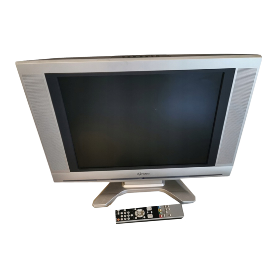
SERVICE MANUAL 20" COLOR LCD TELEVISION LCD-A2006/LCD-B2006/ LCD-C2006/LCD-D2006... -
Page 2: Table Of Contents
20″ COLOR LCD TELEVISION LCD-A2006/LCD-B2006/ LCD-C2006/LCD-D2006 TABLE OF CONTENTS Specifications ................1-1 Important Safety Precautions. -
Page 3: Specifications
SPECIFICATIONS <TUNER> ANT. Input ------------------- 80 dBµV, Video: PAL 87.5%, Audio: 30 kHz dev (1 kHz Sin) Test Input Signal----------- 400Hz 30% modulation Description Condition Unit Nominal Limit 1. Intermediate Freq. Picture PAL-BG/I/DK, SECAM-L 38.9 SECAM-L’ 33.9 Sound PAL-BG 33.4 PAL-I 32.9 PAL-DK, SECAM-L... -
Page 4: Important Safety Precautions
IMPORTANT SAFETY PRECAUTIONS Prior to shipment from the factory, our products are strictly inspected for recognized product safety and electrical codes of the countries in which they are to be sold. However, in order to maintain such compliance, it is equally important to implement the following precautions when a set is being serviced. - Page 5 4. Hot Chassis Warning - 7. Product Safety Notice - Some electrical and mechanical parts have special safety-related a. Some TV receiver chassis are electrically characteristics which are often not evident from connected directly to one conductor of the AC visual inspection, nor can the protection they give power cord and maybe safety-serviced without necessarily be obtained by replacing them with...
- Page 6 Precautions during Servicing A. Parts identified by the ! symbol are critical for M. When installing parts or assembling the cabinet safety. parts, be sure to use the proper screws and Replace only with part number specified. tighten certainly. B. In addition to safety, other parts and assemblies are specified for conformance with regulations applying to spurious radiation.
- Page 7 Safety Check after Servicing Examine the area surrounding the repaired location Chassis or Secondary Conductor for damage or deterioration. Observe that screws, parts and wires have been returned to original posi- tions. Afterwards, perform the following tests and con- Primary Circuit firm the specified values in order to verify compliance with safety standards.
-
Page 8: Standard Notes For Servicing
STANDARD NOTES FOR SERVICING Circuit Board Indications How to Remove / Install Flat Pack-IC 1. The output pin of the 3 pin Regulator ICs is 1. Removal indicated as shown. With Hot-Air Flat Pack-IC Desoldering Machine: 1. Prepare the hot-air flat pack-IC desoldering Top View Bottom View machine, then apply hot air to the Flat Pack-IC... - Page 9 With Soldering Iron: With Iron Wire: 1. Using desoldering braid, remove the solder from 1. Using desoldering braid, remove the solder from all pins of the flat pack-IC. When you use solder all pins of the flat pack-IC. When you use solder flux which is applied to all pins of the flat pack-IC, flux which is applied to all pins of the flat pack-IC, you can remove it easily.
- Page 10 2. Installation Instructions for Handling Semi- 1. Using desoldering braid, remove the solder from conductors the foil of each pin of the flat pack-IC on the CBA Electrostatic breakdown of the semi-conductors may so you can install a replacement flat pack-IC more occur due to a potential difference caused by easily.
-
Page 11: Cabinet Disassembly Instructions
CABINET DISASSEMBLY INSTRUCTIONS 1. Disassembly Flowchart Removal Step/ This flowchart indicates the disassembly steps for the Remove/*Unhook/ Loc. Part Fig. Unlock/Release/ cabinet parts, and the CBA in order to gain access to Note Unplug/Unclamp/ item(s) to be serviced. When reassembling, follow the Desolder steps in reverse order. - Page 12 [2] Rear Cabinet [1] Tilt Stand Assembly Fig. D1 [11] Front Cabinet S-10 [8] Function CBA [9] Speaker S-10 S-10 S-11 Speaker Holders [10] IR Sensor S-12 [9] Speaker S-11 [4] Inverter Speaker Holders [7] LCD Main CBA Unit & Liquid Crystal Panel Unit [6] Tilt Stand Holder [5] Main CBA...
- Page 13 [12] Stand Cover [13] Arm Holder S-14 [15] Arm Assembly [14] Sheet R S-13 S-13 [14] Sheet L Fig. D3 L4620DC...
- Page 14 TV Cable Wiring Diagram Function CBA CN31B To Liquid Crystal Panel Unit LCD Main CBA Unit CN106 CN311 CN312 Main CBA Inverter CBA CN103B CN102B CN101B CN301 CN404 CN304 CN103A CN101A CN102A To Liquid CN302 Crystal Panel Unit CN303 CN53 CN801 CN310 IR Sensor CBA...
-
Page 15: How To Initialize The Lcd Television
HOW TO INITIALIZE THE LCD TELEVISION To put the program back at the factory-default, initialize the LCD television as the following procedure. How to initialize the LCD television: 1. Turn the power on. (Use main power on the TV unit.) 2. -
Page 16: Electrical Adjustment Instructions
ELECTRICAL ADJUSTMENT INSTRUCTIONS General Note: 1. Initial Setting “CBA” is abbreviation for “Circuit Board Assem- General bly.” Enter the Service mode. NOTE: Electrical adjustments are required after replacing Set the each initial data as shown on table 1 below. circuit components and certain mechanical parts. It is Table 1: Initial Data important to perform these adjustments only after all repairs and replacements have been completed. -
Page 17: Flicker Adjustment
VOL. p → 9 C-SBB(C/D/S-2) LAST POWER FLASH (Go and Off) SYSTEM VOL. p 4. Press [CH. o / p] buttons on the remote control ASPECT unit so that flash stops. RUSSIAN *1 PAL-BG (LCD-A2006), PAL-I (LCD-B2006), SECAM-L (LCD-C2006), PAL-BG/DK (LCD-D2006) L4620EA... -
Page 18: White Balance Adjustment
The following adjustment normally are not 6. [AV1(RGB)]----(APL 80%) Press “6” button to select “C-DB(C/D/S-2)” for Blue attempted in the field. Only when replacing the adjustment. Press “4” button to select “C-DR(C/D/ LCD Panel then adjust as a preparation. S-2)” for Red adjustment.When “x” value and “y” value are not within specification, adjust “C-DB(C/ 3. -
Page 19: Block Diagrams
BLOCK DIAGRAMS System Control Block Diagram L4620BLS... - Page 20 IF/Video Block Diagram L4620BLIF...
- Page 21 Audio Block Diagram L4620BLA...
- Page 22 LCD Block Diagram L4620BLLCD...
- Page 23 Power Supply Block Diagram L4620BLP...
- Page 24 LCD Backlight Block Diagram L4620BLLB...
-
Page 25: Schematic Diagrams / Cba's And Test Points
SCHEMATIC DIAGRAMS / CBA'S AND TEST POINTS Standard Notes Many electrical and mechanical parts in this chassis have special characteristics. These characteristics often pass unnoticed and the protection afforded by them cannot necessarily be obtained by using replacement components rated for higher voltage, wattage, etc. Replacement parts that have these special safety characteristics are identified in this manual and its supplements;... - Page 26 LIST OF CAUTION, NOTES, AND SYMBOLS USED IN THE SCHEMATIC DIAGRAMS ON THE FOLLOWING PAGES: 1. CAUTION: FOR CONTINUED PROTECTION AGAINST FIRE HAZARD, REPLACE ONLY WITH THE SAME TYPE FUSE. 2. CAUTION: Fixed Voltage (or Auto voltage selectable) power supply circuit is used in this unit. If Main Fuse (F601) is blown, first check to see that all components in the power supply circuit are not defective before you connect the AC plug to the AC power supply.
- Page 27 Main 1/4 Schematic Diagram L4620SCM1...
- Page 28 Main 2/4 Schematic Diagram VOLTAGE CHART CN103A Pin No. Voltage L4620SCM2...
- Page 29 Main 3/4 Schematic Diagram CAUTION ! NOTE: CAUTION ! For continued protection against fire hazard, The voltage for parts in hot circuit is measured using Fixed voltage (or Auto voltage selectable) power supply circuit is used in this unit. replace only with the same type fuse. hot GND as a common terminal.
- Page 30 Main 4/4 & IR Sensor Schematic Diagram VOLTAGE CHART CN102A Pin No. Voltage L4620SCM4...
- Page 31 Function Schematic Diagram L4620SCF...
- Page 32 Inverter Schematic Diagram L4620SCINV...
- Page 33 LCD Main 1/2 Schematic Diagram L4620SCL1...
- Page 34 LCD Main 2/2 Schematic Diagram 8-10 L4620SCL2...
- Page 35 Main CBA Top View CAUTION ! CAUTION ! Because a hot chassis ground is present in the power supply circut, an isolation transformer must be used. For continued protection against fire hazard, Fixed voltage (or Auto voltage selectable) power supply circuit is used in this unit. If Main Fuse (F601) is blown , check to see that all components in the power supply Also, in order to have the ability to increase the input replace only with the same type fuse.
- Page 36 Main CBA Bottom View CAUTION ! CAUTION ! Because a hot chassis ground is present in the power Fixed voltage (or Auto voltage selectable) power supply circuit is used in this unit. supply circut, an isolation transformer must be used. For continued protection against fire hazard, replace only with the same type fuse.
- Page 37 Function CBA Top View IR Sensor CBA Top & Bottom View BL4520F01011-3 Function CBA Bottom View BL4520F01011-2 8-13...
- Page 38 Inverter CBA Top View Inverter CBA Bottom View 8-14 BL2500F01021...
-
Page 39: Waveforms
WAVEFORMS WF1 ~ WF8 = Waveforms to be observed at Waveform check points. (Shown in Schematic Diagram.) Input: PAL Color Bar Signal (with 1kHz Audio Signal) Pin 14 of IC801 Pin 9 of CN103A Pin 3 of CN103A AUDIO 0.1V 0.5ms CVBS2 0.2V... - Page 40 WF9 ~ WF14 = Waveforms to be observed at Waveform check points. (Shown in Schematic Diagram.) Input: PAL Color Bar Signal (with 1kHz Audio Signal) R904 R997 WF12 10µs CTKH 20ns R907 R902 WF10 WF13 STH1 1µs STV1 R901 R905 WF11 WF14 20µs...
-
Page 41: Wiring Diagram
WIRING DIAGRAMS 10-1 L4620WI... -
Page 42: Exploded View
See Electrical Parts List A9-2 for parts with this mark. A9-3 A9-6 A9-5 Main CBA A9-5 Comparison Chart of A9-7 A9-4 [ B ] Models and Marks AC601 Model Mark AC601 LCD-A2006 [ A, C, D ] LCD-B2006 LCD-C2006 LCD-D2006 11-1 L4620CEX... - Page 43 X2-8, X2-9, Models and Marks X2-5, X2-6, X2-2, X2-3, X2-10, X2-11, Model Mark X2-7, X2-12 X2-1 X2-4 X2-16, X2-17 LCD-A2006 X5 X3 LCD-B2006 LCD-C2006 LCD-D2006 Packing Tape Tape Packing Tape Packing Tape Packing Tape Some Ref. Numbers are not in sequence.
-
Page 44: Mechanical Parts List
SCREW P-TIGHT 3X10 BIND HEAD+ GBHP3100 Comparison Chart of Models and Marks SCREW S-TIGHT M3X8 BIND HEAD+ GBHS3080 Model Mark SCREW S-TIGHT M3X8 BIND HEAD+ GBJS3080 LCD-A2006 SCREW P-TIGHT 3X14 WASHER GCJP3140 HEAD+ LCD-B2006 SCREW P-TIGHT M4X18 BIND HEAD+ GBHP4180 LCD-C2006 PACKING... -
Page 45: Electrical Parts List
Comparison Chart of Models and Marks C517 ELECTROLYTIC CAP . 100µF/16V M H7 or CE1CMAVSL101 Model Mark ALUMINUM ELECTROLYTIC CAP 100µF/16V H7 CE1CMAVSM101 LCD-A2006 C527 ELECTROLYTIC CAP . 10µF/50V M H7 or CE1JMAVSL100 LCD-B2006 ALUMINUM ELECTROLYTIC CAP 10µF/50V H7 CE1JMAVSM100... - Page 46 Ref. No. Description Part No. Ref. No. Description Part No. ELECTROLYTIC CAP . 470µF/16V M CE1CMASTM471 ALUMINUM ELECTROLYTIC CAP 47µF/16V M CE1CMASTM470 C641! SAFETY CAP . 2200pF/250V KX CA2E222MR050 C743 CHIP CERAMIC CAP . F Z 2.2µF/10V CHD1AZ30F225 C643 CHIP CERAMIC CAP .(1608) B K 0.22µF/25V CHD1EK30B224 C745 ELECTROLYTIC CAP .
- Page 47 Ref. No. Description Part No. Ref. No. Description Part No. CHIP CERAMIC CAP . CJ C 3pF/50V CHD1JC3CJ3R0 SWITCHING DIODE KDS160E-RTK/P ND1ZKDS160EP C837 CHIP CERAMIC CAP . CH D 3pF/50V or CHD1JD3CH3R0 D502 ZENER DIODE MTZJT-7724B or QDTB00MTZJ24 CHIP CERAMIC CAP . CH C 3pF/50V or CHD1JC3CH3R0 ZENER DIODE DZ-24BSBT265 NDTB00DZ24BS...
- Page 48 Ref. No. Description Part No. Ref. No. Description Part No. SWITCHING DIODE KDS160E-RTK/P ND1ZKDS160EP IC SWITCHING CD4052BNSR NSZBA0TTY091 D649! ZENER DIODE MTZJT-7739B or QDTB00MTZJ39 COILS ZENER DIODE DZ-39BSBT265 NDTB00DZ39BS PCB JUMPER D0.6-P5.0 JW5.0T D650 SWITCHING DIODE 1SS400 or QD1Z001SS400 INDUCTOR 22µH-K-5FT LLARKBSTU220 SWITCHING DIODE KDS160E-RTK/P ND1ZKDS160EP...
- Page 49 Ref. No. Description Part No. Ref. No. Description Part No. CARBON RES. 1/4W J 150 Ω Q734 RES. BUILT-IN TRANSISTOR KRA103M-AT/P or NQSZ0KRA103M R519 RCX4JATZ0151 CHIP RES. 1/10W J 56k Ω or RES. BUILT-IN TRANSISTOR BN1F4M-T QQSZ00BN1F4M R520 RRXAJR5Z0563 RES CHIP 1608 1/10W J 56k Ω Q741 TRANSISTOR 2SC4081 T106 Q QQ1Q02SC4081...
- Page 50 Ref. No. Description Part No. Ref. No. Description Part No. CARBON RES. 1/4W J 10k Ω RES CHIP 1608 1/10W J 47k Ω R655 RCX4JATZ0103 RRXA473YF002 CHIP RES. 1/10W J 100k Ω or CARBON RES. 1/4W J 560 Ω R656 RRXAJR5Z0104 R741 RCX4JATZ0561...
- Page 51 Ref. No. Description Part No. Ref. No. Description Part No. CARBON RES. 1/4W J 470 Ω or RES CHIP 1608 1/10W J 22k Ω R797 RCX4JATZ0471 RRXA223YF002 CARBON RES. 1/4W J 470 Ω CHIP RES. 1/10W J 22k Ω or RCX4JATZ0471 R886 RRXAJR5Z0223...
- Page 52 FUNCTION CBA INVERTER CBA Ref. No. Description Part No. Ref. No. Description Part No. FUNCTION CBA ---------- INVERTER CBA 1ESA13345 Consists of the following: Consists of the following: CAPACITOR CAPACITORS CERAMIC CAP .(AX) F Z 0.01µF/25V CCA1EZTFZ103 C301 ELECTROLYTIC CAP . 47µF/16V M or CE1CMASDL470 CONNECTOR ELECTROLYTIC CAP .
- Page 53 Ref. No. Description Part No. Ref. No. Description Part No. CN304 CONNECTOR PRINT MES C/15/S/127301115K2 JCTWA15TG004 TRANSISTOR 2SA1318(U)-AANP 2SA1318UZ CN310 CONNECTOR PRINT OSU 008283021200000S+ J383C02UG004 Q306 TRANSISTOR 2SC2120-O(TE2 F T) or QQS02SC2120F TRANSISTOR 2SC2120-Y(TE2 F T) QQSY2SC2120F CONNECTOR PRINT OSU 2P 292161-2 J31FC02AP001 Q321! FET MOS SMD HAT2215R01-EL-E...
- Page 54 Ref. No. Description Part No. Ref. No. Description Part No. RES CHIP 1608 1/10W J 390 Ω CHIP RES. 1/10W J 1k Ω or RRXA391YF002 R363 RRXAJR5Z0102 CHIP RES. 1/10W J 390 Ω or RES CHIP 1608 1/10W J 1.0k Ω R322 RRXAJR5Z0391 RRXA102YF002...
- Page 55 LCD-A2006/LCD-B2006/LCD-C2006/LCD-D2006 L4620EA/21BB/22FC/23RD 2006-07-24...
Need help?
Do you have a question about the LCD-A2006 and is the answer not in the manual?
Questions and answers