Table of Contents
Advertisement
Quick Links
Advertisement
Table of Contents

Related Manuals for FUNAI LCD-A2006


Summary of Contents for FUNAI LCD-A2006
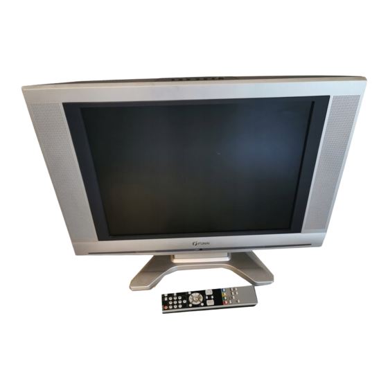
- Page 1 SERVICE MANUAL 20" COLOR LCD TELEVISION LCD-A2006/LCD-B2006/ LCD-C2006/LCD-D2006...
- Page 2 TV Cable Wiring Diagram Function CBA CN31B To Liquid Crystal Panel Unit LCD Main CBA Unit CN106 CN311 CN312 Main CBA Inverter CBA CN103B CN102B CN101B CN301 CN404 CN304 CN103A CN101A CN102A To Liquid CN302 Crystal Panel Unit CN303 CN53 CN801 CN310 IR Sensor CBA...
-
Page 3: Block Diagrams
BLOCK DIAGRAMS System Control Block Diagram L4620BLS... - Page 4 IF/Video Block Diagram L4620BLIF...
-
Page 5: Audio Block Diagram
Audio Block Diagram L4620BLA... -
Page 6: Lcd Block Diagram
LCD Block Diagram L4620BLLCD... -
Page 7: Power Supply Block Diagram
Power Supply Block Diagram L4620BLP... - Page 8 LCD Backlight Block Diagram L4620BLLB...
- Page 9 Main 1/4 Schematic Diagram L4620SCM1...
- Page 10 Main 2/4 Schematic Diagram VOLTAGE CHART CN103A Pin No. Voltage L4620SCM2...
- Page 11 Main 3/4 Schematic Diagram CAUTION ! NOTE: CAUTION ! For continued protection against fire hazard, The voltage for parts in hot circuit is measured using Fixed voltage (or Auto voltage selectable) power supply circuit is used in this unit. replace only with the same type fuse. hot GND as a common terminal.
- Page 12 Main 4/4 & IR Sensor Schematic Diagram VOLTAGE CHART CN102A Pin No. Voltage L4620SCM4...
- Page 13 Function Schematic Diagram L4620SCF...
- Page 14 Inverter Schematic Diagram L4620SCINV...
- Page 15 LCD Main 1/2 Schematic Diagram L4620SCL1...
- Page 16 LCD Main 2/2 Schematic Diagram 8-10 L4620SCL2...
- Page 17 Main CBA Top View CAUTION ! CAUTION ! Because a hot chassis ground is present in the power supply circut, an isolation transformer must be used. For continued protection against fire hazard, Fixed voltage (or Auto voltage selectable) power supply circuit is used in this unit. If Main Fuse (F601) is blown , check to see that all components in the power supply Also, in order to have the ability to increase the input replace only with the same type fuse.
- Page 18 Main CBA Bottom View CAUTION ! CAUTION ! Because a hot chassis ground is present in the power Fixed voltage (or Auto voltage selectable) power supply circuit is used in this unit. supply circut, an isolation transformer must be used. For continued protection against fire hazard, replace only with the same type fuse.
- Page 19 Function CBA Top View IR Sensor CBA Top & Bottom View BL4520F01011-3 Function CBA Bottom View BL4520F01011-2 8-13...
- Page 20 Inverter CBA Top View Inverter CBA Bottom View 8-14 BL2500F01021...
-
Page 21: Wiring Diagrams
WIRING DIAGRAMS 10-1 L4620WI...
Need help?
Do you have a question about the LCD-A2006 and is the answer not in the manual?
Questions and answers