Table of Contents
Advertisement
Advertisement
Table of Contents

Subscribe to Our Youtube Channel
Related Manuals for Asus H971-PLUS


Summary of Contents for Asus H971-PLUS
- Page 1 H97I-PLUS...
- Page 2 Product warranty or service will not be extended if: (1) the product is repaired, modified or altered, unless such repair, modification of alteration is authorized in writing by ASUS; or (2) the serial number of the product is defaced or missing.
-
Page 3: Table Of Contents
My Favorites ....................2-15 Main menu ....................2-17 Ai Tweaker menu ..................2-19 Advanced menu ..................2-29 Monitor menu ..................... 2-38 Boot menu ....................2-41 Tool menu ....................2-47 2.10 Exit menu ....................2-48 Appendices Notices ........................A-1 ASUS contact information ..................A-3... -
Page 4: Safety Information
Safety information Electrical safety • To prevent electrical shock hazard, disconnect the power cable from the electrical outlet before relocating the system. • When adding or removing devices to or from the system, ensure that the power cables for the devices are unplugged before the signal cables are connected. If possible, disconnect all power cables from the existing system before you add a device. -
Page 5: Conventions Used In This Guide
Refer to the following sources for additional information and for product and software updates. ASUS websites The ASUS website provides updated information on ASUS hardware and software products. Refer to the ASUS contact information. Optional documentation Your product package may include optional documentation, such as warranty flyers, that may have been added by your dealer. -
Page 6: Package Contents
* Hyper DIMM support is subject to the physical characteristics of individual CPUs. Please refer to Memory QVL (Qualified Vendors List) for details. ** Refer to www.asus.com for the Memory QVL (Qualified Vendors List). Expansion slots 1 x PCI Express 3.0 x16 slot... - Page 7 ASUS High-Quality Solid Capacitors - 2.5x Longer lifespan with excellent durability ASUS Stainless Steel Back I/O - 3x More durable corrosion-resistant coating Gaming Scenario ASUS audio features: Feel the sound power with different usage scenarios Steam OS Support (continued on the next page)
- Page 8 - AI Suite 3 - Anti Surge - MemOK! ASUS Quiet Thermal Solution - ASUS Fan Xpert 2+ featuring Fan Auto Tuning function for optimized speed control ASUS EZ DIY - Push Notice - Monitor your PC status with smart devices in real time...
- Page 9 64 Mb Flash ROM, UEFI AMI BIOS, PnP, DMI 2.0, WfM 2.0, SM BIOS BIOS features 2.8, ACPI 2.0a, Multi-language BIOS, ASUS EZ Flash 2, ASUS CrashFree BIOS 3, My Favorites, Quick Note, Last Modified Log, F12 PrintScreen function, F3 Shortcut functions, and ASUS DRAM SPD (Serial Presence...
-
Page 11: Chapter 1: Product Introduction
• Unplug the power cord from the wall socket before touching any component. • Before handling components, use a grounded wrist strap or touch a safely grounded object or a metal object, such as the power supply case, to avoid damaging them due to static electricity. • Hold components by the edges to avoid touching the ICs on them. • Whenever you uninstall any component, place it on a grounded antistatic pad or in the bag that came with the component. • Before you install or remove any component, ensure that the ATX power supply is switched off or the power cord is detached from the power supply. Failure to do so may cause severe damage to the motherboard, peripherals, or components. ASUS H97I-PLUS... -
Page 12: Motherboard Overview
Motherboard overview Before you install the motherboard, study the configuration of your chassis to ensure that the motherboard fits. Unplug the power cord before installing or removing the motherboard. Failure to do so can cause you physical injury and damage to motherboard components. 1.2.1 Placement direction When installing the motherboard, place it into the chassis in the correct orientation. The edge with external ports goes to the rear part of the chassis as indicated in the image. 1.2.2 Screw holes Place six screws into the holes indicated by circles to secure the motherboard to the chassis. Do not overtighten the screws! Doing so can damage the motherboard. -
Page 13: Motherboard Layout
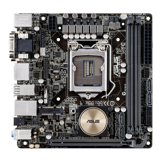
1.2.3 Motherboard layout 17cm(6.7in) KBMS_USB3_56 EATX12V CHA_FAN1 CHA_FAN2 CPU_FAN HDMI LGA1150 1442K Super USB7-10 LAN_USB3_34 MemOK! DRAM_LED Mini PCIe Intel AAFP ® SPDIFO 64Mb BIOS Intel I218V AUDIO CLRTC USB1112 PCIEX16 SPDIF_OUT ASUS H97I-PLUS... -
Page 14: Central Processing Unit (Cpu)
1.2.4 Layout contents Connectors/Headers/Slots/LEDs Page 1. CPU and chassis fan connectors (4-pin CPU_FAN, 4-pin CHA_FAN1/2) 1-16 2. ATX power connectors (24-pin EATXPWR, 8-pin EATX12V) 1-18 3. TPM header (20-1 pin TPM) 1-18 4. MemOK! button 1-20 5. LGA1150 CPU socket 6. DRAM LED (DRAM_LED) 1-21 7. DDR3 DIMM slots 8. Standby power LED (SB_PWR) 1-21 9. Speaker connector (4-pin SPEAKER) 1-16 10. System panel connector (10-1 pin F_PANEL) 1-19 11. Intel H97 Serial ATA 6.0 Gb/s connectors (7-pin SATA6G_1-4) 1-14 ® 12. USB 3.0 connector (20-1 pin USB3_12) 1-15 13. M.2 Socket 3 1-17... -
Page 15: Installing The Cpu
• Upon purchase of the motherboard, ensure that the PnP cap is on the socket and the socket contacts are not bent. Contact your retailer immediately if the PnP cap is missing, or if you see any damage to the PnP cap/socket contacts/motherboard components. ASUS will shoulder the cost of repair only if the damage is shipment/ transit-related. • Keep the cap after installing the motherboard. ASUS will process Return Merchandise Authorization (RMA) requests only if the motherboard comes with the cap on the LGA1150 socket. • The product warranty does not cover damage to the socket contacts resulting from incorrect CPU installation/removal, or misplacement/loss/incorrect removal of the PnP cap. 1.3.1 Installing the CPU ASUS H97I-PLUS... -
Page 16: Cpu Heatsink And Fan Assembly Installation
1.3.2 CPU heatsink and fan assembly installation Apply the Thermal Interface Material to the CPU heatsink and CPU before you install the heatsink and fan if necessary. Chapter 1: Product introduction... - Page 17 To install the CPU heatsink and fan assembly To uninstall the CPU heatsink and fan assembly ASUS H97I-PLUS...
-
Page 18: System Memory
OS. ® I nstall a 64-bit Windows OS if you want to install 4GB or more on the ® motherboard. F or more details, refer to the Microsoft support site at http://support.microsoft. ® com/kb/929605/en-us. • This motherboard does not support DIMMs made up of 512 megabits (Mb) chips or less. • The default memory operation frequency is dependent on its Serial Presence Detect (SPD), which is the standard way of accessing information from a memory module. Under the default state, some memory modules for overclocking may operate at a lower frequency than the vendor-marked value. To operate at the vendor-marked or at a higher frequency, refer to section 2.5 Ai Tweaker menu for manual memory frequency adjustment. • For system stability, use a more efficient memory cooling system to support a full memory load or overclocking condition. • Visit the ASUS website at: www.asus.com for the latest QVL. Chapter 1: Product introduction... - Page 19 1.4.3 Installing a DIMM To remove a DIMM ASUS H97I-PLUS...
-
Page 20: Expansion Slots
Expansion slots In the future, you may need to install expansion cards. The following sub-sections describe the slots and the expansion cards that they support. Unplug the power cord before adding or removing expansion cards. Failure to do so may cause you physical injury and damage motherboard components. 1.5.1 Installing an expansion card To install an expansion card: Before installing the expansion card, read the documentation that came with it and make the necessary hardware settings for the card. Remove the system unit cover (if your motherboard is already installed in a chassis). -
Page 21: Headers
Clear CMOS Values (Open) (Short) H97I-PLUS Clear RTC RAM To erase the RTC RAM: Turn OFF the computer and unplug the power cord. Use a metal object such as a screwdriver to short the two pins. Plug the power cord and turn ON the computer. Hold down the <Del> key during the boot process and enter BIOS setup to re- enter data. • If the steps above do not help, remove the onboard battery and short the two pins again to clear the CMOS RTC RAM data. After clearing the CMOS, reinstall the battery. • You do not need to clear the RTC when the system hangs due to overclocking. For system failure due to overclocking, use the CPU Parameter Recall (C.P.R.) feature. Shut down and reboot the system, then the BIOS automatically resets parameter settings to default values. ASUS H97I-PLUS 1-11... -
Page 22: Connectors
Connectors 1.7.1 Rear panel connectors PS/2 Mouse/Keyboard combo port. This port connects to a PS/2 mouse or PS/2 keyboard. Video Graphics Adapter (VGA) port. This 15-pin port is for a VGA monitor or other VGA-compatible devices. DisplayPort. This port connects a display monitor or a home-theater system. USB 2.0 ports 7 ~ 10. These 4-pin Universal Serial Bus (USB) ports are available for connecting USB 2.0/1.1 devices. LAN (RJ-45) port. These ports allow Gigabit connection to a Local Area Network (LAN) through a network hub. LAN port LED indications Activity/Link LED Speed LED Status... - Page 23 HDMI port. This port is for a High-Definition Multimedia Interface (HDMI) connector, and is HDCP compliant allowing playback of HD DVD, Blu-ray, and other protected content. DVI-D port. This port is for any DVI-D compatible device. DVI-D can’t be converted to output RGB Signal to CRT and isn’t compatible with DVI-I. • Multi-VGA output supports up to three displays under Windows OS environment, two ® displays under BIOS, and one display under DOS. • Intel display architecture design supports the following maximum supported pixel ® clocks (Pixel Clock = H total x V Total x Frame Rate (Screen refresh rate)): DVI port supports: 165 MHz DisplayPort supports: 533 MHz HDMI port supports: 300 MHz USB 3.0 ports 5 and 6. These 9-pin Universal Serial Bus (USB) ports connect to USB 3.0/2.0 devices. ASUS H97I-PLUS 1-13...
-
Page 24: Internal Connectors
1.7.2 Internal connectors Intel H97 Serial ATA 6.0 Gb/s connectors (7-pin SATA6G_1-4) ® These connectors connect to Serial ATA 6.0 Gb/s hard disk drives via Serial ATA 6.0 Gb/s signal cables. If you installed Serial ATA hard disk drives, you can create a RAID 0, 1, 5, and 10 configuration with the Intel Rapid Storage Technology through the onboard Intel H97 ® ® chipset. SATA6G_1 SATA6G_3 RSATA_TXP1 RSATA_TXP3 RSATA_TXN1 RSATA_TXN3 RSATA_RXN1 RSATA_RXN3 RSATA_RXP1 RSATA_RXP3 SATA6G_2 SATA6G_4 RSATA_TXP2 RSATA_TXP4 RSATA_TXN2 RSATA_TXN4 RSATA_RXN2 RSATA_RXN4 RSATA_RXP2 RSATA_RXP4 H97I-PLUS SATA 6.0Gb/s connectors... -
Page 25: Usb 3.0/Usb 2.0 Connector
• These USB 3.0 ports only support Turbo Mode when using USB 3.0 Boost feature. USB 2.0 connector (10-1 pin USB1112) This connector is for USB 2.0 ports. Connect the USB module cable to this connector, then install the module to a slot opening at the back of the system chassis. This USB connector complies with USB 2.0 specification that supports up to 480 Mbps connection speed. USB1112 PIN 1 H97I-PLUS USB2.0 connector Never connect a 1394 cable to the USB connector. Doing so will damage the motherboard! The USB 2.0 module is purchased separately. ASUS H97I-PLUS 1-15... - Page 26 Do not place jumper caps on the fan connectors! • Ensure that the CPU fan cable is securely installed to the CPU fan connector. • The CPU_FAN connector supports the CPU fan of maximum 1A (12 W) fan power. • The CPU_FAN and CHA_FAN connectors support the ASUS FAN Xpert 2+ feature. • The chassis fan connectors support DC and PWM modes. To set these fans to DC or PWM, go to Advanced Mode > Monitor > Chassis Fan 1/2 Q-Fan Control items in BIOS. Speaker connector (4- pin SPEAKER) This 4-pin connector is for the chassis-mounted system warning speaker. The speaker allows you to hear system beeps and warnings.
- Page 27 PIN 1 HD-audio-compliant Legacy AC’97 pin definition compliant definition H97I-PLUS Front panel audio connector • We recommend that you connect a high-definition front panel audio module to this connector to avail of the motherboard’s high-definition audio capability. • If you want to connect a high-definition or an AC’97 front panel audio module to this connector, set the Front Panel Type item in the BIOS setup to [HD Audio] or [AC97]. M.2 Socket 3 This socket allows you to install an M.2 (NGFF) SSD module. M.2(SOCKET3) H97I-PLUS M.2(SOCKET3) • This socket supports M Key and type 2260/2280 storage devices. • When using Intel Desktop Responsiveness technologies with PCIe M.2 device, ® ensure to set up the Windows UEFI operating system under RAID mode. ® The M.2 (NGFF) SSD module is purchased separately. ASUS H97I-PLUS 1-17...
- Page 28 For a fully configured system, we recommend that you use a power supply unit (PSU) that complies with ATX 12V Specification 2.0 (or later version) and provides a minimum power of 350 W. • DO NOT forget to connect the 4-pin/8-pin EATX12V power plug. Otherwise, the system will not boot. • We recommend that you use a PSU with a higher power output when configuring a system with more power-consuming devices. The system may become unstable or may not boot up if the power is inadequate. • If you want to use two high-end PCI Express x16 cards, use a PSU with 1000W power or above to ensure the system stability. • If you are uncertain about the minimum power supply requirement for your system, refer to the Recommended Power Supply Wattage Calculator at http://support.asus. com/PowerSupplyCalculator/PSCalculator.aspx?SLanguage=en-us for details. TPM connector (20-1 pin TPM) This connector supports a Trusted Platform Module (TPM) system, which securely store keys, digital certificates, passwords and data. A TPM system also helps enhance network security, protect digital identities, and ensures platform integrity. PIN 1 PCICLK FRAME PCIRST# LAD3 LAD2 LAD1 LAD0 +3VSB...
-
Page 29: System Panel Connector
This connector is for the system power button. Pressing the power switch for more than four seconds while the system is ON turns the system OFF. • Reset button (2-pin RESET) This 2-pin connector is for the chassis-mounted reset button for system reboot without turning off the system power. Mini PCIe slot This slot allows you to install a Mini PCIe module. Mini PCIe H97I-PLUS Mini PCIe slot The Mini PCIe module is purchased separately. ASUS H97I-PLUS 1-19... -
Page 30: Onboard Buttons And Switches
H97I-PLUS MemOK! button • Refer to section 1.9 Onboard LEDs for the exact location of the DRAM_LED. • The DRAM_LED also lights up when the DIMM is not properly installed. Turn off the system and reinstall the DIMM before using the MemOK! function. • The MemOK! switch does not function under Windows OS environment. ® • During the tuning process, the system loads and tests failsafe memory settings. It takes about 30 seconds for the system to test one set of failsafe settings. If the test fails, the system reboots and test the next set of failsafe settings. The blinking speed of the DRAM_LED increases, indicating different test processes. • Due to memory tuning requirement, the system automatically reboots when each timing set is tested. If the installed DIMMs still fail to boot after the whole tuning process, the DRAM_LED lights continuously. Replace the DIMMs with ones recommended in the Memory QVL (Qualified Vendors Lists) on the ASUS website at www.asus.com. • If you turn off the computer and replace DIMMs during the tuning process, the system continues memory tuning after turning on the computer. To stop memory tuning, turn off the computer and unplug the power cord for about 5–10 seconds. • If your system fails to boot up due to BIOS overclocking, press the MemOK! switch to boot and load the BIOS default settings. A message will appear during POST reminding you that the BIOS has been restored to its default settings. • We recommend that you download and update to the latest BIOS version from the ASUS website at www.asus.com after using the MemOK! function. 1-20 Chapter 1: Product introduction... -
Page 31: Onboard Leds
Onboard LEDs Standby Power LED The motherboard comes with a standby power LED that lights up to indicate that the system is ON, in sleep mode, or in soft-off mode. This is a reminder that you should shut down the system and unplug the power cable before removing or plugging in any motherboard component. The illustration below shows the location of the onboard LED. SB_PWR H97I-PLUS Onboard LED DRAM LED DRAM LED checks the DRAM in sequence during motherboard booting process. If an error is found , the LED next to the error device will continue lighting until the problem is solved. This user-friendly design provides an intuitional way to locate the root problem within a second. DRAM_LED H97I-PLUS DRAM LED ASUS H97I-PLUS 1-21... -
Page 32: Software Support
® ® (32/64bit) Operating Systems (OS). Always install the latest OS version and corresponding updates to maximize the features of your hardware. Motherboard settings and hardware options vary. Refer to your OS documentation for detailed information. 1.10.2 Support DVD information The Support DVD that comes with the motherboard package contains the drivers, software applications, and utilities that you can install to avail all motherboard features. The contents of the Support DVD are subject to change at any time without notice. Visit the ASUS website at www.asus.com for updates. To run the Support DVD Place the Support DVD into the optical drive. If Autorun is enabled in your computer, the DVD automatically displays the Specials screen which lists the unique features of your ASUS motherboard. Click Drivers, Utilities, AHCI/RAID Driver, Manual, Contact, and Specials tabs to display their respective menus. The following screen is for reference only. Click an icon to display Support DVD/motherboard information Click an item to install If Autorun is NOT enabled in your computer, browse the contents of the Support DVD to locate the file ASSETUP.EXE from the BIN folder. Double-click the ASSETUP.EXE to run... -
Page 33: Chapter 2: Bios Information
Managing and updating your BIOS Save a copy of the original motherboard BIOS file to a USB flash disk in case you need to restore the BIOS in the future. Copy the original motherboard BIOS using the ASUS Update utility. -
Page 34: Asus Ez Flash
2.1.2 ASUS EZ Flash 2 The ASUS EZ Flash 2 feature allows you to update the BIOS without using an OS‑based utility. Before you start using this utility, download the latest BIOS file from the ASUS website at www.asus.com. To update the BIOS using EZ Flash 2: Insert the USB flash disk that contains the latest BIOS file to the USB port. -
Page 35: Asus Crashfree Bios 3 Utility
2.1.3 ASUS CrashFree BIOS 3 utility The ASUS CrashFree BIOS 3 is an auto recovery tool that allows you to restore the BIOS file when it fails or gets corrupted during the updating process. You can restore a corrupted BIOS file using the motherboard support DVD or a USB flash drive that contains the updated BIOS file. - Page 36 ENTER to select boot device ESC to boot using defaults P2: ST3808110AS (76319MB) aigo miniking (250MB) UEFI: (FAT) ASUS DRW-2014L1T(4458MB) P1: ASUS DRW-2014L1T(4458MB) UEFI: (FAT) aigo miniking (250MB) Enter Setup When the booting message appears, press <Enter> within five (5) seconds to enter FreeDOS prompt.
- Page 37 DO NOT shut down or reset the system while updating the BIOS to prevent system boot failaure. Ensure to load the BIOS default settings to ensure system compatibility and stability. Select the Load Optimized Defaults item under the Exit BIOS menu. See section 2.10 Exit Menu for details. ASUS H97I-PLUS...
-
Page 38: Bios Setup Program
The BIOS setup screens shown in this section are for reference purposes only, and may not exactly match what you see on your screen. • Visit the ASUS website at www.asus.com to download the latest BIOS file for this motherboard. •... -
Page 39: Ez Mode
Click the button to manually Saves the changes Selects the boot tune the fans and resets the device priority system Loads optimized default settings The boot device options vary depending on the devices you installed to the system. ASUS H97I-PLUS 2‑7... -
Page 40: Advanced Mode
2.2.2 Advanced Mode The Advanced Mode provides advanced options for experienced end‑users to configure the BIOS settings. The figure below shows an example of the Advanced Mode. Refer to the following sections for the detailed configurations. To access the EZ Mode, click EzMode(F7) or press <F7>. Q-Fan control EZ Tuning Wizard... -
Page 41: Menu Bar
This button above the menu bar allows you to view and tweak the overclocking settings of your system. It also allows you to change the motherboard’s SATA mode from AHCI to RAID mode. Refer to section 2.2.4 EZ Tuning Wizard for more information. ASUS H97I-PLUS... -
Page 42: Hot Keys
Quick Note (F9) This button above the menu bar allows you to key in notes of the activities that you have done in BIOS. • The Quick Note function does not support the following keyboard functions: delete, cut, copy and paste. •... -
Page 43: Qfan Control
Click to activate DC Click to activate to be configured Mode PWM Mode Select a profile to apply Click to apply to your fans the fan setting Click to undo Click to the changes go back to main menu ASUS H97I-PLUS 2-11... -
Page 44: Configuring Fans Manually
Configuring fans manually Select Manual from the list of profiles to manually configure your fans’ operating speed. Click to manually Speed points configure your fans To configure your fans: Select the fan that you want to configure and to view its current status. Click and drag the speed points to adjust the fans’... -
Page 45: Ez Tuning Wizard
Select the CPU fan type (Box cooler, Tower cooler, or Water cooler) that you installed then click Next. If you are not sure of the CPU fan type, click I’m not sure. The system automatically detects the CPU fan type. Click Next then click Yes to confirm auto‑tuning. ASUS H97I-PLUS 2‑13... -
Page 46: Creating Raid
Creating RAID To create RAID: Press <F11> on your keyboard or click from the BIOS screen to open EZ Tuning Wizard screen. Click RAID then click Next. • Ensure that your HDDs have no existing RAID volumes. • Ensure to connect your HDDs to Intel SATA connectors. -
Page 47: My Favorites
My Favorites MyFavorites is your personal space where you can easily save and access your favorite BIOS items. ASUS H97I-PLUS 2-15... - Page 48 Adding items to My Favorites To add BIOS items: Press <F3> on your keyboard or click from the BIOS screen to open Setup Tree Map screen. On the Setup Tree Map screen, select the BIOS items that you want to save in MyFavorites screen.
-
Page 49: Main Menu
Administrator Password If you have set an administrator password, we recommend that you enter the administrator password for accessing the system. Otherwise, you might be able to see or change only selected fields in the BIOS setup program. ASUS H97I-PLUS 2‑17... -
Page 50: User Password
To set an administrator password: Select the Administrator Password item and press <Enter>. From the Create New Password box, key in a password, then press <Enter>. Confirm the password when prompted. To change an administrator password: Select the Administrator Password item and press <Enter>. From the Enter Current Password box, key in the current password, then press <Enter>. -
Page 51: Ai Tweaker Menu
[Auto] Sets all CPU Core Ratio to Intel CPU default settings automatically. ® [Sync All Cores] Allows you to set CPU Core Ratio settings for all cores. [Per Core] Allows you to set CPU Core Ratio individually. ASUS H97I-PLUS 2-19... -
Page 52: Gpu Boost
The following two items appear only when you set the CPU Core Ratio to [Sync All Cores] or [Per Core]. 1-Core Ratio Limit [Auto] Select [Auto] to apply the CPU default Turbo Ratio setting or manually assign a 1‑Core Limit value, which should be higher than or equal to the 2‑Core Ratio Limit. 2-Core Ratio Limit [Auto] Select [Auto] to apply the CPU default Turbo Ratio setting or manually assign a 2‑Core Ratio Limit value. -
Page 53: Dram Timing Control
2.5.8 EPU Power Saving Mode [Disabled] ASUS EPU (Energy Processing Unit) sets the CPU in its minimum power consumption settings. Enable this item to set lower CPU VCCIN and Vcore voltages and achieve the best energy saving condition. Configuration options: [Disabled] [Enabled] 2.5.9... - Page 54 The following item appears only when you set the CPU Power Phase Control to [Power Phase Response]. Power Phase Response [Fast] This item allows you to set a faster phase response for the CPU to increase system performance or to slower phase response to decrease DRAM power efficiency. Configuration options: [Ultra Fast] [Fast] [Medium] [Regular] CPU Power Duty Control [T.Probe] DIGI + VRM Duty control adjusts the current and thermal conditions of every component’s...
- Page 55 DRAM Power Phase Control [Auto] Select [Extreme] for full phase mode to increase system performance or select [Optimized] for ASUS optimized phase tuning profile to increase DRAM power efficiency. Configuration options: [Auto] [Optimized] [Extreme] 2.5.11 Internal CPU Power Management The subitems in this menu allow you to set the CPU ratio and their features.
- Page 56 CPU Internal Power Fault Control Thermal Feedback [Auto] Allows your system to take precautionary actions to protect the CPU when the thermal condition of the external regulator exceeds the threshold. Configuration options: [Auto] [Disabled] [Enabled] CPU Integrated VR Fault Management [Auto] Disable this item to prevent tripping the Fully Integrated Voltage Regulator when doing over‑voltage.
- Page 57 CPU Cache Voltage [Auto] This item allows you to set the amount of voltage fed to the CPU uncores including its cache. Increase the voltage when setting a high CPU cache frequency. Configuration options: [Auto] [Manual Mode] [Offset Mode]. ASUS H97I-PLUS 2-25...
-
Page 58: Offset Mode Sign
The following item appears only when you set the CPU Cache Voltage to [Manual Mode]. CPU Cache Voltage Override [Auto] This item allows you to set the CPU Cache Voltage override. By default, this item takes the standard value of the installed CPU. You can use the <+> or <‑> keys to adjust the value. The values range from 0.001V to 1.920V with a 0.001V interval. - Page 59 The values range from 0.001V to 0.999V with a 0.001V interval. 2.5.19 SVID Support [Auto] Set this item to [Enabled] when overclocking your system. Disabling this item stops the CPU from communicating with the external voltage regulator. Configuration options: [Auto] [Disabled] [Enabled] ASUS H97I-PLUS 2‑27...
- Page 60 The following item appears only when you set SVID Support to [Enabled]. SVID Voltage Override [Auto] This item allows you to set the SVID Voltage override. By default, this item takes the standard value of the installed CPU. You can use the <+> or <‑> keys to adjust the value. The values range from 0.001V to 2.440 V with a 0.001 V interval.
-
Page 61: Advanced Menu
2), and EMTTM (Enhanced Multi‑threaded Thermal Monitoring). Configuration options: [Disabled] [Enabled] Hyper-threading [Enabled] Allows a hyper‑threading processor to appear as two logical processors, allowing the operating system to schedule two threads or processes simultaneously. Configuration options: [Disabled] [Enabled] ASUS H97I-PLUS 2-29... -
Page 62: Cpu Power Management Configuration
Active Processor Cores [All] This item allows you to select the number of CPU cores to activate in each processor package. Configuration options: [All] [1] [2] [3] For some CPU types, only [All] and [1] appear. Limit CPUID Maximum [Disabled] When set to [Enabled], this item allows the legacy OS to boot even without support for CPUs with extended CPUID functions. -
Page 63: Pch Configuration
The system automatically wakes up and set to Rapid Start Technology S3 mode. Configuration options: [Enabled] [Disabled] Entry After [0] This item allows you to set the RTC wake‑up timer at S3 entry. The time ranges from 0 minute (immediately) to 120 minutes. ASUS H97I-PLUS 2‑31... -
Page 64: Pch Storage Configuration
Active Page Threshold Support [Enabled] The system automatically goes into sleep mode when the partition size is not enough for the Intel Rapid Start Technology to work. ® Configuration options: [Enabled] [Disabled] Active Memory Threshold [0] This item supports Intel Rapid Storage Technology when the partition size is greater than the Active Page Threshold size. -
Page 65: System Agent Configuration
This item allows you to control various DMI (direct media interface) to run at PCI‑E 2.0 speed. DMI Gen 2 [Enabled] Set this item to [Enabled] to run DMI at PCI‑E 2.0 speed. Configuration options: [Enabled] [Disabled] ASUS H97I-PLUS 2‑33... -
Page 66: Memory Configuration
NB PCI-E Configuration Allows you to configure the NB PCI Express settings. PCI-Ex16_1 Link Speed [Auto] Allows you to configure the PCIEx16 speed for slot 1. Configuration options: [Auto] [Gen1] [Gen2] [Gen3] Memory Configuration Allows you to configure the memory configuration parameters. Memory Scrambler [Enabled] Set this item to [Enabled] to support high frequency DRAMs for a better stability. -
Page 67: Platform Misc Configuration
ASPM to take effect. Configuration options: [Disabled] [L0s] [L1] [L0sL1] PEG ASPM Support [Disabled] This item allows you to select the ASPM state for energy‑saving conditions, or use the ASUS optimized energy saving profile. Configuration options: [Disabled] [Auto] [ASPM L0s] [L1] [L0sL1] 2.6.7... - Page 68 The following three items appear only when you set the HD Audio Controller item to [Enabled]. Front Panel Type [HD] Allows you to set the front panel audio connector (AAFP) mode to legacy AC’97 or high‑definition audio depending on the audio standard that the front panel audio module supports.
-
Page 69: Network Stack Configuration
The following two items appear only when you set the previous item to [Enabled]. Ipv4 / Ipv6 PXE Support [Enabled] This item allows you to enable or disable the Ipv4/Ipv6 PXE wake event. Configuration options: [Disable Link] [Enabled] ASUS H97I-PLUS 2‑37... -
Page 70: Monitor Menu
Monitor menu The Monitor menu displays the system temperature/power status, and allows you to change the fan settings. Scroll down to display the other BIOS items. 2.7.1 Qfan Tuning Click this item to automatically detect the lowest speed and configure the minimum duty cycle for each fan. - Page 71 Chassis Fan 1/2 Q-Fan Control [DC Mode] [PWM mode] Enables the chassis Q‑Fan control in PWM mode for 4‑pin chassis fan. [DC mode] Enables the chassis Q‑Fan control in DC mode for 3‑pin chassis fan. [Disabled] Disables the chassis Q‑Fan control feature. ASUS H97I-PLUS 2‑39...
- Page 72 The following items appear only when you set the Chassis Fan 1/2 Q‑Fan Control to [PWM Mode] or [DC Mode]. Chassis Fan 1/2 Q-Fan Source [CPU] This item controls the assigned fan according to the selected temperature source. Configuration options: [CPU] [MB] Chassis Fan 1/2 Speed Low Limit [600 RPM] This item allows you to disable or set the chassis fan warning speed.
-
Page 73: Boot Menu
POST time. [Full Initialization] All USB devices will be available during POST. This process will extend the POST time. [Partial Initialization] For a faster POST time, only the USB ports with keyboard and mouse connections will be detected. ASUS H97I-PLUS 2-41... - Page 74 PS/2 Keyboard and Mouse Support [Auto] Select any of these settings when PS/2 keyboard and mouse are installed. These settings only apply when Fast Boot is enabled. [Auto] For a faster POST time, PS/2 devices will only be available when the system boots up or rebooted when the PS/2 devices have not been reconnected or changed.
- Page 75 Option ROM Messages [Enabled] [Enabled] The third‑party ROM messages will be displayed during POST. [Disabled] Disables the ROM messages and displays only the ASUS logo during POST. 2.8.6 Interrupt 19 Capture [Disabled] This item allows you to trap Interrupt 19 by the option ROMs. Configuration options: [Disabled] [Enabled] 2.8.7...
-
Page 76: Secure Boot
2.8.10 Secure Boot Allows you to configure the Windows Secure Boot settings and manage its keys to protect ® the system from unauthorized access and malwares during POST. OS Type [Windows UEFI mode] Allows you to select your installed operating system. [Windows UEFI mode] This item allows you to select your installed operating system. - Page 77 Allows you to delete the DBX file from your system. Doing so may expose the system to security threats. Load Default dbx Select Yes to load the system default dbx or select No to load a downloaded dbx from a USB storage device. ASUS H97I-PLUS 2-45...
-
Page 78: Boot Option Priorities
OS in Safe Mode, press <F8 > after POST (Windows 8 not supported). • To select the boot device during system startup, press <F8> when ASUS Logo appears. 2.8.12 Boot Override These items displays the available devices. The number of device items that appears on the screen depends on the number of devices installed in the system. -
Page 79: Tool Menu
<Enter> to display the submenu. 2.9.1 ASUS EZ Flash 2 Utility Allows you to run ASUS EZ Flash 2. Press [Enter] to launch the ASUS EZ Flash 2 screen. For more details, see section 2.1.2 ASUS EZ Flash 2. 2.9.2 Setup Animator [Enabled] Enables or disables the Setup animator. -
Page 80: Exit Menu
2.9.4 ASUS SPD Information DIMM Slot number [DIMM_A1] Displays the Serial Presence Detect (SPD) information of the DIMM module installed on the selected slot. Configuration options: [DIMM_A1] [DIMM_B1] 2.10 Exit menu The Exit menu items allow you to load the optimal default values for the BIOS items, and save or discard your changes to the BIOS items. -
Page 81: Appendices
Appendices Notices Federal Communications Commission Statement This device complies with Part 15 of the FCC Rules. Operation is subject to the following two conditions: • This device may not cause harmful interference. • This device must accept any interference received including interference that may cause undesired operation. -
Page 82: Canadian Department Of Communications Statement
ASUS Recycling/Takeback Services ASUS recycling and takeback programs come from our commitment to the highest standards for protecting our environment. We believe in providing solutions for you to be able to responsibly recycle our products, batteries, other components as well as the packaging materials. -
Page 83: Asus Contact Information
+1-510-739-3777 +1-510-608-4555 Web site http://www.asus.com/us/ Technical Support Support fax +1-812-284-0883 General support +1-812-282-2787 Online support http://www.service.asus.com/ ASUS COMPUTER GmbH (Germany and Austria) Address Harkort Str. 21-23, D-40880 Ratingen, Germany +49-2102-959931 Web site http://www.asus.com/de Online contact http://eu-rma.asus.com/sales Technical Support Telephone +49-2102-5789555... - Page 84 Appendices...
Need help?
Do you have a question about the H971-PLUS and is the answer not in the manual?
Questions and answers