Asus H97-PRO GAMER User Manual
Hide thumbs
Also See for H97-PRO GAMER:
- Manual (148 pages) ,
- Manual (48 pages) ,
- Quick start manual (2 pages)
Table of Contents
Advertisement
Advertisement
Table of Contents

Related Manuals for Asus H97-PRO GAMER


Summary of Contents for Asus H97-PRO GAMER
- Page 1 H97-PRO GAMER E9495_H97-PRO_GAMER_Guide.indb 1 2014/6/20 16:05:49...
- Page 2 Product warranty or service will not be extended if: (1) the product is repaired, modified or altered, unless such repair, modification of alteration is authorized in writing by ASUS; or (2) the serial number of the product is defaced or missing.
-
Page 3: Table Of Contents
Contents Safety information ..................iv About this guide ..................iv Package contents ..................vi H97-PRO GAMER specifications summary ..........vi Product introduction Before you proceed ..............1-1 Motherboard overview ..............1-1 Central Processing Unit (CPU) ........... 1-3 System memory ................1-7 Expansion slots ................ -
Page 4: Safety Information
Safety information Electrical safety • To prevent electrical shock hazard, disconnect the power cable from the electrical outlet before relocating the system. • When adding or removing devices to or from the system, ensure that the power cables for the devices are unplugged before the signal cables are connected. If possible, disconnect all power cables from the existing system before you add a device. -
Page 5: Conventions Used In This Guide
Refer to the following sources for additional information and for product and software updates. ASUS websites The ASUS website provides updated information on ASUS hardware and software products. Refer to the ASUS contact information. Optional documentation Your product package may include optional documentation, such as warranty flyers, that may have been added by your dealer. -
Page 6: Package Contents
** Hyper DIMM support is subject to the physical characteristics of individual CPUs. Please refer to Memory QVL (Qualified Vendors List) for details. *** Refer to www.asus.com for the latest Memory QVL (Qualified Vendors List). Integrated graphics processor - Intel HD Graphics support ®... -
Page 7: Performance Optimization
- 6 x USB 3.0 / 2.0 ports* (2 ports at mid-board, 4 ports at rear panel, blue) - 8 x USB 2.0 ports (6 ports at mid-board, 2 ports at rear panel) * with ASUS USB 3.0 Boost support Gamer’s Guardian - ESD Guards on VGA, LAN, Audio, KBMS and USB 3.0/ 2.0 ports... - Page 8 H97-PRO GAMER specifications summary Interactive HomeCloud Media Streamer - Pipe music or movies from your PC to a smart TV - Media Streamer app for portable smartphone/tablet, supporting iOS7 and Android 4.0 system Gaming Scenario Steam support - Compatible with the most fun gaming platform under Windows system...
- Page 9 1 x 8-pin EATX 12V power connector 64 Mb Flash ROM, UEFI AMI BIOS, PnP, DMI 2.7, WfM2.0, SM BIOS 2.8, ACPI 5.0, Multi-language BIOS, ASUS EZ Flash 2, ASUS CrashFree BIOS BIOS features 3, F11 EZ Tuning Wizard, F6 Qfan Control, F3 My Favorites, Quick Note,...
- Page 10 E9495_H97-PRO_GAMER_Guide.indb 10 2014/6/20 16:05:50...
-
Page 11: Product Introduction
1.2.2 Screw holes Place eight screws into the holes indicated by circles to secure the motherboard to the chassis. Do not overtighten the screws! Doing so can damage the motherboard. ASUS H97-PRO GAMER E9495_H97-PRO_GAMER_Guide.indb 1 2014/6/20 16:05:50... -
Page 12: Motherboard Layout
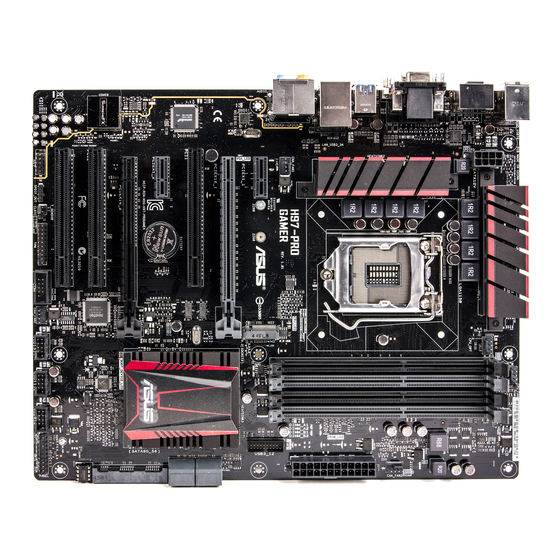
H97-PRO GAMER Place this side towards the rear of the chassis 1.2.3 Motherboard layout 24.4cm(9.6in) KBMS_USB78 CPU_FAN DIGI +VRM CPU_OPT EATX12V 1442K CHA_FAN3 LGA1150 USB3_56 LAN_USB3_34 DRAM_LED H97-PRO CHA_FAN1 AUDIO CPU_LED GAMER PCIEX1_1 Intel VGA_LED I218V PCIEX16_1 PCI1 Intel ® 1083 PCIEX1_2 BATTERY... -
Page 13: Layout Contents
12. TPM connector (20-1 pin TPM) 13. T Sensor connector (2-pin T_SENSOR) 1-22 14. Clear RTC RAM (3-pin CLRTC) 1-13 15. Digital audio connector (4-1 pin SPDIF_OUT) 1-18 16. Front panel audio connector (10-1 pin AAFP) 1-18 Central Processing Unit (CPU) This motherboard comes with a surface mount LGA1150 socket designed for the 4th Generation, New 4th Generation and 5th Generation Intel Core™ i7 / Core™ i5 / Core™ i3, ® Pentium , and Celeron processors. ® ® H97-PRO GAMER H97-PRO GAMER CPU socket LGA1150 ASUS H97-PRO GAMER E9495_H97-PRO_GAMER_Guide.indb 3 2014/6/20 16:05:51... -
Page 14: Installing The Cpu
Unplug all power cables before installing the CPU. • Ensure that you install the correct CPU designed for the LGA1150 socket only. DO NOT install a CPU designed for LGA1155 and LGA1156 sockets on the LGA1150 socket. • Upon purchase of the motherboard, ensure that the PnP cap is on the socket and the socket contacts are not bent. Contact your retailer immediately if the PnP cap is missing, or if you see any damage to the PnP cap/socket contacts/motherboard components. ASUS will shoulder the cost of repair only if the damage is shipment/ transit-related. • Keep the cap after installing the motherboard. ASUS will process Return Merchandise Authorization (RMA) requests only if the motherboard comes with the cap on the LGA1150 socket. • The product warranty does not cover damage to the socket contacts resulting from incorrect CPU installation/removal, or misplacement/loss/incorrect removal of the PnP cap. 1.3.1 Installing the CPU Chapter 1: Product introduction E9495_H97-PRO_GAMER_Guide.indb 4 2014/6/20 16:05:51... -
Page 15: Cpu Heatsink And Fan Assembly Installation
1.3.2 CPU heatsink and fan assembly installation Apply the Thermal Interface Material to the CPU heatsink and CPU before you install the heatsink and fan if necessary. ASUS H97-PRO GAMER E9495_H97-PRO_GAMER_Guide.indb 5 2014/6/20 16:05:51... - Page 16 To install the CPU heatsink and fan assembly To uninstall the CPU heatsink and fan assembly Chapter 1: Product introduction E9495_H97-PRO_GAMER_Guide.indb 6 2014/6/20 16:05:51...
-
Page 17: System Memory
System memory 1.4.1 Overview This motherboard comes with four Double Data Rate 3 (DDR3) Dual Inline Memory Module (DIMM) sockets. A DDR3 module is notched differently from a DDR or DDR2 module. DO NOT install a DDR or DDR2 memory module to the DDR3 slot. According to Intel CPU spec, DIMM voltage below 1.65 V is recommended to protect the ® CPU. H97-PRO GAMER H97-PRO GAMER 240-pin DDR3 DIMM sockets 1.4.2 Memory configurations You may install 2 GB, 4 GB, and 8 GB unbuffered non-ECC DDR3 DIMMs into the DIMM sockets. You can refer to the recommended memory population below. • You may install varying memory sizes in Channel A and Channel B. The system maps the total size of the lower-sized channel for the dual-channel configuration. Any excess memory from the higher-sized channel is then mapped for single-channel operation. • Due to Intel chipset limitation, DDR3 1600 MHz and higher memory modules on XMP ®... -
Page 18: Installing A Dimm
• The default memory operation frequency is dependent on its Serial Presence Detect (SPD), which is the standard way of accessing information from a memory module. • For system stability, use a more efficient memory cooling system to support a full memory load (4 DIMMs). • Visit the ASUS website at www.asus.com for the latest QVL. 1.4.3 Installing a DIMM To remove a DIMM Chapter 1: Product introduction E9495_H97-PRO_GAMER_Guide.indb 8 2014/6/20 16:05:52... - Page 19 H97-PRO GAMER motherboard memory Qualified Vendors Lists (QVL) DDR3 2400MHz Capability DIMM socket support (Optional) Vendors Part No. Size SS/DS Chip Brand Chip NO. Timing Voltage 2 DIMMs 4 DIMMs AG34G2401G1S 4GB 11-12-12-31 1.65V • • DDR3 2250MHz Capability DIMM socket support (Optional) Vendors Part No.
-
Page 20: Expansion Slots
DIMM support: • 2 DIMMs: S upports two (2) modules inserted into either the black slots or the gray slots as one pair of Dual-channel memory configuration. • 4 DIMMs: S upports four (4) modules inserted into both the gray and black slots as two pairs of Dual-channel memory configuration • Visit the ASUS website at www.asus.com for the latest QVL. Expansion slots In the future, you may need to install expansion cards. The following sub-sections describe the slots and the expansion cards that they support. Unplug the power cord before adding or removing expansion cards. Failure to do so may cause you physical injury and damage motherboard components. 1-10 Chapter 1: Product introduction E9495_H97-PRO_GAMER_Guide.indb 10... -
Page 21: Installing An Expansion Card
PCI Express 2.0 x1 slots This motherboard supports PCI Express x1 network cards, SCSI cards, and other cards that comply with the PCI Express specifications. 1.5.5 PCI Express 2.0 x16 slot This motherboard has a PCI Express 2.0 x16 slot that supports PCI Express 2.0 x16 graphic cards complying with the PCI Express specifications. Recommended PCIE expansion cards configuration: PCIE Auto mode M.2 PCIE mode enabled PCIEX1_1 PCIEX1_2 PXIEX16_2 M.2 socket ASUS H97-PRO GAMER 1-11 E9495_H97-PRO_GAMER_Guide.indb 11 2014/6/20 16:05:53... - Page 22 M.2 Socket 3 shares bandwidth with PCIEx1_1 & PCIEx1_2 (in PCIE mode) and SATA6G_4 (in SATA mode), and supports M Key and type 2260/2280 storage devices. Refer to section 2.6.3 PCH Storage Configuration and 2.6.7 Onboard Device Configuration of this user guide for more details. 1.5.6 PCI Express 3.0/2.0 x16 slot This motherboard has a PCI Express 3.0/2.0 x16 slot that supports PCI Express 3.0/2.0 x16 graphic cards complying with the PCI Express specifications. PCI Express operating mode VGA configuration PCIe 3.0/2.0 x16_1 (gray) PCIe 2.0 x16_2 x16 (Recommended for single VGA card) Single VGA/PCIe card Dual VGA/PCIe card •...
-
Page 23: Jumpers
Jumpers Clear RTC RAM (3-pin CLRTC) This jumper allows you to clear the Real Time Clock (RTC) RAM in CMOS. You can clear the CMOS memory of date, time, and system setup parameters by erasing the CMOS RTC RAM data. The onboard button cell battery powers the RAM data in CMOS, which include system setup information such as system passwords. H97-PRO GAMER CLRTC Normal Clear RTC (Default) H97-PRO GAMER Clear RTC RAM To erase the RTC RAM: Turn OFF the computer and unplug the power cord. Move the jumper cap from pins 1-2 (default) to pins 2-3. Keep the cap on pins 2-3 for about 5-10 seconds, then move the cap back to pins 1-2. Plug the power cord and turn ON the computer. Hold down the <Del> key during the boot process and enter BIOS setup to re- enter data. Except when clearing the RTC RAM, never remove the cap on CLRTC jumper default position. Removing the cap will cause system boot failure! • If the steps above do not help, remove the onboard battery and move the jumper again to clear the CMOS RTC RAM data. After clearing the CMOS, reinstall the battery. -
Page 24: Connectors
Connectors 1.7.1 Rear panel connectors PS/2 Mouse/Keyboard combo port. This port connects to a PS/2 mouse or PS/2 keyboard. Optical S/PDIF out port. This port allows you to connect your PC to amplified speakers, headphones, or Sony/Phillips Digital Interconnect Format (S/PDIF) compliant devices. Video Graphics Adapter (VGA) port. This 15-pin port is for a VGA monitor or other VGA-compatible devices. LAN (RJ-45) port. This port allows Gigabit connection to a Local Area Network (LAN) through a network hub. LAN port LED indications Activity Link Speed Activity/Link LED Speed LED Status Description Status... - Page 25 8-channel 2-channel Light Blue Line In Line In Line In Side Speaker Out Lime Line Out Front Speaker Out Front Speaker Out Front Speaker Out Pink Mic In Mic In Mic In Mic In Orange – – Center/Subwoofer Center/Subwoofer Gray – – – Side Speaker Out Black – Rear Speaker Out Rear Speaker Out Rear Speaker Out ASUS H97-PRO GAMER 1-15 E9495_H97-PRO_GAMER_Guide.indb 15 2014/6/20 16:05:54...
-
Page 26: Internal Connectors
This connector is for a serial (COM) port. Connect the serial port module cable to this connector, then install the module to a slot opening at the back of the system chassis. PIN 1 H97-PRO GAMER H97-PRO GAMER Serial port (COM) connector The COM module is purchased separately. CPU and chassis fan connectors (4-pin CPU_FAN, 4-pin CPU_OPT; 4-pin CHA_ FAN1, 4-pin CHA_FAN2, 4-pin CHA_FAN3) Connect the fan cables to the fan connectors on the motherboard, ensuring that the black wire of each cable matches the ground pin of the connector. - Page 27 Power OK -5 Volts +5 Volts H97-PRO GAMER +5 Volts PSON# +3 Volts -12 Volts +3 Volts +3 Volts PIN 1 H97-PRO GAMER ATX power connectors • For a fully configured system, we recommend that you use a power supply unit (PSU) that complies with ATX 12 V Specification 2.0 (or later version) and provides a minimum power of 350 W. • DO NOT forget to connect the 4-pin/8-pin ATX +12V power plug. Otherwise, the system will not boot up. • We recommend that you use a PSU with higher power output when configuring a system with more power-consuming devices or when you intend to install additional devices. The system may become unstable or may not boot up if the power is inadequate.
-
Page 28: Digital Audio Connector
This connector is for a chassis-mounted front panel audio I/O module that supports either HD Audio or legacy AC`97 audio standard. Connect one end of the front panel audio I/O module cable to this connector. H97-PRO AAFP GAMER PIN 1 HD-audio-compliant Legacy AC’97 pin definition compliant definition H97-PRO GAMER Front panel audio connector • We recommend that you connect a high-definition front panel audio module to this connector to avail of the motherboard’s high-definition audio capability. • If you want to connect a high-definition front panel audio module to this connector, set the Front Panel Type item in the BIOS setup to [HD]. If you want to connect an AC’97 front panel audio module to this connector, set the item to [AC97]. By default, this connector is set to [HD]. See section 2.6.7 Onboard Devices Configuration for details. Digital audio connector (4-1 pin SPDIF_OUT) This connector is for an additional Sony/Philips Digital Interface (S/PDIF) port. Connect... - Page 29 USB3+5V IntA_P1_SSRX- IntA_P2_SSRX- IntA_P1_SSRX+ IntA_P2_SSRX+ IntA_P1_SSTX- IntA_P2_SSTX- IntA_P1_SSTX+ IntA_P2_SSTX+ IntA_P1_D- IntA_P2_D- IntA_P1_D+ IntA_P2_D+ H97-PRO GAMER USB3.0 Front panel connector The USB 3.0 module is purchased separately. USB 2.0 connectors (10-1 pin USB910, USB1112, USB1314) These connectors are for USB 2.0 ports. Connect the USB module cable to any of these connectors, then install the module to a slot opening at the back of the system chassis. These USB connectors comply with USB 2.0 specifications and supports up to 480Mbps connection speed. USB1314 USB1112 USB910 H97-PRO GAMER PIN 1 PIN 1 PIN 1 H97-PRO GAMER USB2.0 connectors...
- Page 30 SATA6G_4 RSATA_TXP3 RSATA_TXP4 RSATA_TXN3 RSATA_TXN4 RSATA_RXN3 RSATA_RXN4 RSATA_RXP3 RSATA_RXP4 SATA6G_5 SATA6G_6 H97-PRO GAMER H97-PRO GAMER Intel SATA 6.0Gb/s connectors ® • These connectors are set to [AHCI Mode] by default. If you intend to create a Serial ATA RAID set using these connectors, set the SATA Mode item in the BIOS to [RAID Mode]. Refer to section 2.6.3 PCH Storage Configuration for details. • Before creating a RAID set, refer to the manual bundled in the motherboard support DVD. The SATAEXPRESS connector can support one SATA Express device or two SATA devices. 1-20 Chapter 1: Product introduction E9495_H97-PRO_GAMER_Guide.indb 20...
-
Page 31: System Panel Connector 20-8 Pin Panel
System panel connector (20-8 pin PANEL) This connector supports several chassis-mounted functions. +PWR_LED- SPEAKER H97-PRO GAMER PANEL PIN 1 +HDD_LED- PWR_SW RESET H97-PRO GAMER System panel connector • System power LED (2-pin +PWR_LED-) This 2-pin connector is for the system power LED. Connect the chassis power LED cable to this connector. The system power LED lights up when you turn on the system power, and blinks when the system is in sleep mode. • Hard disk drive activity LED (2-pin +HDD_LED-) This 2-pin connector is for the HDD Activity LED. Connect the HDD Activity LED cable to this connector. The HDD LED lights up or flashes when data is read from or written to the HDD. • System warning speaker (4-pin SPEAKER) This 4-pin connector is for the chassis-mounted system warning speaker. The speaker allows you to hear system beeps and warnings. - Page 32 T Sensor connector (2-pin T_SENSOR) This connector is for the thermistor cable that allows you to monitor the temperature of your motherboard’s critical components and connected devices. H97-PRO GAMER T_SENSOR PIN 1 SENSOR IN H97-PRO GAMER T Sensor connector 1-22 Chapter 1: Product introduction E9495_H97-PRO_GAMER_Guide.indb 22 2014/6/20 16:05:56...
-
Page 33: Onboard Leds
Onboard LEDs Standby Power LED (SB_PWR) The motherboard comes with a standby power LED that lights up to indicate that the system is ON, in sleep mode, or in soft-off mode. This is a reminder that you should shut down the system and unplug the power cable before removing or plugging in any motherboard component. The illustration below shows the location of the onboard LED. H97-PRO GAMER H97-PRO GAMER Onboard LED ASUS H97-PRO GAMER 1-23 E9495_H97-PRO_GAMER_Guide.indb 23 2014/6/20 16:05:56... -
Page 34: Software Support
Operating Systems (OS). Always install the latest OS version and corresponding updates to maximize the features of your hardware. Motherboard settings and hardware options vary. Refer to your OS documentation for detailed information. 1.9.2 Support DVD information The Support DVD that comes with the motherboard package contains the drivers, software applications, and utilities that you can install to avail all motherboard features. The contents of the Support DVD are subject to change at any time without notice. Visit the ASUS website at www.asus.com for updates. To run the Support DVD Place the Support DVD into the optical drive. If Autorun is enabled in your computer, the DVD automatically displays the lists of the unique features of your ASUS motherboard. Click the Drivers, Utilities, AHCI/RAID Driver, Manual, Contact, or Specials tabs to display their respective menus. The following screen is for reference only. Click an icon to display Support... -
Page 35: Bios Information
DVD and a USB flash disk drive. Save a copy of the original motherboard BIOS file to a USB flash disk in case you need to restore the BIOS in the future. Copy the original motherboard BIOS using the ASUS Update utility. -
Page 36: Asus Ez Flash
2.1.2 ASUS EZ Flash 2 The ASUS EZ Flash 2 feature allows you to update the BIOS without using an OS-based utility. Before you start using this utility, download the latest BIOS file from the ASUS website at www.asus.com. To update the BIOS using EZ Flash 2: Insert the USB flash disk that contains the latest BIOS file to the USB port. -
Page 37: Asus Crashfree Bios 3 Utility
2.1.3 ASUS CrashFree BIOS 3 utility The ASUS CrashFree BIOS 3 is an auto recovery tool that allows you to restore the BIOS file when it fails or gets corrupted during the updating process. You can restore a corrupted BIOS file using the motherboard support DVD or a USB flash drive that contains the updated BIOS file. - Page 38 Boot your computer then press <F8> to launch the BIOS Boot Device Select menu. When the BIOS Boot Device Select Menu appears, insert the Support DVD into the optical drive then select the optical drive as the boot device. Please select boot device: ASUS DVD-E818A6T (4069MB) USB DISK 2.0 (3824MB) UEFI: (FAT) USB DISK 2.0 (3824MB)
- Page 39 DO NOT shut down or reset the system while updating the BIOS to prevent system boot failure. Ensure to load the BIOS default settings to ensure system compatibility and stability. Select the Load Optimized Defaults item under the Exit menu for more information. ASUS H97-PRO GAMER E9495_H97-PRO_GAMER_Guide.indb 5 2014/6/20 16:05:58...
-
Page 40: Bios Setup Program
The BIOS setup screens shown in this section are for reference only. Some screen displays may not be the same as what you see on your screen. • Visit the ASUS website at www.asus.com to download the latest BIOS file for this motherboard. •... -
Page 41: Advanced Mode
Advanced Mode The Advanced Mode provides advanced options for experienced end-users to configure the BIOS settings. Refer to the following sections for the detailed configurations. To access the EZ Mode, press F7. ASUS H97-PRO GAMER E9495_H97-PRO_GAMER_Guide.indb 7 2014/6/20 16:05:58... - Page 42 Quick settings bar Configuration fields Hardware information Menu bar General help Menu items Scroll bar Drop-down list Submenu item Last modified Enters EZ settings mode Menu bar The menu bar on top of the screen has the following main items: My Favorites For saving the frequently-used system settings and configuration Main...
-
Page 43: Navigation Keys
This button allows you to enter notes of the activities that you have done in BIOS. Last Modified button This button shows the items that you last modified and saved in BIOS Setup. ASUS H97-PRO GAMER E9495_H97-PRO_GAMER_Guide.indb 9 2014/6/20 16:05:59... -
Page 44: My Favorites
My Favorites MyFavorites is your personal space where you can easily save and access your favorite BIOS items. Adding items to My Favorites To add BIOS items: Press <F3> on your keyboard or click from the BIOS screen to open Setup Tree Map screen. -
Page 45: Main Menu
RAM to clear the BIOS password. See section Jumpers for information on how to erase the RTC RAM. • The Administrator or User Password items on top of the screen show the default Not Installed. After you set a password, these items show Installed. ASUS H97-PRO GAMER 2-11 E9495_H97-PRO_GAMER_Guide.indb 11 2014/6/20 16:06:00... -
Page 46: Administrator Password
Administrator Password If you have set an administrator password, we recommend that you enter the administrator password for accessing the system. Otherwise, you might be able to see or change only selected fields in the BIOS setup program. To set an administrator password: Select the Administrator Password item and press <Enter>. -
Page 47: Ai Tweaker Menu
The configuration options for this section vary depending on the CPU and DIMM model you installed on the motherboard. Scroll down to display the following items: ASUS H97-PRO GAMER 2-13 E9495_H97-PRO_GAMER_Guide.indb 13 2014/6/20 16:06:00... - Page 48 Scroll down to display the following items: Target CPU Turbo-Mode Frequency: xxxxMHz Displays the target CPU Turbo-Mode frequency. Target DRAM Frequency: xxxxMHz Displays the target DRAM frequency. Target Cache Frequency: xxxxMHz Displays the target Cache frequency. Target DMI/PEG Frequency: xxxxMHz Displays the target DMI/PEG frequency.
- Page 49 Allows you to set the memory operating frequency. The configuration options vary with the BCLK Frequency item settings. Selecting a very high frequency may cause the system to become unstable! If this happens, revert to the defualt settings. ASUS H97-PRO GAMER 2-15 E9495_H97-PRO_GAMER_Guide.indb 15 2014/6/20 16:06:01...
-
Page 50: Dram Timing Control
2.5.8 Max. CPU Graphics Ratio [Auto] [Auto] The CPU Graphics Maximum ratio is set to its optimized setting depending on the system loading. [Manual] Use the <+> or <-> keys to adjust the optimal Max. CPU Graphics ratio. The value may vary depending on the system loading. 2.5.9 GPU Boost [Keep Current Settings] GPU Boost accelerates the integrated GPU for extreme graphics performance. - Page 51 Configuration options: [Auto] [1] - [63] DRAM RTL (CHB_R1D0) [Auto] Configuration options: [Auto] [1] - [63] DRAM RTL (CHB_R1D1) [Auto] Configuration options: [Auto] [1] - [63] DRAM IO-L (CHA_R0D0) [Auto] Configuration options: [Auto] [1] - [15] ASUS H97-PRO GAMER 2-17 E9495_H97-PRO_GAMER_Guide.indb 17 2014/6/20 16:06:01...
- Page 52 DRAM IO-L (CHA_R0D1) [Auto] Configuration options: [Auto] [1] - [15] DRAM IO-L (CHA_R1D0 [Auto] Configuration options: [Auto] [1] - [15] DRAM IO-L (CHA_R1D1 [Auto] Configuration options: [Auto] [1] - [15] DRAM IO-L (CHB_R0D0 [Auto] Configuration options: [Auto] [1] - [15] DRAM IO-L (CHB_R0D1 [Auto] Configuration options: [Auto] [1] - [15] DRAM IO-L (CHB_R1D0 [Auto]...
- Page 53 Configuration options: [Enable Both DIMMS] [Disable DIMM0] [Disable DIMM1] [Disable Both DIMMS] Scrambler Setting [Optimized ...] Configuration options: [Optimized (ASUS)] [Default (MRC)] MCH Full Check [Auto] Allows you to enable, disable, or automatically set the MCH Full Check function. Configuration options: [Auto] [Enabled] [Disabled] Skew Control Adjust these items may enhance the DRAM overclocking capability and stability.
- Page 54 2.5.12 DIGI+ VRM CPU Load-Line Calibration [Auto] Load-line is defined by Intel VRM specification and affects CPU voltage. The CPU working voltage will decrease proportionally to CPU loading. Higher value gets a higher voltage and better overclocking performance, but increases the CPU and VRM thermal conditions. This item allows you to adjust the voltage range from the following percentages to boost the system performance.
- Page 55 When enabled, it allows CPU to take precautionary actions when the thermal of the external regulator exceeds the limit. Configuration options: [Auto] [Disabled] [Enabled] CPU Integrated VR Fault Management [Auto] Allows you to manage the CPU Integrated VR fault. Configuration options: [Auto] [Disabled] [Enabled] ASUS H97-PRO GAMER 2-21 E9495_H97-PRO_GAMER_Guide.indb 21 2014/6/20 16:06:01...
- Page 56 CPU Internal Power Configuration CPU Integrated VR Efficiency Management [Auto] Allows you to manage the CPU integrated VR efficiency. Configuration options: [Auto] [High Performance] [Balanced] Power Decay Mode [Auto] Enable to improve power saving on the Fully Integrated Voltage Regulator as the processor enters low current mode.
- Page 57 This item appears only when you set the CPU Cache Voltage to [Offset Mode] and allows you to set the CPU cache voltage offset. The values range from 0.001V to 0.999V with a 0.001V interval. ASUS H97-PRO GAMER 2-23 E9495_H97-PRO_GAMER_Guide.indb 23...
- Page 58 2.5.17 CPU Graphics Voltage [Auto] This item allows you to set the CPU graphics voltage. Increase the graphics voltage when increasing the iGPU frequency. Configuration options: [Auto] [Manual Mode] [Offset Mode] [Adaptive Mode] CPU Graphics Voltage Override [Auto] This item appears only when you set the CPU Graphics Voltage to [Manual Mode] and allows you to set the CPU graphics voltage override.
- Page 59 The system may need better cooling system to work stably under high voltage settings. 2.5.26 DRAM CTRL REF Voltage [Auto] Allows you to set the DRAM CTRL REF Voltage. The values range from 0.3950x to 0.6300x with a 0.0050x interval. ASUS H97-PRO GAMER 2-25 E9495_H97-PRO_GAMER_Guide.indb 25 2014/6/20 16:06:01...
-
Page 60: Advanced Menu
2.5.27 DRAM DATA REF Voltage on CHA [Auto] Allows you to set the DRAM DATA REF Voltage on CHA. The values range from 0.3950x to 0.6300x with a 0.0050x interval 2.5.28 DRAM DATA REF Voltage on CHB [Auto] Allows you to set the DRAM DATA REF Voltage on CHB. The values range from 0.3950x to 0.6300x with a 0.0050x interval 2.5.29 CPU Spread Spectrum [Auto]... - Page 61 Allows a hardware platform to perform adjacent cache line prefetching. [Disabled] Disables this function. Boot performance mode [Max Non-Turbo Performance] This item allows you to select the boot performance mode. Configuration options: [Max Non- Turbo Performance] [Max battery] [Turbo Performance] ASUS H97-PRO GAMER 2-27 E9495_H97-PRO_GAMER_Guide.indb 27 2014/6/20 16:06:01...
- Page 62 CPU Power Management Configuration This item allows you to manage and configure the CPU’s power. Enhanced Intel Speedstep Technology [Enabled] Allows you to enable or disable the Enhanced Intel SpeedStep Technology (EIST). ® [Disabled] The CPU runs at its default speed. [Enabled] The operating system controls the CPU speed.
-
Page 63: Pch Configuration
PCH Storage Configuration While entering Setup, the BIOS automatically detects the presence of SATA devices. The SATA Port items show Not Present if no SATA device is installed to the corresponding SATA port. ASUS H97-PRO GAMER 2-29 E9495_H97-PRO_GAMER_Guide.indb 29 2014/6/20 16:06:02... - Page 64 The system automatically adjust the SRIS (Separate Reference Clock Independent Spread Spectrum Clocking Architecture) support for connected SATA Express devices. [Disabled] Select this option for ASUS RUNWAY SATA Express bridge card. SATA Mode Selection [AHCI] Allows you to set the SATA configuration. [Disabled] Disables the SATA function.
-
Page 65: System Agent Configuration
Allows you to enable or disable DMI Gen 2. Configuration options: [Auto] [Enabled] [Disabled] NB PCI-E Configuration Allows you to configure the NB PCI Express settings. PCI-EX16_1 Link Speed [Auto] Allows you to configure the PCI-EX16_1 speed. Configuration options: [Auto] [Gen1] [Gen2] [Gen3] ASUS H97-PRO GAMER 2-31 E9495_H97-PRO_GAMER_Guide.indb 31 2014/6/20 16:06:02... -
Page 66: Memory Configuration
Memory Configuration Memory Scrambler [Enabled] Allows you to enable or disable Memory Scrambler support. Memory Remap [Enabled] Allows you to enable or disable remapping the memory above 4GB. [Enabled] Enables the function. [Disabled] Disables this function. 2.6.5 USB Configuration The items in this menu allow you to change the USB-related features. The USB Devices item shows the auto-detected values. -
Page 67: Onboard Devices Configuration
ASPM to take effect. Configuration options: [Disabled] [L0s] [L1] [L0sL1] PEG ASPM Support [Disabled] This item allows you to select the ASPM state for energy-saving conditions, or use the ASUS optimized energy saving profile. Configuration options: [Disabled] [ASPM] [L0s] [L1] [L0sL1] [Auto] 2.6.7... -
Page 68: Serial Port Configuration
SPDIF Out Type [SPDIF] [SPDIF] Sets to an SPDIF audio output. [HDMI] Sets to an HDMI audio output. SupremeFX Lighting LED [Enabled] Allows you to enable or disable the SupremeFX Lighting LED. Configuration options: [Enabled] [Disabled] M.2 PCIe Mode Socket [Disabled] Allows you to enable or disable the M.2 (PCIE Mode) socket. -
Page 69: Network Stack Configuration
The following two items appear only when you set the previous item to [Enabled]. Ipv4 PXE Support [Enabled] This item allows user to disable or enable the Ipv4 PXE Boot support. Configuration options: [Disable Link] [Enabled] ASUS H97-PRO GAMER 2-35 E9495_H97-PRO_GAMER_Guide.indb 35 2014/6/20 16:06:02... -
Page 70: Monitor Menu
Ipv6 PXE Support [Enabled] This item allows user to disable or enable the Ipv6 PXE Boot support. Configuration options: [Disable Link] [Enabled] Monitor menu The Monitor menu displays the system temperature/power status, and allows you to change the fan settings. Scroll down to display the following items: 2-36 Chapter 2: Getting started... - Page 71 CPU Input Voltage (VCCIN), CPU Core Voltage, 3.3V Voltage, 5V Voltage, 12V Voltage The onboard hardware monitor automatically detects the voltage output through the onboard voltage regulators. Select Ignore if you do not want to detect this item. ASUS H97-PRO GAMER 2-37 E9495_H97-PRO_GAMER_Guide.indb 37 2014/6/20 16:06:03...
- Page 72 2.7.5 CPU Q-Fan Control [Auto] [Auto] Enables the CPU Q-Fan control for 4-pin CPU fan. [Disabled] Disables the CPU Q-Fan control feature. [PWM Mode] Enable the CPU Q-Fan control in PWM mode for 4-pin CPU fan. [DC Mode] Enable the CPU Q-Fan control in DC mode for 3-pin CPU fan. CPU Fan Speed Low Limit [300 RPM] This item appears only when you enable the CPU Q-Fan Control feature and allows you to disable or set the CPU fan warning speed.
- Page 73 20% to 100%. When the chassis temperature reaches the upper limit, the chassis fan will operate at the maximum duty cycle. Chassis Fan 1/2/3 Middle Temperature [45] Use the <+> or <-> keys to set the value for Chassis Fan Middle Temperature. ASUS H97-PRO GAMER 2-39 E9495_H97-PRO_GAMER_Guide.indb 39 2014/6/20 16:06:03...
- Page 74 Chassis Fan 1/2/3 Middle Duty Cycle(%) [60] Use the <+> or <-> keys to adjust the chassis fan middle duty cycle. The values range from 20% to 100%. Chassis Fan 1/2/3 Lower Temperature [40] Use the <+> or <-> keys to adjust the chassis fans’ lower temperature. The values range from 20% to 75%.
-
Page 75: Boot Menu
Scroll down to display the following items: 2.8.1 Fast Boot [Enabled] [Enabled] Select to accelerate the boot speed. [Disabled] Select to go back to normal boot. The following four items appear when you set Fast Boot to [Enabled]. ASUS H97-PRO GAMER 2-41 E9495_H97-PRO_GAMER_Guide.indb 41 2014/6/20 16:06:04... - Page 76 SATA Support [All Devices] [All Devices] All devices connected to SATA ports will be available during POST. This process will extend the POST time. [Hard Drive Only] Only hard drives connected to SATA ports will be detected during POST. Any hardware change will disable fast boot. [Boot Drive Only] Only boot drive connected to SATA ports will be detected during POST.
- Page 77 Option ROM Messages [Enabled] [Enabled] The option ROM messages will be shown during the POST (power-on self- test). [Disabled] Only the ASUS logo will be shown during the POST. 2.8.6 Interrupt 19 Capture [Disabled] [Enabled] Allows the option ROMs to trap Interrupt 19.
-
Page 78: Secure Boot
[Enabled] For better compatibility, enable the CSM to fully support the non-UEFI driver add-on devices or the Windows UEFI mode. ® [Disabled] Disable the CSM to fully support the Windows Security Update and ® Security Boot. The following four items appear when you set Launch CSM to [Enabled]. Boot Device Control [UEFI and Legacy OPROM] Allows you to select the type of devices that you want to boot up. - Page 79 The KEK file must be formatted as a UEFI variable structure with time-based authenticated variable. DB Management The db (Authorized Signature database) lists the signers or images of UEFI applications, operating system loaders, and UEFI drivers that you can load on the single computer. ASUS H97-PRO GAMER 2-45 E9495_H97-PRO_GAMER_Guide.indb 45 2014/6/20 16:06:04...
-
Page 80: Boot Option Priorities
• To select the boot device during system startup, press <F8> when ASUS Logo appears. • To access Windows OS in Safe Mode, do any of the following: Press <F5>... -
Page 81: Tool Menu
<Enter> to display the submenu. 2.9.1 ASUS EZ Flash 2 Utility Allows you to run ASUS EZ Flash 2. Press <Enter> to launch the ASUS EZ Flash 2 screen. For more details, see section ASUS EZ Flash 2. Setup Animator [Enabled] This item allows you to enable or disable the Setup animator. -
Page 82: Asus Spd Information
2.9.3 ASUS SPD Information DIMM Slot # [Slot 1] Displays the Serial Presence Detect (SPD) information of the DIMM module installed on the selected slot. Configuration options: [DIMM_A1] [DIMM_A2] [DIMM_B1] [DIMM_B2] 2.10 Exit menu The Exit menu items allow you to load the optimal default values for the BIOS items, and save or discard your changes to the BIOS items. -
Page 83: Appendices
: (1) cet appareil ne doit pas provoquer d’interférences et (2) cet appareil doit accepter toute interférence, y compris celles susceptibles de provoquer un fonctionnement non souhaité de l’appareil. H97-PRO GAMER E9495_H97-PRO_GAMER_Guide.indb 1 2014/6/20 16:06:05... -
Page 84: Canadian Department Of Communications Statement
ASUS Recycling/Takeback Services ASUS recycling and takeback programs come from our commitment to the highest standards for protecting our environment. We believe in providing solutions for you to be able to responsibly recycle our products, batteries, other components as well as the packaging materials. -
Page 85: Asus Contact Information
+1-510-739-3777 +1-510-608-4555 Web site http://www.asus.com/us/ Technical Support General support +1-812-282-2787 Support fax +1-812-284-0883 Online support http://www.service.asus.com/ ASUS COMPUTER GmbH (Germany and Austria) Address Harkort Str. 21-23, D-40880 Ratingen, Germany +49-2102-959931 Web site http://www.asus.com/de Online contact http://www.asus.de/sales Technical Support Telephone +49-2102-5789555... - Page 86 Appendices E9495_H97-PRO_GAMER_Guide.indb 4 2014/6/20 16:06:05...
Need help?
Do you have a question about the H97-PRO GAMER and is the answer not in the manual?
Questions and answers