Carrier 33CS Installation, Service, And Troubleshooting Instructions
Temp system unitary controller thermostat
Hide thumbs
Also See for 33CS:
Table of Contents
Advertisement
Troubleshooting Instructions
GENERAL . . . . . . . . . . . . . . . . . . . . . . . . . . . . . . . . . . . . . . . . 2
TEMP System Components . . . . . . . . . . . . . . . . . . . . . . 2
INSTALLATION . . . . . . . . . . . . . . . . . . . . . . . . . . . . . . . . . 2-4
Thermostat Placement . . . . . . . . . . . . . . . . . . . . . . . . . . . 2
Wiring Requirements. . . . . . . . . . . . . . . . . . . . . . . . . . . . . 2
Relay Pack Installation . . . . . . . . . . . . . . . . . . . . . . . . . . . 4
Wiring Connections . . . . . . . . . . . . . . . . . . . . . . . . . . . . . . 4
Indoor-Air Quality Sensor Installation . . . . . . . . . . . . 4
Provide Power To Relay Pack. . . . . . . . . . . . . . . . . . . . . 4
CONFIGURATION . . . . . . . . . . . . . . . . . . . . . . . . . . . . . . 4-8
Manual Configuration . . . . . . . . . . . . . . . . . . . . . . . . . . . . 4
Computer Configuration . . . . . . . . . . . . . . . . . . . . . . . . . 4
TEMP SYSTEM THERMOSTAT DISPLAY . . . . . . . . . . 9
System Status Display . . . . . . . . . . . . . . . . . . . . . . . . . . . 9
Rotating Display . . . . . . . . . . . . . . . . . . . . . . . . . . . . . . . . . 9
Electronic Timeclock . . . . . . . . . . . . . . . . . . . . . . . . . . . . . 9
Alternate Information Display . . . . . . . . . . . . . . . . . . . . 9
Display Freeze . . . . . . . . . . . . . . . . . . . . . . . . . . . . . . . . . . . 9
START-UP . . . . . . . . . . . . . . . . . . . . . . . . . . . . . . . . . . . . . .9,10
Device Address . . . . . . . . . . . . . . . . . . . . . . . . . . . . . . . . . . 9
Device Bus Number . . . . . . . . . . . . . . . . . . . . . . . . . . . . . 10
Device Access Security Level . . . . . . . . . . . . . . . . . . . 10
COMMUNICATIONS . . . . . . . . . . . . . . . . . . . . . . . . . . . . . 10
Information Broadcast . . . . . . . . . . . . . . . . . . . . . . . . . . 10
Communication Check . . . . . . . . . . . . . . . . . . . . . . . . . . 10
OCCUPIED MODE OPERATION. . . . . . . . . . . . . . . .10,11
Occupied Set Points . . . . . . . . . . . . . . . . . . . . . . . . . . . . 10
Occupied Set Point Limiting. . . . . . . . . . . . . . . . . . . . . 11
UNOCCUPIED MODE OPERATION . . . . . . . . . . . .11,12
Unoccupied Set Points . . . . . . . . . . . . . . . . . . . . . . . . . . 11
Occupancy Schedules . . . . . . . . . . . . . . . . . . . . . . . . . . 11
Schedule Number . . . . . . . . . . . . . . . . . . . . . . . . . . . . . . 12
Unoccupied Override. . . . . . . . . . . . . . . . . . . . . . . . . . . . 12
Optimal Start . . . . . . . . . . . . . . . . . . . . . . . . . . . . . . . . . . . . 12
SENSORS . . . . . . . . . . . . . . . . . . . . . . . . . . . . . . . . . . . . 12-15
Zone Temperature Sensor. . . . . . . . . . . . . . . . . . . . . . . 12
Zone Temperature Monitoring . . . . . . . . . . . . . . . . . . . 13
Remote Room Temperature Sensor . . . . . . . . . . . . . 13
Duct Temperature Sensor . . . . . . . . . . . . . . . . . . . . . . . 13
DX Coil Temperature Sensor . . . . . . . . . . . . . . . . . . . . 13
Outside-Air Temperature Sensor . . . . . . . . . . . . . . . . 14
Indoor-Air Humidity Sensor . . . . . . . . . . . . . . . . . . . . . 14
Indoor-Air Quality Sensor . . . . . . . . . . . . . . . . . . . . . . . 14
Fan/Filter Status Switch . . . . . . . . . . . . . . . . . . . . . . . . . 15
EQUIPMENT. . . . . . . . . . . . . . . . . . . . . . . . . . . . . . . . . . 15-18
Heating/Cooling Equipment Interface . . . . . . . . . . . 15
System Switches . . . . . . . . . . . . . . . . . . . . . . . . . . . . . . . . 15
Fan Switch . . . . . . . . . . . . . . . . . . . . . . . . . . . . . . . . . . . . . . 16
Fan Operation For Heat . . . . . . . . . . . . . . . . . . . . . . . . . 16
Zone Caller. . . . . . . . . . . . . . . . . . . . . . . . . . . . . . . . . . . . . . 16
Manufacturer reserves the right to discontinue, or change at any time, specifications or designs without notice and without incurring obligations.
PC 111
Book 1
4
Tab
11a 13a
Installation, Service, and
Page
Catalog No. 533-344
Printed in U.S.A.
Unitary Controller Thermostat
CONTENTS
System Mode . . . . . . . . . . . . . . . . . . . . . . . . . . . . . . . . . . . 16
Equipment Operation . . . . . . . . . . . . . . . . . . . . . . . . . . . 16
Control. . . . . . . . . . . . . . . . . . . . . . . . . . . . . . . . . . . . . . . . 16
Optimize Staging. . . . . . . . . . . . . . . . . . . . . . . . . . . . . . . . 17
System Status Display . . . . . . . . . . . . . . . . . . . . . . . . . . 17
System Time Guards . . . . . . . . . . . . . . . . . . . . . . . . . . . . 17
Temperature Lockouts . . . . . . . . . . . . . . . . . . . . . . . . . . 18
Heating Lockout Temperature Set Point . . . . . . . . . 18
Cooling Lockout Temperature Set Point . . . . . . . . . 18
Pre-Occupancy Purge . . . . . . . . . . . . . . . . . . . . . . . . . . . 18
METERING . . . . . . . . . . . . . . . . . . . . . . . . . . . . . . . . . . . . . . 19
HVAC Usage Meter . . . . . . . . . . . . . . . . . . . . . . . . . . . . . . 19
Override Usage Meter . . . . . . . . . . . . . . . . . . . . . . . . . . . 19
HVAC Override Usage Meter . . . . . . . . . . . . . . . . . . . . 19
DIAGNOSTICS . . . . . . . . . . . . . . . . . . . . . . . . . . . . . . . 19-24
Error Code Display . . . . . . . . . . . . . . . . . . . . . . . . . . . . . . 19
System Errors (SE). . . . . . . . . . . . . . . . . . . . . . . . . . . . . . 19
Storage Failure (SF) Errors . . . . . . . . . . . . . . . . . . . . . . 21
Hardware Failure (HF) Errors . . . . . . . . . . . . . . . . . . . . 23
TEMP System Thermostat Reset . . . . . . . . . . . . . . . . 24
BROADCAST/DAYLIGHT SAVINGS TIME . . . . . .24,25
Network Time Broadcast . . . . . . . . . . . . . . . . . . . . . . . . 24
Network Time Request . . . . . . . . . . . . . . . . . . . . . . . . . . 24
Receive Network Time . . . . . . . . . . . . . . . . . . . . . . . . . . 24
Broadcast Acknowledger . . . . . . . . . . . . . . . . . . . . . . . 24
Global Schedule Broadcast . . . . . . . . . . . . . . . . . . . . . 25
Daylight Savings Time . . . . . . . . . . . . . . . . . . . . . . . . . . 25
HOLIDAY SCHEDULES . . . . . . . . . . . . . . . . . . . . . . . . . . 25
ALARM OPTIONS . . . . . . . . . . . . . . . . . . . . . . . . . . . . . . . 26
Equipment Priority . . . . . . . . . . . . . . . . . . . . . . . . . . . . . . 26
Communication Failure Retry Time. . . . . . . . . . . . . . 26
Re-Alarm Time . . . . . . . . . . . . . . . . . . . . . . . . . . . . . . . . . . 26
Alarm Routing Control . . . . . . . . . . . . . . . . . . . . . . . . . . 26
Alarm System Name . . . . . . . . . . . . . . . . . . . . . . . . . . . . 26
LOADSHED . . . . . . . . . . . . . . . . . . . . . . . . . . . . . . . . . . . . . 26
ALARM TROUBLESHOOTING . . . . . . . . . . . . . . . . 26-29
(Comfort Trend) . . . . . . . . . . . . . . . . . . . . . . . . . . . . . . . 26
(Heat/Cool Mode Error). . . . . . . . . . . . . . . . . . . . . . . . 27
Fan Status Alarm. . . . . . . . . . . . . . . . . . . . . . . . . . . . . . . . 27
Filter Status Alert . . . . . . . . . . . . . . . . . . . . . . . . . . . . . . . 28
Indoor-Air Quality Status Alarm . . . . . . . . . . . . . . . . . 28
Stuck Gas Valve Alarm . . . . . . . . . . . . . . . . . . . . . . . . . . 29
NETWORK ACCESSIBLE VARIABLES . . . . . . . . .29,30
TROUBLESHOOTING PROCEDURES. . . . . . . . . .30,31
General Operating Problems . . . . . . . . . . . . . . . . . . . . 30
Equipment Operation Problems . . . . . . . . . . . . . . . . . 31
INDEX . . . . . . . . . . . . . . . . . . . . . . . . . . . . . . . . . . . . . . . . . . . 32
Form 33CS-29SI
33CS
TEMP System
Pg 1
4-00
Replaces: VTS-2SI
Page
Advertisement
Chapters
Table of Contents
Troubleshooting

Related Manuals for Carrier 33CS


Summary of Contents for Carrier 33CS
-
Page 1: Table Of Contents
Zone Caller........16 Manufacturer reserves the right to discontinue, or change at any time, specifications or designs without notice and without incurring obligations. PC 111 Catalog No. 533-344 Printed in U.S.A. Form 33CS-29SI Pg 1 4-00 Replaces: VTS-2SI Book 1... -
Page 2: General
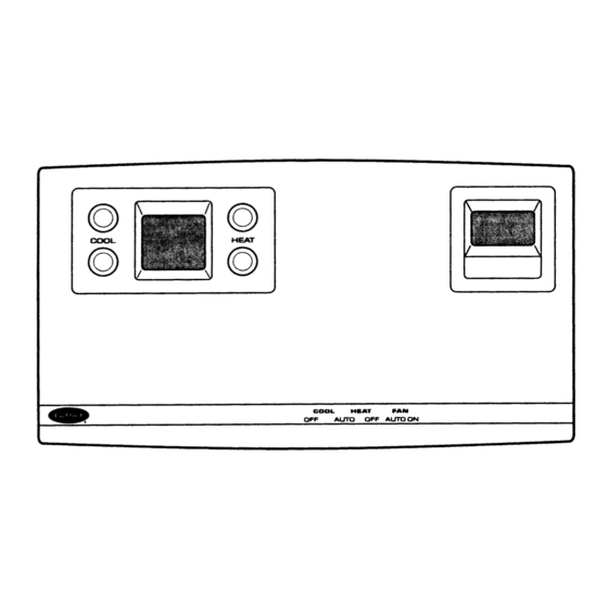
The Carrier Comfort System TEMP System is designed to The thermostat should be located on an interior wall, about be compatible with the full line of Carrier single-zone heating 5 ft from the ground. The thermostat should be located away and cooling units. - Page 3 FRONT VIEW SIDE VIEW Fig. 1 — TEMP System Thermostat with Timeclock FRONT VIEW SIDE VIEW Fig. 2 — TEMP System Thermostat without Timeclock...
-
Page 4: Relay Pack Installation
(IAQ) sensor is designed for use with the displayed, along with the current option number. The escape Carrier Comfort system. The sensor has a range of 0 to (right upper set point) button can be used to return to the cate- 5000 ppm of CO . - Page 5 LEGEND — Direct Expansion Coil Sensor IAQ — Indoor-Air Quality Sensor FSS — Filter Status Sensor OAT — Outdoor-Air Temperature Sensor NOTE: Humidity Sensor and Filter Status Switch — Humidity Sensor SAT — Supply-Air Temperature Sensor cannot be wired at the same time. Fig.
- Page 6 Fig. 4 — Relay Pack Wiring without Auxiliary Relay (TSR-01) Fig. 5 — Relay Pack Wiring with Auxiliary Relay (33CSUCE-06)
- Page 7 Fig. 6 — TEMP System Thermostat Display Screen Fig. 7 — TEMP System Thermostat Configuration Buttons Table 1 — TEMP System Thermostat Categories and Options OPTION DESCRIPTION DEFAULT MINIMUM MAXIMUM CATEGORY 1.0 SET POINTS Cooling Set Point Low Limit (F) Heating Set Point High Limit (F) Unoccupied Cooling Set Point (F) Unoccupied Heating Set Point (F)
- Page 8 Table 1 — TEMP System Thermostat Categories and Options (cont) OPTION DESCRIPTION DEFAULT MINIMUM MAXIMUM 5.10 Fan Status Switch Humidity Sensor/Filter Status (0 — No Sensor, 1 — Indoor Humidity 5.11 Sensor, 2 — Filter Status Switch) 5.12 Humidity Sensor Calibration Indoor Humidity CATEGORY 6.0 SUPPLEMENTAL HEAT No configuration needed.
-
Page 9: Temp System Thermostat Display
Press the select button to The Device Address option allows the TEMP system ther- return to normal timeclock operation. Re-install the thermostat mostat to establish an identity on the Carrier network for trans- cover. mitting and receiving information. The device address is set in NOTE: If the TEMP system thermostat receives time from a category 8, option 1. -
Page 10: Device Bus Number
Device Bus Number — completed the system scan, the Communication Check is auto- There can be secondary busses matically deactivated. connected to a single primary bus. On the primary bus, each secondary bus has an address. When the TEMP system prima- During a Communication Check, the TEMP system ther- ry thermostat resides on a secondary bus, the bus address must mostat scans consecutive device addresses starting with the de-... -
Page 11: Occupied Set Point Limiting
Occupied Set Point Limiting — unoccupied mode. The range of allowable temperatures is 50 to The occupied set 99 F for heating or cooling. point limits establish the maximum allowable heating set point and the minimum allowable cooling set point. The range of To configure the unoccupied cooling set point, enter catego- allowable temperature limits is 50 to 99 F for heating and ry 1, option 3. -
Page 12: Schedule Number
Start Time — When the select button is pressed from the first CUT BACK AND SHIELD RED + CONNECTED TO TAPE DOWN SHIELD option screen, the hours number will flash. The hours are mod- EARTH/CHASSIS ified through the left set point buttons. The AM/PM modifier GROUND will automatically switch when scrolling through the times. -
Page 13: Zone Temperature Monitoring
option 2. The temperature reading of the sensor will be dis- played. Compare the reading to an accurate thermometer. Use the left upper or lower set point buttons to raise or lower the temperature reading (by tenths of a degree) until the desired calibrated temperature is shown. -
Page 14: Outside-Air Temperature Sensor
The Comfort IAQ fea- the TEMP system thermostat will not use information from the ture allows the Carrier Comfort system to interface with the temperature sensor for high and low temperature limits. economizer on the HVAC equipment and maintain the quality To configure the DX Coil Temperature Sensor option, con- of indoor air within acceptable limits. -
Page 15: Sensors
Set Point option will keep the IAQ mode from beginning To protect the equipment, the TEMP system thermostat unless the outdoor humidity is below acceptable levels. The utilizes a time guard function to prevent excessive equipment option is configured in category 14, option 4. The set point can cycling. -
Page 16: Fan Switch
To control the cool switch setting, configure category 4, • the Heating or Cooling Temperature Lockouts option is set option 19. These range is from 0 to 2. When the option is set to to ON and the outside-air temperature exceeds the lockout 0, the thermostat will use the setting of the mechanical cool temperature set point. -
Page 17: Optimize Staging
EQUIPMENT OPERATION DURING A SYSTEM COOL- The TEMP system thermostat uses Optimized Staging to ING MODE follow zone conditions and determine when use of first stage is improving zone conditions. If zone conditions are not improv- Outside-Air Temperature Greater Than 65 F — The TEMP ing, or are becoming worse, the TEMP system thermostat will system thermostat utilizes the relay pack to energize the first energize the second stage of heating or cooling. -
Page 18: Temperature Lockouts
To configure the Second Stage Cooling Temperature Limit system thermostat is powered up. The length of the time guard option, set category 4, option 6. Use the left set point buttons to is 5 minutes plus 0 to 189 seconds (determined by the first 6 raise or lower the set point until the desired temperature is bits of the address of the heating/cooling equipment). -
Page 19: Metering
METERING The 3 numbers located in the top of the display identify the specific error. The TEMP system thermostat has zone metering capabili- When the Error Code Display option is ON, an error code ties. The available functions allow the TEMP system thermo- will be displayed when the associated error occurs. -
Page 20: Heating Mode Error Set Point (F)
To troubleshoot a Comfort Trend Error: continuously for 10 minutes. During a system cooling mode, an SE08 error occurs when the supply-air temperature is higher 1. Check the quantity of airflow into the TEMP system ther- than the Cooling Mode Error Set Point. During a system heat- mostat zone. -
Page 21: Storage Failure (Sf) Errors
If the lockouts prevent IAQ mode from operating, the warmed to set point. This causes the heated air to be recirculat- system will not enter IAQ mode. These lockouts are user- ed back through the unit, further aggravating the overheating configured and measure outdoor humidity (category 14, problem. -
Page 22: Off
Table 4 — Storage Failure (SF) Errors (cont) ERROR INFORMATION AFFECTED DEFAULT VALUE(S) SF16 Occupancy Period 8 – SF17 Schedule Number SF18 Override Time Limit SF28 Fan Operation For Heat SF30 Time Guard Between Modes SF32 LAT Monitoring SF33 First Stage Cooling Temperature Limit SF34 Second Stage Cooling Temperature Limit First Stage Heating Temperature Limit... -
Page 23: Hardware Failure (Hf) Errors
Hardware Failure (HF) Errors — thermostat using the Remote Room Sensor Calibration A Hardware Fail- function (category 5, option 3) and an accurate thermom- ure (HF) error is an error that corresponds to a hardware failure eter. Measure the temperature at the remote room temper- at the TEMP system thermostat, associated sensors, or zone ature sensor location using the accurate thermometer. -
Page 24: Temp System Thermostat Reset
OUTDOOR-AIR TEMPERATURE SENSOR OUT OF RANGE — An HF10 error is issued when the outdoor-air As a part of the Carrier Comfort system, on the network, the temperature sensor is reading below –40 F or greater than TEMP system thermostat can send and receive broadcasts. -
Page 25: Global Schedule Broadcast
To set the option, configure category 9, option 1. Use the raise or lower the value. The range of values is 0 to 90 minutes. left set point buttons to toggle the option ON or OFF. The de- The default is 60 minutes. fault is OFF. -
Page 26: Alarm Options
The alarms options of the TEMP system thermostat are re- turn off second stage heating or cooling operation if the second sponsible for transmitting alarms on the CCN (Carrier Comfort stage is currently operating and not allow second stage heating Network). -
Page 27: Discharge-Air Temperature Alarm
CONFIGURATION TO ACTIVATE ALARM — To activate CONFIGURATION TO NORMALIZE ALARM — When a space temperature alarm, configure the Comfort Trend unit discharge temperature rises above the heat mode error set Demand set point to any value except 0. Configure the Com- point, the heat mode alarm is normalized. -
Page 28: Filter Status Alert
When alarm condition is initiated: Pressure drop across the filters in the unit increases until it reaches the Filter Status sensor’s set point. This causes the con- • the TEMP system thermostat will continue to operate tacts of the sensor to close. The contact closure of the sensor is the system. -
Page 29: Stuck Gas Valve Alarm
When the CO level exceeds the preset level (factory con- During a Cooling Mode — If the duct temperature does not figuration is 1000 ppm and cannot be changed without optional drop below 80 F within 10 minutes, the cooling mode will be software), the sensor signals the TEMP system thermostat. -
Page 30: Troubleshooting Procedures
Table 13 — Network Software Access contained within memory with factory selected default Table Names values. • System Errors (SE). These errors occur when the TEMP TABLE DESCRIPTION TABLE NAME system thermostat detects a system or zone operating prob- Points Display Table ZONESTAT lem. -
Page 31: Equipment Operation Problems
To return the blinking display to normal: system thermostat to energize the second stage of heating or cooling. 1. The display will return to normal when the supply air temperature returns to within the limits of the current sys- 1. When a system mode is selected and the reference zone tem operating mode. -
Page 32: Index
Indoor-Air Quality Low Temperature Lockout, 15 Zone Temperature Sensor Calibration, 12 Indoor-Air Quality Maximum Space Temperature Reset, 14 Copyright 2000 Carrier Corporation Manufacturer reserves the right to discontinue, or change at any time, specifications or designs without notice and without incurring obligations. Book 1 PC 111 Catalog No.