Carrier 33CS Installation Instructions
Temp system thermostat, monitor thermostat
zone controller, bypass controller, linkage thermostat
Hide thumbs
Also See for 33CS:
Advertisement
Zone Controller, Bypass Controller, Linkage Thermostat
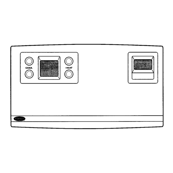
Fig. 1 — Monitor Thermostat or TEMP System Thermostat with Timeclock,
Fig. 2 — Monitor Thermostat or TEMP System Thermostat Without Timeclock,
Manufacturer reserves the right to discontinue, or change at any time, specifications or designs without notice and without incurring obligations.
Book 1
4
PC 111
Tab
11a 13a
TEMP System Thermostat, Monitor Thermostat
Installation Instructions
These installation instructions are for the wall mounting of
the TEMP system thermostat 33CSTM(T)-01, the VVT
system monitor thermostat 33CSVM(T)-32, the VVT sys-
tem zone controller 33CSZC--01, the VVT system bypass
controller 33CSBC--00, and the Linkage Thermostat
33CSKITLST-08. See Fig. 1 and 2.
or Linkage Thermostat
Zone Controller, or Bypass Controller
Catalog No. 533-339
Printed in U.S.A.
GENERAL
Form 33CS-25SI
33CS
Pg 1
4-98
Replaces: 33CS-1SI
Advertisement
Table of Contents

Related Manuals for Carrier 33CS


Summary of Contents for Carrier 33CS
-
Page 1: Installation Instructions
Zone Controller, or Bypass Controller Manufacturer reserves the right to discontinue, or change at any time, specifications or designs without notice and without incurring obligations. Book 1 PC 111 Catalog No. 533-339 Printed in U.S.A. Form 33CS-25SI Pg 1 4-98 Replaces: 33CS-1SI 11a 13a... - Page 2 Test before attaching to relay pack or damper actuator. To mount the thermostat, perform the following: Call the local Carrier representative if more information 1. Cut a hole in the wall for the terminal board housing. The is needed about wiring.
- Page 3 Fig. 4 — Wiring Connections (Monitor Thermostat, Zone Controller, Bypass Controller, or TEMP System Thermostat)
- Page 4 Fig. 5 — Wiring Connections (Linkage Thermostat) Fig. 6 — Terminal Board Installation Copyright 1998 Carrier Corporation Manufacturer reserves the right to discontinue, or change at any time, specifications or designs without notice and without incurring obligations. Book 1 PC 111 Catalog No.
Need help?
Do you have a question about the 33CS and is the answer not in the manual?
Questions and answers