Table of Contents
Advertisement
Quick Links
Advertisement
Table of Contents

Related Manuals for AlphaGen DCX3000


Summary of Contents for AlphaGen DCX3000
- Page 2 The engine exhaust from this product contains chemicals known to the State of California to cause cancer, birth defects or other reproductive harm. Keep this owner’s manual handy, so you can refer to it at any time. This owner’s manual is considered a permanent part of the generator and should remain with the generator if resold.
- Page 3 INTRODUCTION Congratulations on your selection of this generator. We are certain you will be pleased with your purchase of one of the finest generators on the market. We want to help you get the best results from your new generator and to operate it safely.
- Page 4 A FEW WORDS ABOUT SAFETY Your safety and the safety of others are very important. And using this generator safely is an important responsibility. To help you make informed decisions about safety, we have provided operating procedures and other information on labels and in this manual.
-
Page 5: Table Of Contents
CONTENTS GENERATOR SAFETY IMPORTANT SAFETY INFORMATION Operator Responsibility Carbon Monoxide Hazards Electric Shock Hazards Fire and Burn Hazards Refuel With Care SAFETY LABEL LOCATIONS CONTROLS & FEATURES COMPONENT & CONTROL LOCATIONS CONTROLS DC Voltage Selector Switch Fuel Valve Lever Choke Knob Engine Switch Recoil Starter Output Switch... - Page 6 CONTENTS OPERATION SAFE OPERATING PRECAUTIONS STARTING THE ENGINE/DC OPERATION Forced Output STOPPING THE ENGINE SERVICING YOUR GENERATOR THE IMPORTANCE OF MAINTENANCE MAINTENANCE SAFETY Safety Precautions MAINTENANCE SCHEDULE REFUELING FUEL RECOMMENDATIONS ENGINE OIL LEVEL CHECK ENGINE OIL CHANGE ENGINE OIL RECOMMENDATIONS AIR CLEANER SERVICE FOAM AIR FILTER CLEANING SEDIMENT CUP CLEANING...
- Page 7 STORAGE STORAGE PREPARATION Cleaning Fuel Engine Preparation STORAGE PRECAUTIONS REMOVAL FROM STORAGE TRANSPORTING TAKING CARE OF UNEXPECTED PROBLEMS ENGINE PROBLEMS GENERATOR PROBLEMS TECHNICAL & CONSUMER INFORMATION TECHNICAL INFORMATION Serial Number Location Carburetor Modification for High Altitude Operation Oxygenated Fuels Emission Control System Information Air Index Specifications Wiring Diagram...
-
Page 8: Generator Safety
GENERATOR SAFETY IMPORTANT SAFETY INFORMATION This generator is designed for use with CATV/Telecommunications equipment that has suitable power requirements. Other uses can result in injury to the operator or damage to the generator and other property. Most accidents can be prevented if you follow all instructions in this manual and on the generator. -
Page 9: Electric Shock Hazards
Electric Shock Hazards The generator produces enough electric power to cause a serious shock or electrocution if misused. Do not touch uninsulated portion of output coupler. Risk of electrical shock. Using a generator or electrical appliance in wet conditions, such as rain or snow, or near a pool or sprinkler system, or when your hands are wet, could result in electrocution. -
Page 10: Refuel With Care
GENERATOR SAFETY Refuel With Care Gasoline is extremely flammable, and gasoline vapor can explode. Allow the engine to cool if the generator has been in operation. Refuel only outdoors in a well-ventilated area with the engine OFF. Do not overfill the fuel tank. Never smoke near gasoline, and keep other flames and sparks away. -
Page 11: Safety Label Locations
GENERATOR SAFETY SAFETY LABEL LOCATIONS These labels warn you of potential hazards that can cause serious injury. Read them carefully. If a label comes off or becomes hard to read, contact your Alphagen servicing dealer for a replacement. - Page 12 GENERATOR SAFETY...
- Page 13 GENERATOR SAFETY...
-
Page 14: Controls & Features
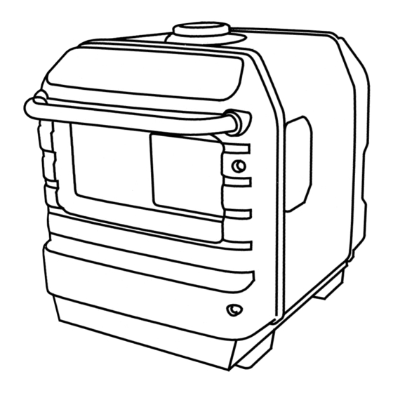
CONTROLS & FEATURES COMPONENT & CONTROL LOCATIONS Use the two illustrations on these pages to locate and identify the most frequently used controls. OUTPUT INDICATOR OVERLOAD INDICATOR OIL ALERT INDICATOR ENGINE SWITCH CHOKE KNOB FUEL VALVE LEVER VOLTMETER OUTPUT SWITCH GROUND TERMINAL DC OUTPUT... - Page 15 MUFFLER OIL FILLER CAP/ DIPSTICK OIL DRAIN PLUG OIL MAINTENANCE COVER MAINTENANCE COVER FUEL TANK CAP STARTER GRIP CONTROL & FEATURES SPARK PLUG CAP FRONT HANDLE DC VOLTAGE SELECTOR SWITCH AIR CLEANER FUEL GAUGE REAR HANDLE...
-
Page 16: Controls
CONTROL & FEATURES CONTROLS DC Voltage Selector Switch The DC voltage selector switch is used to select generator DC voltage; either 36 V or 48 V. Select the same voltage as the battery voltage of the UPS battery string. To operate the DC voltage selector switch, make sure the engine is off, then open the maintenance cover. -
Page 17: Choke Knob
CONTROLS Choke Knob The choke knob opens and closes the choke valve in the carburetor. The CLOSED position enriches the fuel mixture for starting a cold engine. The OPEN position provides the correct fuel mixture for operation after starting, and for restarting a warm engine. -
Page 18: Recoil Starter
CONTROL & FEATURES Recoil Starter Pulling the starter grip operates the recoil starter to crank the engine for starting. Do not allow the starter grip to snap back against the engine. Return it gently to prevent damage to the starter. Do not let the starter rope rub against the generator body or the rope will wear out... -
Page 19: Features
FEATURES Ground Terminal The ground terminal is connected to the frame of the generator and the metal non-current-carrying parts of the generator. Before using the ground terminal, consult a qualified electrician, electrical inspector or local agency having jurisdiction for local codes or ordinances that apply to the intended use of the generator. -
Page 20: Output Indicator
CONTROL & FEATURES Output Indicator The output indicator (green) is illuminated when the generator is operating normally. It indicates that the generator is producing electrical power at the DC output coupler. OUTPUT INDICATOR (GREEN) Overload Indicator The overload indicator (red) will go steady ON if the generator is overloaded, the converter becomes overheated or there is a short circuit in the connected UPS battery string. -
Page 21: Oil Alert Indicator
Oil Alert Indicator The Oil Alert system is designed to prevent engine damage caused by an insufficient amount of oil in the crankcase. Before the oil level in the crankcase can fall below a safe limit, the Oil Alert indicator comes on and the Oil Alert system automatically will stop the engine (the engine switch will remain in the ON position). -
Page 22: Before Operation
BEFORE OPERATION ARE YOU READY TO GET STARTED? Your safety is your responsibility. A little time spent in preparation will significantly reduce your risk of injury. Knowledge Read and understand this manual. Know what the controls do and how to operate them. Familiarize yourself with the generator and its operation before you begin using it. -
Page 23: Check The Engine
BEFORE OPERATION Check the Engine Check the oil level (see page ). A low oil level will cause the Oil Alert system to shut down the engine. Check the air filter (see page ). A dirty air filter will restrict air flow to the carburetor, reducing engine and generator performance. -
Page 24: Operation
OPERATION SAFE OPERATING PRECAUTIONS Before operating the generator for the first time, please review the GENERATOR SAFETY section and the chapter titled BEFORE OPERATION . For your safety, avoid starting or operating the generator in an enclosed area such as a garage. Your generator’s exhaust contains poisonous carbon monoxide gas which can collect rapidly in an enclosed area and cause illness or death. -
Page 25: Starting The Engine/Dc Operation
STARTING THE ENGINE/DC OPERATION Select the same voltage as the battery voltage of UPS. Open the maintenance cover. Select the DC voltage selector switch; either 36 V or 48 V. Close the maintenance cover. Connect the power cord of UPS to the DC output coupler. When the UPS battery string is connected to the generator, the back light in the voltmeter is turned on and indicates the battery string voltage. - Page 26 OPERATION Turn the fuel valve lever to the ON position. Pull the choke knob to the CLOSED position to start a cold engine. Leave the choke knob in the OPEN position to restart a warm engine. FUEL VALVE LEVER CHOKE KNOB CLOSED...
- Page 27 Turn the engine switch to the ON position. Pull the starter grip lightly until you feel resistance, then pull briskly. Pull the starter grip as shown in the picture at the right. Do not allow the starter grip to snap back against the engine.
-
Page 28: Forced Output
OPERATION Forced Output The forced output function should only be used by personnel who are knowledgeable regarding UPS battery string operation. Follow the instructions in the UPS battery owner’s manual. The DC voltage selector switch must be set equal to the voltage of the UPS battery string. - Page 29 Operation: Verify that the overload indicator (red) is flashing. Press the output switch for 5 seconds, the overload indicator (red) will go off. Release your finger from the switch. If step 3 is not carried out within 5 seconds, the overload indicator (red) will start to flash again.
-
Page 30: Stopping The Engine
OPERATION STOPPING THE ENGINE To stop the engine in an emergency, simply turn the engine switch to the OFF position. Under normal conditions, use the following procedure. Push the output switch. Output is off, but engine is operating. Turn the engine switch to the OFF position. - Page 31 Turn the fuel valve lever to the OFF position. Remove the power cord coupler from the DC output coupler. DC OUTPUT COUPLER POWER CORD COUPLER OPERATION FUEL VALVE LEVER...
-
Page 32: Servicing Your Generator
SERVICING YOUR GENERATOR THE IMPORTANCE OF MAINTENANCE Good maintenance is essential for safe, economical, and trouble-free operation. It will also help reduce air pollution. To help you properly care for your generator, the following pages include a maintenance schedule, routine inspection procedures, and simple maintenance procedures using basic hand tools. -
Page 33: Maintenance Safety
MAINTENANCE SAFETY Some of the most important safety precautions follow. However, we cannot warn you of every conceivable hazard that can arise in performing maintenance. Only you can decide whether or not you should perform a given task. Failure to properly follow maintenance instructions and precautions can cause you to be seriously hurt or killed. -
Page 34: Maintenance Schedule
SERVICING YOUR GENERATOR MAINTENANCE SCHEDULE REGULAR SERVICE PERIOD (3) ITEM Perform at every indicated month or operating hour interval, whichever comes first. Engine oil Air filter Sediment cup Spark plug Spark arrester Valve clearance Combustion chamber Fuel tank and filter Fuel line *... -
Page 35: Refueling
REFUELING With the engine stopped, check the fuel level. Refill the tank if the fuel level is low. Gasoline is highly flammable and explosive. You can be burned or seriously injured when handling fuel. Stop the engine and keep heat, sparks, and flame away. -
Page 36: Fuel Recommendations
SERVICING YOUR GENERATOR FUEL RECOMMENDATIONS Use unleaded gasoline with a pump octane rating of 86 or higher. This engine is certified to operate on unleaded gasoline. Unleaded gasoline produces fewer engine and spark plug deposits and extends exhaust system life. Never use stale or contaminated gasoline or an oil/gasoline mixture. -
Page 37: Engine Oil Level Check
ENGINE OIL LEVEL CHECK Check the engine oil level with the generator on a level surface and the engine stopped. Open the oil maintenance cover. Remove the oil filler cap/dipstick and wipe it clean. Insert and remove the dipstick without screwing it into the filler neck. Check the oil level shown on the dipstick. -
Page 38: Engine Oil Change
SERVICING YOUR GENERATOR ENGINE OIL CHANGE Drain the oil while the engine is warm to assure rapid and complete draining. Open and remove the oil maintenance cover. Place a suitable container below the engine to catch the used oil, then remove the oil filler cap/dipstick, drain plug and sealing washer. Allow the used oil to drain completely, then reinstall the drain plug and sealing washer. -
Page 39: Engine Oil Recommendations
SERVICING YOUR GENERATOR ENGINE OIL RECOMMENDATIONS Oil is a major factor affecting performance and service life. Use 4-stroke automotive detergent oil. SAE 10W 30 is recommended for general use. Other viscosities − shown in the chart may be used when the average temperature in your area is within the recommended range. -
Page 40: Air Cleaner Service
SERVICING YOUR GENERATOR AIR CLEANER SERVICE Open the maintenance cover. Unsnap the air cleaner cover clips, remove the air cleaner cover. Foam air filter: Remove the foam air filter from the air cleaner cover. Check the foam air filter to be sure it is clean and in good condition. - Page 41 Paper air filter: If the paper air filter is dirty, replace it with a new one. Do not clean the paper air filter. Reinstall the air cleaner cover. Close and latch the maintenance cover. Operating the engine without an air filter, or with a damaged air filter, will allow dirt to enter the engine, causing rapid engine wear.
-
Page 42: Foam Air Filter Cleaning
SERVICING YOUR GENERATOR FOAM AIR FILTER CLEANING A dirty foam air filter will restrict air flow to the carburetor, reducing engine performance. If you operate the generator in very dusty areas, clean the foam air filter more frequently than specified in the Maintenance Schedule. -
Page 43: Sediment Cup Cleaning
SEDIMENT CUP CLEANING Turn the fuel valve lever to the OFF position. Open the maintenance cover. Remove the air cleaner cover, foam and paper air filter (see page Disconnect the breather hose from the air cleaner base. Remove the 6 mm bolt and two 6 mm nuts, and remove the air cleaner base. - Page 44 SERVICING YOUR GENERATOR Remove the sediment cup by turning it counterclockwise. Gasoline is highly flammable and explosive. You can be burned or seriously injured when handling fuel. Wash the sediment cup, O-ring and filter in nonflammable solvent, and dry them thoroughly. Reinstall the filter, new O-ring, and sediment cup.
-
Page 45: Spark Plug Service
SPARK PLUG SERVICE Recommended spark plugs: Incorrect spark plugs can cause engine damage. Open the maintenance cover. Loosen the cover screw and remove the spark plug inspection cover. SPARK PLUG INSPECTION COVER COVER SCREW Disconnect the spark plug cap, and remove any dirt from around the spark plug area. - Page 46 SERVICING YOUR GENERATOR Inspect the spark plug. Replace it if the electrodes are worn or if the insulator is cracked, chipped or fouled. Measure the spark plug electrode gap with a wire-type feeler gauge. Correct the gap, if necessary, by carefully bending the side electrode.
-
Page 47: Spark Arrester Service
SPARK ARRESTER SERVICE The spark arrester must be serviced every 100 hours to keep it functioning as designed. If the engine has been running, the muffler will be very hot. Allow the muffler to cool before servicing the spark arrester. Remove the four 6 mm cap nuts, and remove the rear cover. - Page 48 SERVICING YOUR GENERATOR Remove the three 5 mm bolts, and remove the exhaust tail pipe and the spark arrester. 5 mm BOLTS Use a brush to remove carbon deposits from the spark arrester screen. Be careful to avoid damaging the screen. Inspect the spark arrester screen for breaks, holes or tears.
- Page 49 Install the lower muffler protector, the rear under plate and the rear handle in the reverse order of removal. Install the lower muffler protector inside the hook securely. REAR HANDLE Install the upper muffler protector and the rear cover in the reverse order of removal.
-
Page 50: Storage
STORAGE STORAGE PREPARATION Proper storage preparation is essential for keeping your generator trouble-free and looking good. The following steps will help to keep rust and corrosion from impairing your generator’s function and appearance, and will make the engine easier to start when you use the generator again. - Page 51 Adding a Gasoline Stabilizer to Extend Fuel Storage Life When adding a gasoline stabilizer, fill the fuel tank with fresh gasoline. If only partially filled, air in the tank will promote fuel deterioration during storage. If you keep a container of gasoline for refueling, be sure that it contains only fresh gasoline.
- Page 52 STORAGE Draining the Fuel Tank and Carburetor Gasoline is highly flammable and explosive. You can be burned or seriously injured when handling fuel. Stop the engine and keep heat, sparks, and flame away. Handle fuel only outdoors. Wipe up spills immediately. Open the maintenance cover.
-
Page 53: Engine Preparation
Engine Preparation Change the engine oil (see page Remove the spark plug (see page Pour a tablespoon (5 Pull the starter rope several times to distribute the oil in the cylinder. Reinstall the spark plug. Slowly pull the starter grip until resistance is felt. At this point, the piston is coming up on its compression stroke and both the intake and exhaust valves are closed. -
Page 54: Storage Precautions
STORAGE STORAGE PRECAUTIONS If your generator will be stored with gasoline in the fuel tank and carburetor, it is important to reduce the hazard of gasoline vapor ignition. Select a well-ventilated storage area away from any appliance that operates with a flame, such as a furnace, water heater, or clothes dryer. Also avoid any area with a spark-producing electric motor, or where power tools are operated. -
Page 55: Transporting
TRANSPORTING If the generator has been running, allow the engine to cool for at least 15 minutes before loading the generator on the transport vehicle. A hot engine and exhaust system can burn you and can ignite some materials. Keep the generator level when transporting to reduce the possibility of fuel leakage. -
Page 56: Taking Care Of Unexpected Problems
TAKING CARE OF UNEXPECTED PROBLEMS ENGINE PROBLEMS Engine Will Not Start Check control positions. Check fuel. Check engine oil level. Remove and inspect spark plug. Take generator to an authorized Alphagen servicing dealer, or refer to shop manual. Possible Cause Fuel valve lever OFF. - Page 57 TAKING CARE OF UNEXPECTED PROBLEMS Engine Lacks Power Check air filter. Check fuel. Take generator to an authorized Alphagen servicing dealer, or refer to shop manual. Possible Cause Air filter clogged. Bad fuel; generator stored without treating or draining gasoline, or refueled with bad gasoline.
-
Page 58: Generator Problems
TAKING CARE OF UNEXPECTED PROBLEMS GENERATOR PROBLEMS No Power at the DC Output Coupler Check output and overload indicator. Check UPS battery string voltage requirement. Check the power cord. Take generator to an authorized Alphagen servicing dealer, or refer to shop manual. - Page 59 TAKING CARE OF UNEXPECTED PROBLEMS Forced Output Function Cannot Be Used Check overload indicator. Check the voltmeter. Restart the engine. Take generator to an authorized Alphagen servicing dealer, or refer to shop manual. Possible Cause Overload indicator is OFF. The UPS battery voltage is not in the tolerance level for the forced...
-
Page 60: Technical & Consumer Information
TECHNICAL & CONSUMER INFORMATION TECHNICAL INFORMATION Serial Number Location FRAME SERIAL NUMBER Record the frame serial number in the space below. You will need this serial number when ordering parts, and when making technical or warranty inquiries. Frame serial number: Date purchased:... -
Page 61: Carburetor Modification For High Altitude Operation
TECHNICAL & CONSUMER INFORMATION Carburetor Modification for High Altitude Operation At high altitude, the standard carburetor air-fuel mixture will be too rich. Performance will decrease, and fuel consumption will increase. A very rich mixture will also foul the spark plug and cause hard starting. Operation at an altitude that differs from that at which this engine was certified, for extended periods of time, may increase emissions. -
Page 62: Oxygenated Fuels
TECHNICAL & CONSUMER INFORMATION Oxygenated Fuels Some conventional gasolines are being blended with alcohol or an ether compound. These gasolines are collectively referred to as oxygenated fuels. To meet clean air standards, some areas of the United States and Canada use oxygenated fuels to help reduce emissions. -
Page 63: Emission Control System Information
TECHNICAL & CONSUMER INFORMATION Emission Control System Information Source of Emissions The combustion process produces carbon monoxide, oxides of nitrogen, and hydrocarbons. Control of hydrocarbons and oxides of nitrogen is very important because, under certain conditions, they react to form photochemical smog when subjected to sunlight. Carbon monoxide does not react in the same way, but it is toxic. - Page 64 TECHNICAL & CONSUMER INFORMATION Problems That May Affect Emissions If you are aware of any of the following symptoms, have your engine inspected and repaired by your authorized Alphagen servicing dealer. Hard starting or stalling after starting. Rough idle. Misfiring or backfiring under load. Afterburning (backfiring).
-
Page 65: Air Index
TECHNICAL & CONSUMER INFORMATION Air Index An Air Index Information hang tag/label is applied to engines certified to an emission durability time period in accordance with the requirements of the California Air Resources Board. The bar graph is intended to provide you, our customer, the ability to compare the emissions performance of available engines. -
Page 66: Specifications
− − IN: 0.15 0.02 mm ± EX: 0.20 0.02 mm ± No other adjustments needed. DCX3000 EAMJ 25.8 in (655 mm) 17.5 in (445 mm) 21.9 in (555 mm) 117 lbs (53 kg) GX200 12.0 cu-in (196 cm ) ×... -
Page 67: Wiring Diagram
TECHNICAL & CONSUMER INFORMATION Wiring Diagram... -
Page 68: Consumer Information
TECHNICAL & CONSUMER INFORMATION CONSUMER INFORMATION Publications These publications will give you additional information for maintaining and repairing your generator. You may order them from your Alphagen dealer. Shop Manual This manual covers complete maintenance and overhaul procedures. It is intended to be used by a skilled technician. Parts Catalog This manual provides complete, illustrated parts lists. -
Page 69: Customer Service Information
TECHNICAL & CONSUMER INFORMATION Customer Service Information For general product information and customer service 7:00AM to 5:00PM Pacific Time To obtain complete Technical Support 7:00AM to 5:00PM Pacific Time For after-hours Emergency Support 7 days per week, 24 hours a day Alpha Technologies 3767 Alpha Way Bellingham, WA 98226... -
Page 70: Index
INDEX AIR CLEANER SERVICE Air index ARE YOU READY TO GET STARTED ? BEFORE OPERATION Carbon Monoxide Hazards Carburetor Modification for High Altitude Operation Check the engine Choke knob Cleaning COMPONENT & CONTROL LOCATIONS CONSUMER INFORMATION CONTROLS CONTROLS & FEATURES Customer Service information DC Operation DC Output Coupler... - Page 71 EcoThrottle System Electric Shock Hazards Emission Control System Information Engine Preparation ENGINE OIL CHANGE ENGINE OIL LEVEL CHECK ENGINE OIL RECOMMENDATIONS ENGINE PROBLEMS Engine Switch FEATURES Fire and Burn Hazards FOAM AIR FILTER CLEANING Forced Output Fuel Fuel Gauge FUEL RECOMMENDATIONS Fuel Valve Lever GENERATOR PROBLEMS GENERATOR SAFETY...
- Page 72 INDEX IMPORTANT SAFETY INFORMATION INDEX IS YOUR GENERATOR READY TO GO ? Knowledge MAINTENANCE SAFETY MAINTENANCE SCHEDULE Oil Alert Indicator OPERATION Operator Responsibility Output Indicator Output Switch Overload Indicator Oxygenated Fuels Publications QUICK REFERENCE INFORMATION Recoil Starter REFUELING Refuel With Care REMOVAL FROM STORAGE .Inside back cover...
- Page 73 SAFE OPERATING PRECAUTIONS SAFETY LABEL LOCATIONS Safety Precautions SEDIMENT CUP CLEANING Serial Number Location SERVICING YOUR GENERATOR Specifications SPARK ARRESTER SERVICE SPARK PLUG SERVICE STARTING THE ENGINE STOPPING THE ENGINE STORAGE STORAGE PRECAUTIONS STORAGE PREPARATION TAKING CARE OF UNEXPECTED PROBLEMS TECHNICAL INFORMATION TECHNICAL &...
- Page 74 MEMO...
-
Page 75: Quick Reference Information
QUICK REFERENCE INFORMATION Fuel Type Spark Plug Type Electrode Gap Maintenance Before each use First 20 hours Subsequent Unleaded gasoline with a pump octane rating of 86 or higher NGK: BPR5ES (NGK) DENSO: W16EPR-U (DENSO) 0.028 0.031 in (0.70 0.80 mm) −...
Need help?
Do you have a question about the DCX3000 and is the answer not in the manual?
Questions and answers