
Related Manuals for AlphaGen DCX3000


Summary of Contents for AlphaGen DCX3000
-
Page 1: Operation Manual
DCX3000 Portable Generator Operation Manual 3.0kW, 36/48V, DC Portable Generator Effective: September 2006 Alpha Technologies... - Page 2 Power Alpha Technologies ®...
- Page 3 AlphaGen DCX3000 3.0kW, 36/48V DC Portable Generator Operation Manual 041-028-B0-003, Rev. C Effective Date: September 2006 Copyright© 2006 Alpha Technologies, Inc. member of The Group NOTE: Photographs contained in this manual are for illustrative purposes only. These photographs may not match your installation.
-
Page 4: Table Of Contents
Table of Contents Safety Notes .......................... 6 Introduction ......................... 8 Specifi cations......................9 Battery Cable Connections ..................10 Enclosures with Generator Access Door ............10 Enclosures without Generator Access Door ...........11 Grounding ...................... 16 Starting the Engine ....................18 Engine Shut-Down and Cable Removal ..............20 Long-term Storage .................. - Page 5 List of Figures Fig. 1-1, DCX3000 Overview ....................8 Fig. 1-2, Basic Block Diagram ....................8 Fig. 3-1, Generator Access Door and Battery Pack Adapter Cable ........10 Fig. 3-2, Enclosure without Generator Access Door.............11 Fig. 3-3, Alligator Clamp-style Connection ................12 Fig.
-
Page 6: Safety Notes
Safety Notes Review the drawings and illustrations contained in this manual before proceeding. If there are any questions regarding the safe installation or operation of this product, contact Alpha Technologies or the nearest Alpha representative. Save this document for future reference. To reduce the risk of injury or death, and to ensure the continued safe operation of this product, the following symbols have been placed throughout this manual. -
Page 7: General Safety Information
General Safety Information • The manufacturer cannot anticipate every circumstance that may involve a hazard, therefore, these warnings are not all inclusive. • Do not use the generator or any of its parts as a step. • Generator must be properly grounded. •... -
Page 8: Introduction
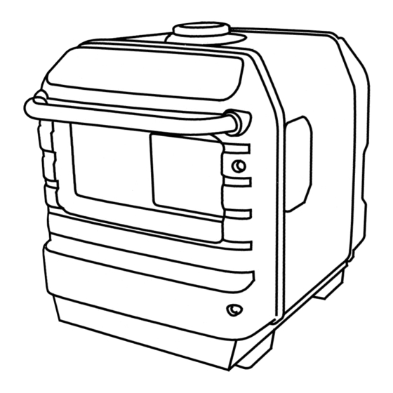
1.0 Introduction The Alphagen DCX3000 portable DC generator supplies DC power to a power node battery bus during AC line interruptions. Upon loss of commercial AC power, the existing battery strings supply the power supply inverters. After some interval of battery discharge, the operator deploys the portable generator at the site to supply power to the DC bus. -
Page 9: Specifi Cations
2.0 Specifi cations Honda GX 200 6.5 hp, air-cooled, OHV, single cylinder, manual recoil starting, manual choke ngine Fuel/Fuel Tank Unleaded gasoline/3.5 gallon metal tank with level gauge Rated Power 2800W continuous, 3000W maximum Alternator Permanent magnet, brushless, bearingless Output Voltage 36V: 39.5VDC, nominal at generator output connector Dual range selector 48V: 52.5VDC, nominal at generator output connector... -
Page 10: Battery Cable Connections
3.0 Battery Cable Connections Enclosures with Generator Access Door Tools and Materials Needed: • Portable Generator Battery Cable Kit • DC Multimeter Procedure: 1. Open the enclosure’s battery compartment and locate the battery pack connections for the positive and negative battery cables leading to the power supply. 2. -
Page 11: Enclosures Without Generator Access Door
Battery Cable Connections, continued Enclosures without Generator Access Door Tools and Materials Needed: • 2.5" Punch Tool Kit for Enclosures (Alpha P/N 745-131-20) • 2.5" Enclosure Upgrade Kit (Alpha P/N 745-131-21) • Electric drill • #7 Drill bit (.2010”) or #9 drill bit (.1960”) •... -
Page 12: Fig. 3-3, Alligator Clamp-Style Connection
Battery Cable Connections, continued Extension Cable Set, 50’ P/N 875-324-21 30’ P/N 875-324-20 10’ P/N 875-324-22 Fuse Alligator Clamp-style Battery Pack Adapter Cable, P/N 874-946-20 Black Ensure clamps lay fl at against batteries, facing inward Fig. 3-3, Alligator Clamp-style Connection 041-028-B0-003, Rev. -
Page 13: Fig. 3-4, Ring Lug-Style Connection
Battery Cable Connections, continued Extension Cable Set, 50’ P/N 875-324-21 30’ P/N 875-324-20 10’ P/N 875-324-22 Fuse Ring Lug-style Battery Pack Adapter Cable, P/N 874-946-21 Black Cable rings connect directly to the battery terminals Fig. 3-4, Ring Lug-style Connection 041-028-B0-003, Rev. C... -
Page 14: Fig. 3-5, Novus-Style Connection
Battery Cable Connections, continued Circuit Breaker must be CLOSED OUTPUTS GENERATOR BREAKER BYPAS CONVENIENCE FROM XT1 EXT GENERATOR HEATING PADS Novus Power Panel BLACK Novus-style Battery Pack Adapter Cable P/N 875-324-23 Extension Cable Set, 50’ P/N 875-324-21 30’ P/N 875-324-20 10’... -
Page 15: Fig. 3-6, Y-Style Connection
Battery Cable Connections, continued Y-style Battery Pack Adapter Cable P/N 874-946-22 Extension Cable Set, 50’ P/N 875-324-21 30’ P/N 875-324-20 10’ P/N 875-324-22 Fuse Fig. 3-6, Y-style Connection 041-028-B0-003, Rev. C... -
Page 16: Grounding
Battery Cable Connections, continued Grounding Tools and Materials Needed: #8AWG copper ground wire and clamps Procedure: 1. Read and thoroughly understand the Engine Owner’s Manual before operating this equipment. 2. Before starting the generator, follow all instructions outlined in the BEFORE OPERATION section of the Engine Owner’s Manual. -
Page 17: Fig. 3-8, Overview Of Pwe Installation
Battery Cable Connections, continued To prevent injury, the generator MUST share a common ground with the enclosure service entrance. Power Meter Ground Stake Ground Wire Fig. 3-8, Overview of PWE Installation 041-028-B0-003, Rev. C... -
Page 18: Starting The Engine
4.0 Starting the Engine Prior to starting the generator, review the Safety Information on page 6 of this manual. Set the generator on a fl at, level surface, free of standing or running water, or combustible materials. Operating the generator at an angle of more than 15 degrees may result in the oil level dropping below a safe level. -
Page 19: Table 4-1, Battery Voltage And Output Indications
Starting the Engine, continued Voltage Select Output Indicator Overload Alarm Battery Voltage Forced Output Switch Position (Green LED) (Red LED) Not Available 0V to 2V Not Available FLASHING ENABLED 2V to 27V FLASHING ENABLED Not Available 27V to 42V FLASHING ENABLED FLASHING Not Available... -
Page 20: Engine Shut-Down And Cable Removal
5.0 Engine Shut-Down and Cable Removal WARNING! Engine block and muffl er become extremely hot during normal operation. Procedure: 1. Press the OUTPUT SW to remove voltage from the battery pack. 2. Turn the ENGINE SW OFF. 3. Turn the FUEL VALVE OFF. Disconnect the battery pack adaptor from the extension cable. -
Page 21: Fuse Replacement
Engine Shut-Down and Cable Removal, continued Fuse Replacement Tools and Materials Needed: • 10mm and 8mm socket • Ratchet handle • Torque wrench • Replacement fuse: Alpha P/N 460-273-10, Hinode Electric Co. P/N 350GH-80 Procedure: 1. Set the ENGINE SW to OFF. Disconnect the extension cable from the DC Out jack. -
Page 22: Maintenance Record
6.0 Maintenance Record Use the following form to log maintenance and repair of your DCX3000. Maintenance Record (Refer to engine owners manual for service requirements and intervals) Model Number Serial Number Hour Date Action Initials Meter 041-028-B0-003, Rev. C... - Page 24 Power Alpha Technologies ® Alpha Technologies 3767 Alpha Way Bellingham, WA 98226 Tel: +1 360 647 2360 Fax: +1 360 671 4936 Web: www.alpha.com Alpha Technologies Ltd. 4084 McConnell Court Burnaby, BC, V5A 3N7 CANADA Tel: +1 604 430 1476 Fax: +1 604 430 8908 Alpha Technologies Europe Ltd.
Need help?
Do you have a question about the DCX3000 and is the answer not in the manual?
Questions and answers