Table of Contents
Advertisement
Quick Links
Download this manual
See also:
User Manual
Advertisement
Table of Contents

Related Manuals for ASROCK Mini Series


Summary of Contents for ASROCK Mini Series
-
Page 1: User Manual
Mini Series User Manual Version 1.0 Published July 2013 Copyright©2013 ASRock INC. All rights reserved. -
Page 2: Copyright Notice
ASRock. ASRock assumes no responsibility for any errors or omissions that may appear in this manual. With respect to the contents of this manual, ASRock does not provide warranty of any kind, either expressed or implied, including but not limited to the implied warran- ties or conditions of merchantability or fitness for a particular purpose. -
Page 3: Safety Instructions
Safety instructions Your system is designed and tested to meet the latest standards of safety for infor- mation technology equipment. However, to ensure your safety, it is important that you read the fol lowing safety instructions. Setting up your system •... -
Page 4: Installation Notices
Safety cautions and warnings Optical Drive Safety Information Optical drives sold with this system contains a CLASS 1 LASER PRODUCT. CAUTION: Invisible laser radiation when open. Do not stare into beam or view directly with optical instruments. WARNING: Making adjustments or performing procedures other than those specified in the user’s manual may result in hazardous laser exposure. -
Page 5: Table Of Contents
7.1.2 Installation ..........25 7.2 Symantec Norton AntiVirus Software free bundle (Trial version) ............28 7.3 ASRock APP Charger .......... 29 7.4 CyberLink MediaEspresso 6.5 (Trial version) ..30 7.5 ASRock XFast RAM ..........31 7.6 ASRock XFast USB ..........34 7.7 ASRock XFast LAN .......... - Page 6 8 UEFI SETUP UTILITY ......... 43 8.1 Introduction ............43 8.1.1 UEFI Menu Bar ........... 43 8.1.2 Navigation Keys ......... 44 8.2 Main Screen ............45 8.3 OC Tweaker Screen ..........46 8.4 Advanced Screen ..........48 8.4.1 CPU Configuration ........49 8.4.2 North Bridge Configuration ......
-
Page 7: Introduction
Chapter 1 Introduction Thank you for purchasing ASRock Mini Series, a reliable product pro- duced under ASRock’s consistently stringent quality control. It delivers excellent performance with robust design conforming to ASRock’s commit- ment to quality and endurance. Because the hardware specifications and the BIOS software might be updated, the content of this manual will be subject to change without notice. -
Page 8: Specifications
Bluetooth 4.0/3.0 HS class II Controller MCE Remote Controller Power 65W/19V Adapter Dimension 195mm(W) x 70mm(H) x 186mm(L) Volume 2.5L Free bundle software: 1. Symantec Norton AntiVirus Software (Trial version) 2. CyberLink MediaEspresso 6.5 (trial version) 3. ASRock XFast LAN, XFast RAM, XFast USB... - Page 9 WARNING Please realize that there is a certain risk involved with over- clocking, including adjusting the setting in the BIOS, applying Untied Overclocking Technology, or using third-party overclock- ing tools. Overclocking may affect your system’s stability, or even cause damage to the components and devices of your system.
-
Page 10: Motherboard Layout
1.3 Motherboard Layout DDR3_A1 DDR3_A2 1. SATA 3.0 connector: For the HDD’s SATA data cable 2. Heatsink 3. Fan connector 4. Fan connector 5. Memory sockets 6. Infrared module header 7. CPU Fan 8. Mini-PCI Express expansion slot: For the WiFi module 9. - Page 11 1. SATA and Power Connections Connect to ODD SATA & Power Connections Connect to SATA Connector (4) Connect to HDD Connect to ATX5V Power Connector (3) Connect to SATA Connector (1) 2. Fan Connection...
-
Page 12: Rear Panel
1.4 Rear Panel S O N Y HDMI D-Sub 13. DC-In jack 14. Optical S/PDIF Out port 15. Mic In (Pink): Microphone 16. Front L/R Out (Lime): Stereo speakers or headphones 17. HDMI connector 18. VGA connector 19. DVI connector 20. -
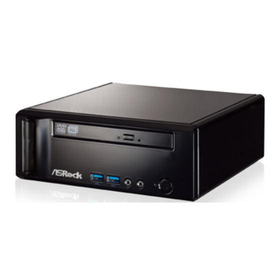
Page 13: System Chassis
1.5 System Chassis 28 27 25. Optical Disc Drive 26. Power ON/OFF button with status indicator 27. Drive activity indicator 28. Headphone port 29. Microphone port 30. USB 3.0 ports: USB devices 31. Infrared receiver... -
Page 14: Remote Controller
1.6 Remote Controller Some remote controller functions listed above are only available with the relative hardware equipments. If the hardware equipments you adopt are not compatible with the system, you are not allowed to use these functions. This product is designed to meet MCE standards. -
Page 15: Quick Installation
Chapter 2 Quick Installation 1. Connecting USB Devices to the USB2.0 Ports. 2. Connecting a VGA Monitor to the VGA Port. 3. Connecting the Network with the RJ-45 LAN Port. 4. Connecting an HDMI Device to the HDMI Port. - Page 16 5. Connecting a DVI Device to the DVI Port. 6. Connecting an External Audio Device. (Line In Port for 2/4/6 Channel; Rear Port for 8 Channel) 7. Connecting Stereo Speakers or Headphones. (Front L/R Out Port) 8. Connecting a Microphone. (Mic In Port) 9.
- Page 17 10. Connecting Side Speakers. (Side Port for 4/6/8 Channel) 11. Connecting an Optical Device to the Optical S/PDIF Out Port. 12. Connecting Power to the DC-In Jack. 13. Powering on the System. 14. Connecting Headphones / Microphones / USB3.0 Devices...
-
Page 18: Reinstalling The Odd/Hdd
Chapter 3 Reinstalling the ODD/HDD 1. Remove the cover screws on the rear panel. (For safety reasons, please ensure that the power cord is disconnected before opening the case. 2. Slide the side cover toward the rear panel and pull the side cover upwards. - Page 19 4. Pull the ODD / HDD rack backwards and take it out from the bay. 5. Unscrew the screws from the side of the ODD / HDD rack, and change your required ODD / HDD. 6. Refer to the steps above to place the new ODD / HDD to the chassis. Replace the side cover and fasten the screws.
-
Page 20: Installing The Second Hdd
Chapter 4 Installing the Second HDD 1. Please follow steps 1 to 4 above, and remove the ODD and the first HDD in advance. Then fasten the screws of the second HDD to the rack. 2. Place the first HDD to the rack and fasten the screws from both sides. 3. - Page 21 4. Connect the SATA and power cables to the ODD and the bottom HDD. 5. Connect the other SATA and power cables to SATA3_1 and J1 connectors on the motherboard. 6. Connect the other end to the top HDD. 7. Replace the side cover and fasten the screws.
-
Page 22: Dual Monitor
Chapter 5 Dual Monitor With the internal VGA output which supports DVI-D, HDMI and D-Sub, you can enjoy dual monitor on your ASRock Mini series HTPC. ASRock Mini series HTPC also provides independent display controllers for DVI-D, HDMI and D-Sub to support dual VGA output so that DVI-D, HDMI and D-Sub can drive the same or different display contents simulta- neously. -
Page 23: Driver Installation
Chapter 6 Driver Installation To install the drivers to your system, please insert the support CD to your optical drive first. Then, the drivers compatible to your system can be auto- detected and listed on the support CD driver page. Please follow the order from top to bottom to install those required drivers. -
Page 24: Utility Menu
Chapter 7 Utility Menu The utility menu shows the applications and other software that this product supports. 7.1 Instant Boot 7.1.1 Introduction Instant Boot, a user-friendly tool that allows you to turn on your PC in just a few seconds, provides a much more efficient way to save energy, time, money, and improves the system’s running speed *. -
Page 25: Installation
7.1.2 Installation Please read the procedures below carefully before you install Instant Boot. A. Install Instant Boot driver from ASRock’s support CD, or you may click the following link to get the latest utility and BIOS: http://www.asrock.com/feature/InstantBoot/download.asp ® B. Execute the Instant Boot installation program under Windows Please follow the instructions on Instant Boot’s setup page. - Page 26 Click “Install” to begin installing Instant Boot driver. e. Click “Finish” to complete and exit the setup. C. After the installation is completed, you will find an ASRock Instant ® Boot icon on Windows desktop. D. Double click ASRock Instant Boot’s icon on the desktop, then Instant...
- Page 27 E. On Instant Boot’s main menu, you can choose “Fast Mode”, “Regular Mode” or “Disable Instant Boot”. After that, please click “Apply” to save your changes. Please notice that you need to keep the AC power on if you select “Fast Mode”. F.
-
Page 28: Symantec Norton Antivirus Software Free Bundle (Trial Version)
7.2 Symantec Norton AntiVirus Software free bundle (Trial version) Protect your PC with Norton Internet Security, the fastest virus, spyware, Internet protection. Norton Internet Security can stop online identity theft, viruses, spyware, bots and more. Stop attacks before they get on your PC, deliver clear threat and performance explanations, identify unsafe web sites right in your search results, and use intelligence-driven Norton Insight Network for faster, fewer, shorter scans. -
Page 29: Asrock App Charger
If you desire a faster, less restricted way of charging your Apple devices, such as an iPhone/iPad/iPod Touch, ASRock has prepared a wonderful solution for you - ASRock App Charger. Simply by installing the App Charger driver makes your iPhone charge much quicker from your computer and up to 40% faster than before. -
Page 30: Cyberlink Mediaespresso 6.5 (Trial Version)
7.4 CyberLink MediaEspresso 6.5 (Trial version) ® CyberLink MediaEspresso 6.5 trial now supports Intel Quick Sync Video hardware transcoding and is optimized for second generation Core i7, i5, and i3 processors to accelerated conversion of all your favorite media files for your favorite portable players. Now you can easily display your favorite movies, songs and photos on iPhone, iPad, PSP, XBox, Youtube, Facebook etc. -
Page 31: Asrock Xfast Ram
7.5 XFast RAM ASRock XFast RAM is a new function that is included in ASRock Extreme Tuning Utility (AXTU). It fully utilizes the memory space that cannot be ® used under Windows 32-bit OS. ASRock XFast RAM shortens the loading time of previously visited websites, making web surfing faster than ever. - Page 32 XFast RAM Settings You may find the XFast RAM setup page in the left panel of ASRock Ex- treme Tuning utility. First select the desired drive and disk size to create a virtual drive. ® To access more than 4GB of RAM in Windows 32-bit OS, please leave PAE mode set to ON.
- Page 33 drive instead of the hard disk drive to accelerate performance speed. Lastly, select the files that are supposed to go in the virtual drive to speed up the system’s performance. Such as temporary files created by com- puter programs when they cannot allocate enough memory for its tasks. Or internet cache files including html, images, Cascading Style Sheets and JavaScript scripts from IE, Firefox and Google Chrome.
-
Page 34: Asrock Xfast Usb
7.6 ASRock XFast USB Not only does ASRock XFast USB boost up the performance of USB 2.0 storage devices, but also USB 3.0 devices. Users may experience up to five times faster USB data transfer speed! - Page 35 XFast USB UI overview Hide the XFast USB window Select your language Select a connected USB Click to activate/ storage device deactivate Turbo mode Click to safely remove Select Normal mode or the USB hard drive Turbo mode Plug in your USB storage device and XFast USB automatically sets it to Turbo mode!
- Page 36 D. Then, you will see ASRock XFast USB user interface as below. You can also double-click the “XFast USB” icon to show this interface. Please choose “Turbo” to enable ASRock XFast USB Technology. The detailed information of your USB device can also be found in this user interface.
-
Page 37: Asrock Xfast Lan
7.7 ASRock XFast LAN ASRock XFast LAN provides several special features for faster internet access. For example, LAN Application Prioritization allows you to configure your application’s priority ideally or add new programs to the priority list. Traffic Shaping helps you watch Youtube HD videos and download files simultaneously without hiccups. - Page 38 XFast LAN UI overview The default status window Low Latency Mode switch arrow down = currently Open slot on (if needed) configuration arrow up = always on Download activity display dialog no arrow = off Open Current TX shaping Connections window indicator Ping time in ms Show/hide slot...
- Page 39 bottom right and selecting Open windows. Window settings Users may configure the skin and effects of the user interface. Make the keyboard LEDs display Traffic Shaping information. Or display the XFast LAN status window on a Logitech gamer keyboard instead of Win- dows desktop.
- Page 40 Adding a new application and changing its priority Click search and choose a new program you wish to add. You can also type in a short description for the program. Set the priority for the program and TX Limit then click Add to confirm. Hit the switch button to change configurations or Delete to remove the ap- plication from the priority list.
-
Page 41: Other Unique Features
7.8 Other Unique Features ASRock Instant Flash ASRock Instant Flash is a BIOS flash utility embedded in Flash ROM. This convenient BIOS update tool allows you to update system BIOS without entering operating ® systems first like MS-DOS or Windows . - Page 42 PC. Just simply enable this function; the PC will enter the UEFI directly after you restart. ASRock Good Night LED ASRock Good Night LED technology can offer you a bet- ter environment by extinguishing the unessential LED. By enabling Good Night LED in BIOS, the Power / HDD / LAN LED will be switched off when system is on.
-
Page 43: Uefi Setup Utility
Chapter 8: UEFI SETUP UTILITY 8.1 Introduction This section explains how to use the UEFI SETUP UTILITY to configure your system. The UEFI chip on the motherboard stores the UEFI SETUP UTILITY. You may run the UEFI SETUP UTILITY when you start up the computer. -
Page 44: Navigation Keys
8.1.2 Navigation Keys Use < > key or < > key to choose among the selections on the menu bar, and use < > key or < > key to move the cursor up or down to select items, then press <Enter> to get into the sub screen. You can also use the mouse to click your required item. -
Page 45: Main Screen
8.2 Main Screen When you enter the UEFI SETUP UTILITY, the Main screen will appear and display the system overview. -
Page 46: Oc Tweaker Screen
8.3 OC Tweaker Screen In the OC Tweaker screen, you can set up overclocking features. DRAM Timing Configuration DRAM Frequency If [Auto] is selected, the motherboard will detect the memory module(s) in- serted and assigns appropriate frequency automatically. Power Down Mode Use this to enable or disable DDR power down mode. - Page 47 Use this to change CAS# Latency (tCL) Auto/Manual settings. The default is [Auto]. DRAM tRCD Use this to change RAS# to CAS# Delay (tRCD) Auto/Manual set- tings. The default is [Auto]. DRAM tRP Use this to change Row Precharge Time (tRP) Auto/Manual set- tings.
-
Page 48: Advanced Screen
8.4 Advanced Screen In this section, you may set the configurations for the following items: CPU Configuration, Nouth Bridge Configuration, South Bridge Configuration, Storage Configuration, Super IO Configuration, ACPI Configuration and USB Configuration. Setting wrong values in this section may cause the system to malfunction. -
Page 49: Cpu Configuration
8.4.1 CPU Configuration Cool ‘n’ Quiet Use this to enable or disable AMD’s Cool ‘n’ Quiet technology. The default value is [Enabled]. Configuration options: [Enabled] and ® [Disabled]. If you install Windows 7 / Vista and want to enable this function, please set this to [Enabled]. Please note that enabling this may reduce CPU voltage and memory frequency, and lead to system stability or compatibility issues with some memory modules or power supplies. -
Page 50: North Bridge Configuration
8.4.2 North Bridge Configuration Share Memory This allows you to configure share memory. The default value is [Auto]. Onboard HDMI HD Audio This allows you to enable or disable the Onboard HDMI HD Audio. -
Page 51: South Bridge Configuration
8.4.3 South Bridge Configuration Onboard HD Audio Select [Auto], [Enabled] or [Disabled] for the onboard HD Audio. If you select [Auto], the onboard HD Audio will be disabled when a PCI Sound Card is plugged. On/Off Play Use this to enable or disable On/Off Play Technology. The default value is [Enabled]. -
Page 52: Storage Configuration
8.4.4 Storage Configuration SATA Controller Use this to enable or disable the SATA Controller. SATA Mode Use this to select the SATA mode for SATA3_1 port. Configuration options: [IDE Mode] and [AHCI Mode]. The default value is [AHCI Mode]. AHCI (Advanced Host Controller Interface) supports NCQ and other new features that will improve SATA disk performance but IDE mode does not have these advantages. -
Page 53: Super Io Configuration
8.4.5 Super IO Configuration Infrared Port Use this to enable or disable the onboard infrared port. CIR Controller Use this to enable or disable the CIR Controller. -
Page 54: Acpi Configuration
8.4.6 ACPI Configuration Suspend to RAM Use this to select whether to auto-detect or disable Suspend-to- RAM. Select [Auto] to enable if the OS supports it. Check Ready Bit Use this to enable or disable Check Ready Bit. ACPI HPET Table Use this to enable or disable the ACPI HPET Table. - Page 55 Please disable CSM when Fast Boot is enabled. The default value is [Enabled].
-
Page 56: Usb Configuration
8.4.7 USB Configuration Legacy USB Support Use this to select legacy support for USB devices. There are four configuration options: [Enabled], [Auto], [Disabled] and [UEFI Setup Only]. The default value is [Enabled]. Please refer to the descrip- tions below for details of these four options: [Enabled] - Enables support for legacy USB. -
Page 57: Tool
8.5 Tool OMG (Online Management Guard) Administrators are able to establish an internet curfew or restrict internet access at specified times via OMG. You may schedule the starting and ending hours of internet access granted to other us- ers. In order to prevent users from bypassing OMG, guest accounts without permission to modify the system time are required. - Page 58 OS. Please note that you must be running on a DHCP configured computer in order to enable this function. Network Configuration Use this to configure internet connection settings for Internet Flash. User Defaults You are allowed to load and save three user defaults according to your own requirements.
-
Page 59: Hardware Health Event Monitoring Screen
8.6 Hardware Health Event Monitoring Screen This section allows you to monitor the status of the hardware on your sys- tem, including the parameters of the CPU temperature, motherboard tem- perature, fan speed and voltage. CPU Fan 1 Setting This allows you to set CPU fan 1’s speed. The default value is [Au- tomatic Mode]. -
Page 60: Boot Screen
8.7 Boot Screen This section displays the available devices on your system for you to con- figure the boot settings and the boot priority. Fast Boot Fast Boot minimizes your computer’s boot time. Configuration op- tions: [Disabled] - Disable Fast Boot. [Fast]: When selecting “Fast”, it is not allowed to boot from a USB storage device. - Page 61 after boot-up. Full Screen Logo Use this item to enable or disable OEM Logo. The default value is [Enabled]. AddOn ROM Display Use this option to adjust AddOn ROM Display. If you enable the option “Full Screen Logo” but you want to see the AddOn ROM information when the system boots, please select [Enabled].
-
Page 62: Security Screen
8.8 Security Screen In this section you may set or change the supervisor/user password for the system. You may also clear the user password. Secure Boot Use this to enable or disable Secure Boot Control. The default value is [Disabled]. -
Page 63: Exit Screen
8.9 Exit Screen Save Changes and Exit When you select this option the following message, “Save configu- ration changes and exit setup?” will pop out. Select [OK] to save changes and exit the UEFI SETUP UTILITY. Discard Changes and Exit When you select this option the following message, “Discard changes and exit setup?”... -
Page 64: Software Support
Click on a specific item then follow the installation wizard to install it. 9.2.4 Contact Information If you need to contact ASRock or want to know more about ASRock, you are welcome to visit ASRock’s website at http://www.asrock.com; or you may contact your dealer for further information.
Need help?
Do you have a question about the Mini Series and is the answer not in the manual?
Questions and answers