Honda HHT35S Owner's Manual
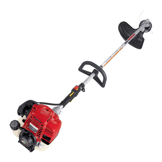
Trimmer/brush cutter
Hide thumbs
Also See for HHT35S:
- Owner's manual (32 pages) ,
- Manual (131 pages) ,
- Owner's manual (32 pages)

Related Manuals for Honda HHT35S


Summary of Contents for Honda HHT35S
- Page 1 Owner's Manual Trimmer/Brush Cutter HHT25S • HHT35S See page 41 for instructions on assembling your Trimmer. © 2002, 2006 American Honda Motor Co., Inc.—All Rights Reserved...
- Page 2 Keep this owner’s manual handy, so you can refer to it at any time. This owner’s manual is considered a permanent part of the trimmer/brush cutter and should remain with the trimmer/brush cutter if resold. The information and specifications included in this publication were in effect at the time of approval for printing.
- Page 3 We want to help you get the best results from your new trimmer/brush cutter and to operate it safely. This manual contains the information on how to do that; please read it carefully.
-
Page 4: A Few Words About Safety
INTRODUCTION A FEW WORDS ABOUT SAFETY Your safety and the safety of others are very important, and using this trimmer/brush cutter safely is an important responsibility. To help you make informed decisions about safety, we have provided operating procedures and other information on labels and in this manual. -
Page 5: Table Of Contents
TRIMMER SAFETY ... 4 IMPORTANT SAFETY INFORMATION ... 4 ATTACHMENTS & MODIFICATIONS... 5 IMPORTANT MESSAGE TO EMPLOYERS ... 5 SAFETY LABEL LOCATIONS... 6 RECOMMENDED CUTTING ATTACHMENTS ... 7 CUTTING-LINE HEADS AND SHIELDS ... 7 BLADES AND SHIELDS ... 8 CUTTING ATTACHMENT APPLICATIONS... 9 CONTROLS &... -
Page 6: Trimmer Safety
TRIMMER SAFETY IMPORTANT SAFETY INFORMATION The Honda HHT25S and HHT35S trimmer/brush cutters are designed to cut grass, weeds, brush, and/or wood if equipped with an appropriate cutting attachment. Other uses can result in injury to the operator or damage to the trimmer and other property. -
Page 7: Attachments & Modifications
As an employer, you have special responsibilities to the people who work for you. Before you ask anyone to operate this trimmer/ brush cutter, you need to determine whether the operator is old enough, large enough, and strong enough to safely handle and control the trimmer/ brush cutter. -
Page 8: Safety Label Locations
The labels shown here contain important safety information. Please read them carefully. These labels are considered permanent parts of your trimmer/brush cutter. If a label comes off or becomes hard to read, contact an authorized Honda servicing dealer for a replacement. -
Page 9: Recommended Cutting Attachments
RECOMMENDED CUTTING ATTACHMENTS CUTTING-LINE HEADS AND SHIELDS A cutting-line head containing nylon monofilament line and a debris shield with a cutoff knife is standard equipment. The shield’s cutoff knife automatically removes any excess line that is released from the cutting head. The U-type handlebar trimmers are supplied with two different debris shields. -
Page 10: Blades And Shields
RECOMMENDED CUTTING ATTACHMENTS BLADES AND SHIELDS A variety of blades are available from your Honda trimmer servicing dealer. Always use a debris shield designed for use with a blade when attaching a blade to your trimmer. The blade type debris shield does not have a cutoff knife. Honda U-type handlebar trimmers are supplied with a blade cover surrounding the edge of the blade. -
Page 11: Cutting Attachment Applications
Remove the blade cover in the reverse order of installation. CUTTING ATTACHMENT APPLICATIONS HHT25S HHT35S GRASS AND LIGHT WEEDS THICK WEEDS AND LIGHT BRUSH WOODY BRUSH, SHRUBS, SAPLINGS Your Honda trimmer servicing dealer has cutting attachments that have been designed and approved for your trimmer and are covered by warranty. -
Page 12: Controls & Equipment
CONTROLS & EQUIPMENT COMPONENT & CONTROL LOCATIONS LOOP TYPE HANDLE CUTTING-LINE HEAD GEAR CASE LOOP HANDLE DEBRIS SHIELD WITH CUTOFF KNIFE DRIVE CABLE FRAME PIPE IGNITION SWITCH THROTTLE TRIGGER U-TYPE HANDLEBAR (supplied with a cutting-line head, a saw blade, and two debris shields) SAW BLADE CUTTING-LINE HEAD DEBRIS SHIELD... -
Page 13: Controls
CONTROLS The location and operation of the controls are similar on both the HHT25S and HHT35S models. Choke Lever The choke lever opens and closes the choke valve. The CLOSED position enriches the fuel mixture for starting a cold engine. - Page 14 CONTROLS & EQUIPMENT Throttle Set Button The throttle set button is used to hold the throttle trigger at the fast idle position for starting. Do not allow the cutting line or blade to contact any obstruction when starting the engine with the throttle set button engaged.
-
Page 15: Equipment
CONTROLS & EQUIPMENT EQUIPMENT FULL SHOULDER HARNESS (U-type handlebar) The Honda HHT25S and HHT35S trimmer/brush cutters are supplied with a shoulder harness and safety glasses. Refer to page 14 for a description of other equipment and protective clothing you will need. -
Page 16: Before Operation
BEFORE OPERATION ARE YOU READY TO OPERATE THE TRIMMER? Your safety is your responsibility. A little time spent in preparation will significantly reduce your risk of injury. Knowledge Read and understand this manual. Know what the controls do and how to operate them. Familiarize yourself with the trimmer and its operation before you begin to use it. -
Page 17: Is Your Trimmer Ready To Go
IS YOUR TRIMMER READY TO GO? For your safety, and to maximize the service life of your equipment, it is very important to take a few moments before you operate the trimmer to check its condition. Be sure to take care of any problem you find, or have your servicing dealer correct it, before you operate the trimmer. -
Page 18: Are Your Shoulder Harness And Trimmer Correctly Adjusted
BEFORE OPERATION ARE YOUR SHOULDER HARNESS AND TRIMMER CORRECTLY ADJUSTED? Adjusting the Harness Adjust the harness so the quick-release latch is at your right hip, as shown. QUICK-RELEASE LATCH FULL SHOULDER HARNESS QUICK-RELEASE LATCH SINGLE-STRAP SHOULDER HARNESS Balancing the Trimmer on the Shoulder Harness Hang the trimmer on the harness hook, and see how it balances. -
Page 19: Operation
SAFE OPERATING PRECAUTIONS Before operating the trimmer for the first time, please review the IMPORTANT SAFETY INFORMATION chapter on page 4 and BEFORE OPERATION chapter starting on page 14. Even if you have operated other trimmers, take time to become familiar with the operation of this trimmer’s controls and handling. - Page 20 OPERATION 5. Set the trimmer on the ground, resting on the debris shield and the fuel tank guard. Do not allow the cutting-line or blade to contact any obstruction. Always rest the trimmer on the ground for starting, rather than holding it in the operating position.
-
Page 21: Stopping The Engine
STOPPING THE ENGINE 1. Release the throttle trigger. 2. Move the ignition switch to the STOP (O) position. Wait for the cutting line head or blade to stop before allowing the end of the trimmer to contact anything. WARNING The blade will continue to spin briefly after the engine has stopped or the throttle trigger is released. - Page 22 OPERATION Throttle Operation Pull the throttle trigger toward the grip to increase engine speed and start the cutting attachment rotation. The trimmer has the greatest cutting force at maximum engine speed. Release the throttle trigger to reduce engine speed. At idle, the cutting attachment should coast to a stop.
-
Page 23: Safe Operating Practices
Using Blades Refer to the chart on page 9 for appropriate blade applications. If using a blade on a Honda trimmer equipped with a loop handle, also install the optional Honda conversion kit that includes a full shoulder harness, a barrier bar, and a debris shield for blades. -
Page 24: Operating Tips
Blades on Honda HHT25S and HHT35S trimmers rotate counterclockwise, as viewed from the operator’s position. Therefore, the left side of the blade is moving toward you. With these trimmers, sawing with the left side of a brush blade will give you better control and less risk of kickback, though it will throw the sawdust toward you. - Page 25 OPERATION Trimming and Edging Use nylon line for cutting against a hard surface. Work from an angle where debris that strikes the DEBRIS hard surface will ricochet away from you. Avoid contact with wires, wire fences, metal rods, etc. Overlapping a wire will cause the nylon line to wrap around the wire and break off.
-
Page 26: Servicing Your Trimmer
SERVICING YOUR TRIMMER THE IMPORTANCE OF MAINTENANCE Good maintenance is essential for safe, economical, and trouble-free operation. It will also help reduce air pollution. WARNING Improperly maintaining this trimmer, or failure to correct a problem before operation, can cause a malfunction in which you can be seriously hurt or killed. -
Page 27: Maintenance Schedule
MAINTENANCE SCHEDULE Perform at every ITEM indicated interval. Check Engine oil Change Check Air filter Clean Throttle cable Check Cutting attachment Check Debris shield Check Check Nuts, bolts, fasteners (Retighten if necessary) Shoulder harness quick-release Check Drive cable Check-Lubricate Idle speed Check-Adjust Valve clearance Check-Adjust... -
Page 28: Engine
SERVICING YOUR TRIMMER ENGINE Engine Oil Level Check Check the engine oil level before each use, or every 10 hours if operated continuously. Rest the trimmer on a level surface, with the engine stopped and in an upright position. 1. Remove the filler cap/dipstick and wipe it clean. - Page 29 Engine Oil Recommendations Oil is a major factor affecting performance and service life. Use 4-stroke automotive detergent oil. SAE 10W-30 is recommended for all temperatures within the recommended operating range for these trimmers. The recommended operating range extends from 23°F (-5°C) to 104°F (40°C). The SAE oil viscosity and service classification are on the API label on the oil container.
- Page 30 SERVICING YOUR TRIMMER Throttle Cable Inspection Verify the throttle trigger operates smoothly and the throttle cable is undamaged. If there is visible damage, or if the throttle trigger does not operate smoothly, have your authorized Honda servicing dealer replace the throttle cable. Check the free play at the end of the throttle cable.
-
Page 31: Cutting Attachments
Using non-Honda line may result in increased noise levels. For original, factory-installed Honda cutting-line heads, use only nylon monofilament line in the line sizes shown below. Line Size 0.095" Model HHT25S HHT35S See page 59 for replacement parts information. 0.105"... - Page 32 SERVICING YOUR TRIMMER Manual Cutting-Line Head 1. Clean any mud, dirt, debris, etc. from the area around the trimmer head; otherwise, it will be more difficult to service. 2. Rotate the left-hand threaded knob in the direction of the arrow and remove the knob. Remove the spring and spool from the housing then remove any remaining old line from the spool.
- Page 33 5. When you have about 6 inches (150 mm) of line remaining, press the lines into the two notches on the bottom of the spool. This will hold the lines on the spool for reassembly. 6. Feed both line ends through the metal eyelets in the housing.
- Page 34 SERVICING YOUR TRIMMER Semi-Matic (Bump-Feed) Cutting-Line Head 1. Clean any mud, dirt, debris, etc., from around the trimmer head area; otherwise, it will be more difficult to service. 2. Locate the half-round locking hole on the spool. 3. It may be necessary to lightly rotate the spool in the direction of the arrow about an 1/8 turn until the spool stops.
- Page 35 7. Wind both lines tightly and evenly from side to side ignoring the ridge. Feed the line while turning the spool in the direction of the arrow. Do not allow the line to get twisted. It is important to prevent the two lines from getting twisting over each other.
- Page 36 SERVICING YOUR TRIMMER Removal and Installation This section shows you how to remove and install either style trimmer head from your trimmer. 1. Insert the tip of a 4 mm hex wrench, or equiv- alent, fully into the gear case hole. 2.
- Page 37 Blade Blade Inspection Always wear gloves when working around the blade. Before each use, check the blade for wear and damage, and check the tightness of the blade lock nut. Examine the entire head area, including the debris shield, and clear or clean it free from dirt, debris, loose string, wire, or any other foreign materials.
- Page 38 SERVICING YOUR TRIMMER 1. Install the protective plastic cover that came with the blade. 2. Insert a commercially available 4 mm hex tool or equivalent fully into the gear case hole. 3. Turn the blade until you feel the tool drop into the hole in cover plate/spacer A.
- Page 39 Spark Plug Service Recommended spark plug: CMR5HSB (NGK) NOTICE Incorrect spark plugs can cause engine damage. 1. Remove the 5 x 12 mm hex bolt and top cover. 2. Disconnect the spark plug cap, and remove any dirt from around the spark plug area. 3.
- Page 40 SERVICING YOUR TRIMMER Spark Arrester Service The spark arrester must be serviced every 100 hours to keep it functioning as designed. If the engine has been running, the muffler will be very hot. Allow the muffler to cool before servicing the spark arrester.
-
Page 41: Fuel System
Refueling Fuel tank capacities: HHT25S: 0.13 US gal/16.9 fl oz (0.50 ) HHT35S: 0.17 US gal/22.0 fl oz (0.65 ) Check the fuel level by looking through the translucent fuel tank. If the fuel level is low, refuel in a well-ventilated area with the engine stopped. - Page 42 SERVICING YOUR TRIMMER Fuel Filter and Fuel Tank Cleaning 1. Remove the fuel tank cap and empty the fuel tank into an approved gasoline container. Use a funnel to avoid spill- ing gasoline. 2. Pull the fuel filter out through the fuel filler neck by hooking the black fuel supply tube with a piece of wire, such as a partly straightened paper clip.
-
Page 43: Assembly
After assembly and before operation, review the Safe Operating Precautions on page 17. IMPORTANCE OF PROPER ASSEMBLY Proper assembly is essential to operator safety and the reliability of the machine. Any error or oversight made by the person assembling and servicing a machine can result in faulty operation, damage to the machine, or injury to the operator. -
Page 44: Unpacking
• • • • • OWNER'S MANUAL HHT25S•HHT35S Trimmer/Brush Cutter HHT25S • HHT35S See page 41 for instructions on assembling your Trimmer. U- TYPE HANDLEBAR 10W-30 Genuine Honda Oil Specially formulated and blended for Honda engines. Meets or exceeds American Petroleum Institute SJ standards. -
Page 45: Trimmer Assembly
TRIMMER ASSEMBLY U-Shaped Handlebar Installation 1. Remove the four 5 x 28 mm bolt/washers and handlebar holder A. 2. Set the U-shaped handle into handlebar holder B with the throttle trigger facing to the right. 3. Adjust the handlebar position as shown. 4. - Page 46 ASSEMBLY Saw Blade The U-type handlebar models are shipped with a manual nylon cutting-line head installed on the trimmer. If the saw blade is needed, move the ignition switch to the STOP (O) position and disconnect the spark plug cap from the spark plug. Wear protective gloves when working around the cutting-line head and saw blade.
- Page 47 Saw Blade Installation 1. Insert a 4 mm hex wrench or equivalent into the gear case hole to prevent the output shaft from turning. 2. Install cover plate/spacer A onto the output shaft as shown. 3. With the blade cover installed on the blade, install the blade by aligning the center of the blade with the shoulder on cover plate/ spacer A.
-
Page 48: Blade Cover Removal
ASSEMBLY BLADE COVER REMOVAL 1. Turn the blade cover slowly until the cover latch is clear of the debris shield. Unfasten the latch by lifting the tab off the post. 2. Pull the post end away from the blade and set it on top of the blade as shown. 3. -
Page 49: Engine Oil
ENGINE OIL The trimmer is shipped WITHOUT OIL in the engine. 1. Place the trimmer on a level surface then remove the oil filler cap/dipstick. 2. Slowly add the recommended oil (included in the box) to the bottom edge of the oil filler opening. -
Page 50: Storage
STORAGE STORAGE PREPARATION Proper storage preparation is essential to keep your trimmer trouble free and looking good. The following steps will help to keep rust and corrosion from impairing your trimmer's function and appearance, and will make the engine easier to start when you use the trimmer again. -
Page 51: Storage Precautions
Adding Fuel Stabilizer to Extend Fuel Storage Life When adding a fuel stabilizer, fill the fuel tank with fresh gasoline. If only partially filled, air in the tank will promote fuel deterioration during storage. If you keep a container of gasoline for refueling, be sure that it contains only fresh gasoline. -
Page 52: Transporting
TRANSPORTING BEFORE LOADING If the engine has been running, allow it to cool for at least 15 minutes before loading the trimmer on the transport vehicle. A hot engine and exhaust system can burn you and can ignite some materials. Always turn the ignition switch to the STOP (O) position. -
Page 53: Taking Care Of Unexpected Problems
TAKING CARE OF UNEXPECTED PROBLEMS Engine Will Not Start Possible Cause Ignition switch is in the STOP (O) position. Choke is not in the CLOSED position (cold engine). Move the choke to the CLOSED position. Out of fuel. Bad fuel, trimmer stored without treating or draining gasoline, refueled with bad gasoline. - Page 54 TAKING CARE OF UNEXPECTED PROBLEMS Blade or Cutting-line Head Won’t Turn Possible Cause Worn or broken clutch, broken drive cable, worn or broken gear case parts. Excessive Vibration Possible Cause Loose cutting-line head or blade nut. Cutting-line is not wound properly or has unequal line lengths.
-
Page 55: Technical & Consumer Information
TECHNICAL & CONSUMER INFORMATION TECHNICAL INFORMATION This chapter contains important information about serial number locations, high altitude operation, oxygenated fuels, and emissions control systems. Serial Number Locations There are two serial numbers, one for the trimmer and one for the engine. Record these numbers in the space provided. - Page 56 TECHNICAL & CONSUMER INFORMATION Oxygenated Fuels Some conventional gasolines are being blended with alcohol or an ether compound. These gasolines are collectively referred to as oxygenated fuels. To meet clean air standards, some areas of the USA and Canada use oxygenated fuels to help reduce emissions. If you use an oxygenated fuel, be sure it is unleaded and meets the minimum octane rating requirement.
-
Page 57: Emission Control System
EMISSION CONTROL SYSTEM Source of Emissions The combustion process produces carbon monoxide, oxides of nitrogen, and hydrocarbons. Control of hydrocarbons and oxides of nitrogen is very important because, under certain conditions, they react to form photochemical smog when subjected to sunlight. Carbon monoxide does not react in the same way, but it is toxic. - Page 58 Descriptive Term Moderate Intermediate Extended The Air Index Information hang tag/label must remain on the trimmer/brush cutter until it is sold. Remove the hang tag before operating the trimmer/brush cutter. Applicable to Emissions Durability Period 50 hours (0–65 cc) 125 hours (greater than 65 cc) 125 hours (0–65 cc)
-
Page 59: Specifications
HHT35SLTAT HHT35SUKAT • • optional • optional optional HHT35S 73.8 in (1875 mm) 73.8 in (1875 mm) 75.0 in (1905 mm) 12.8 in (325 mm) 23.6 in (600 mm) 10.2 in (260 mm) 15.9 in (405 mm) 14.8 lb. (6.7 kg) 15.4 lb. - Page 60 Ball bearings, helical cut gears, no shims required 2.18 in (55.2 mm) 4,200 ± 200 rpm Square female HHT35S GX35 2.2 cu in (35.8 cc) 1.5 x 1.2 in (39 x 30 mm) 1.6 hp (1.2 kW) at 7,000 rpm 1.4 ft-lbs (1.9 N•m) at 5,500 rpm...
-
Page 61: Consumer Information
Customer Service Information Honda Power Equipment dealership personnel are trained professionals. They should be able to answer any question you may have. If you encounter a problem that your dealer does not solve to your satisfaction, please discuss it with the dealership's management. - Page 62 You must take the Honda Power Equipment product, accessory, replacement part, apparel or the power equipment on which the accessory or replacement part is installed, and proof of purchase, at your expense, to any Honda Power Equipment dealer in the United States, Puerto Rico, or the U.S. Virgin Islands who is authorized to sell that product, during the dealer’s normal business hours.
- Page 63 You must take the Honda Power Equipment accessory, replacement part, apparel or the power equipment on which the accessory or replacement part is installed, and proof of purchase, at your expense, to any Honda Power Equipment dealer in the United States, Puerto Rico, or the U.S. Virgin Islands who is authorized to service that product, during the dealer's normal business hours.
- Page 64 To Obtain Warranty Service: You must take your Honda Power Equipment engine or the product on which it is installed, along with your warranty registration card or other proof of original purchase date, at your expense, to any Honda Power Equipment dealer who is authorized by Honda to sell and service that Honda product during his normal business hours.
-
Page 65: Index
Accessories warranty ... 61 Air filter Check ... 27 Cleaning ... 27 Air index ... 56 Assembly ... 41 Loose parts ... 42 Trimmer assembly ... 43 Unpacking ... 42 Before operation ... 14 Blade Inspection ... 35 Removal/installation ... 35 Usage ... - Page 66 INDEX Maintenance Air filter ...27 Engine oil ...26 Fuel system ...39 Idle speed ...25 Importance ...24 Safety ...24 Schedule ...25 Spark plug ...37 Throttle cable ...28 Oil, engine Changing ...26 Level check ...26 Recommendations ...27 Operating the trimmer ...19 Brush clearing ...23 Scything ...22 Slopes ...23 Tips ...22...
-
Page 67: Quick Reference Information
QUICK REFERENCE INFORMATION Fuel Type Engine oil Type Spark plug Type Before each use Maintenance First 10 hours Subsequent Unleaded gasoline with a pump octane rating of 86 or higher (page 39) SAE 10W-30, API SJ or later (page 27) NGK: CMR5H Check engine oil (page 26) Check air filter (page 27) - Page 68 POM53509B 31VL3D00 IPC XXXX.2006.01 Printed on Printed in U.S.A. 00X31-VL3-D000 Recycled Paper...
Need help?
Do you have a question about the HHT35S and is the answer not in the manual?
Questions and answers