Table of Contents
Advertisement
TREADMILL
SERVICE MANUAL
ClubTrack
ClubTrack Plus
HR ClubTrack
HR ClubTrack Plus
Medtrack CR60
MedTrack SR60
®
377-833
33387- 5 Rev New
Advertisement
Table of Contents

Related Manuals for Quinton ClubTrack


Summary of Contents for Quinton ClubTrack
-
Page 1: Service Manual
TREADMILL SERVICE MANUAL ClubTrack ClubTrack Plus HR ClubTrack HR ClubTrack Plus MedTrack CR60 MedTrack SR60 ® 377-833 33387- 5 Rev New... - Page 2 Service Manual .quinton.com isit Quinton on the World Wide Web at NTERNAT ONAL SALES atin America & Asia-Pacific Telephone 425/402-2000 Fax 425/402-2001 Europe/Hoofddorp, The Netherlands Telephone 31-23-5672400 Fax 31-23-5672410...
- Page 4 Appendix C, art Numbers . he manual is designed for Quinton-authorized service personnel with proper training. here are no user-serviceable parts in the treadmills. Any attempt by non-Quinton-trained personnel to service the treadmill may void the warranty.
-
Page 5: Table Of Contents
Contents reface Overview lubTrack ......1-1 MedTrack ......1-1 onfiguration Plate . - Page 6 roubleshooting ™ Repair/Replacement and Calibration ontents - vi...
- Page 7 reventive Maintenance Safety Requirements Specifications art Numbers ontents - vii...
- Page 8 ontrollers ......-3 Accessories for Heart Rate Monitoring ... -5 ield unctional Tests omplete Field Functional Test .
-
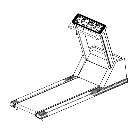
Page 9: Overview
Overview ® ClubTrack ® MedTrack ront of Hood Rear ample Treadmill verview 1-1... - Page 10 Configuration Plate readmills distributed for use outside Circuit Breaker the USA and Canada have detachable Power Cord power cords. Power he circuit breaker on the front of the treadmill hood controls the power to the treadmill. he circuit breaker must be set to the treadmill to run.
-
Page 11: Lubtrack
PCBA 33518-001 Magnet Keypanel 33504 lubTrack and MedTrack SR60/ R60 19296-001 Controller Assy 34506 eart Rate Monitoring LEDs COMPATIBLE COMPATIBLE CLUBTRACK CLUBTRACK PCBA 34296-001 Keypanel 34298 HR lubTrack ontroller with Heart Rate Monitoring Controller Assy 34297 GRADE SPEED POWER UNITS... -
Page 12: Power
SPEED GRADE POWER KM/H UNITS FASTER DOWN SLOWER PREVIOUS MENU MENU QUINTON STOP BELT STOP BELT COOL DOWN START BELT FITNESS EQUIPMENT CBA 35452 Keypanel 35260 R ClubTrack Plus Controller with eart Rate Control Controller Assy 35258 verview 1-4... -
Page 13: Operation
Theory of Operation verview he treadmill consists of three major assemblies: controller, headframe, and deck and roller. ontroller Assembly he controller assembly, which is mechanically attached to the deck, is the user interface. he user presses a key on the controller to enter a command. -
Page 14: Headframe Assembly
eadframe Assembly he headframe assembly includes the drive and grade systems and the electronics that drive these systems. A three-phase AC motor drives the walk belt by supplying torque and speed to the drive pulley through a drive belt. A DC motor drives the front of the treadmill up and down to simulate hills. -
Page 15: Output Displays
Inputs Output Displays Additional Functions ontroller to Treadmill Interface HR lubTrack Plus Interface .quinton.com, eadframe Assembly heory of Operation 2-3... -
Page 16: Input Power Module
nput Power Module he input power module receives line power from the power outlet. When sold for use in the United States and Canada, these treadmills use 115 VAC power. When sold for use in Europe and the United Kingdom, the treadmills use 230 VAC power. Drive Board he treadmill drive board uses line power to develop 300 VDC which is then used to create three-phase power for the drive motor... -
Page 17: Transmitter
eart Rate Monitoring Option he heart rate monitoring function is a wireless system based on existing hardware purchased from POLAR Electro, Inc. he system consists of a transmitter worn on the chest of the user and a receiver mounted inside the controller enclosure. Electronics inside the belt sense electrical energy on the skin during a heart contraction. -
Page 18: Troubleshooting
Troubleshooting he tables and flow charts in this chapter cover the following potential problems: • electrical problems: power, cable connections • electronic problems: PCB, test points, signals • mechanical problems: noise, vibration, grade, speed, belts See Chapter 4 for repair and replacement procedures. Tools hese tools may be needed: •... -
Page 19: Electrical Problems
Electrical Problems se this table when: • The treadmill will not start. • There is no display on the controller. • The treadmill stops unexpectedly. ossible Cause Action ower ower ower Stop Belt roubleshooting 3-2... -
Page 20: Electronic Problems
Electronic Problems Error Codes he treadmill performs an electronic self-test each time that it is powered up. If a problem is detected during either power-up or operation, an error code appears on the display. Note the code recorded by the owner, then reference the table of error codes. If you replace a faulty PCB Assembly, return it to the factory and note the error code. - Page 21 rror Codes (continued) Indication Recommended Action lear Power roubleshooting 3-4...
-
Page 22: Service Mode
Power mode. In service mode, the HR ClubTrack Plus screen lists the tests described below. To perform a test, press the softkey next to the test name, rather than pressing the indicated key combinations. - Page 23 Units P010 Start Course* P011 Resume Course* P012 Cool Down P013 Faster P014 Slower P015 *ClubTrack Plus only Displays top Belt Grade Up Grade Down elect Units Tri-color Display Next tage Up Down Speed/Grade (Open-Loop Mode) roubleshooting 3-6...
- Page 24 The ClubTrack Plus is in both open-loop speed and open-loop grade modes simultaneously. ° Speed p Faster Slower Stop Belt Faster Slower Start Belt Faster Slower Clear Power Grade Faster p Down Stop Belt Faster Slower Down Clear Power HR ClubTrack Plus LCD Display Test ™...
- Page 25 4. Contrast 5. Fluorescent tube brightness test 6. Fonts HR ClubTrack Plus LCD Contrast ™ Set Screen Contrast MENU HR ClubTrack Plus LCD External RS232 Port ™ Test RS232 Port Test transmit out receive in, C—1, C—2, C—3, C—P. CEEE...
-
Page 26: Heart Rate Monitoring Option
ignals on Control Cable Pins Pin No. V D Pin No. DPU ignal (J12) (J1) Heart Rate Monitoring Option he Polar system for heart rate detection and transmission has been time-tested and shown to be accurate and reliable; however, there is a small percentage of people for whom the system will not work. -
Page 27: Mechanical Problems
roblem ossible Cause Remedy o signal on 1. o electrode contact 1. Reposition chest belt, controller re-wet electrodes. 2. Faulty chest belt 2. Test signal using different belt transmitter or a pulse simulator; replace old belt if faulty. 3. Faulty receiver 3. -
Page 28: Drive Belt
roblem ossible Cause Action alk belt slipping 1. Improper walk belt 1. Adjust walk belt tension. tension. 2. Incorrect drive belt 2. Check drive motor tension or drive belt belt. Adjust worn. tensioner or replace drive belt if necessary. alk belt not tracking Belt misaligned or Adjust tracking. - Page 29 Error Code Flow Chart: EPHI and EPLO EPLO EPHI BUS voltage BUS voltage too low is too high Check line Check line voltage. voltage. Have customer get building Too low? maintenance Too high ? to correct voltage problem. CAUTION! Disconnect power and wait for high voltage Is DS3 On?
- Page 30 Error Code Flow Chart: E001 E001 E002 E206 E201 VSD Micropro- Inadvertant Grade Error Microprocessor cessor EPROM/ Reset chip failure RAM failure Verify grounding Enter system is wired Service Replace VSD PCBA correctly and is Mode intact E205 E202 Calibrate Software Speed Error tachometer...
- Page 31 Error Code Flow Chart: E204 E204 Communications Check Ds2 on Error VSD board. CAUTION! Disconnect Verify power and wait communication cable connection for high voltage Ds2 On? at each end. indicator to go off. (Micro 5V) Verify cable pins Clip a volt meter are not bent or Error onto F1 and F2...
- Page 32 Error Code Flow Chart: E203 E203 Error Overcurrent CAUTION! Disconnect Restrict use to power and wait Runner people within Is motor for high voltage outside weight/ specified weight/ turning? indicator to go speed envelope speed envelope. out. Check Reconnect Check for resistance all motor leads disconnected...
- Page 33 Cycle power. CAUTION! Drive motor LED should be Disconnect does not turn on momentarily power and wait then off. for high voltage indicator to go off. Error Procede to code Replace VSD On then off? Error Code Check present? Flow Chart resistance between motor leads.
- Page 34 Treadmill CAUTION! CAUTION! will not Disconnect Disconnect elevate power and wait power and wait for high voltage for high voltage indicator to go off. indicator to go off. Proceed to Error code error code present? Remove grade motor Check limit flow chart.
- Page 35 Repair/Replacement and Calibration The procedures that follow apply to the Hyperdrive ClubTrack, ClubTrack Plus, HR series, and MedTrack rehabilitation treadmills. The PCB assemblies are field-replaceable modules; no procedures are included for component-level repair. This includes: • variable speed drive (VSD) •...
- Page 36 • Be sure treadmill area is free of liquid spills before removing hood. Burns • Allow pulleys, motor, and other treadmill parts to cool sufficiently before touching them. • Unplug the treadmill immediately if signs of overheating occur. Mechanical • Be sure the treadmill power cord is unplugged before working with chain, rack gear, belts, and pulleys.
-
Page 37: Onfiguration Plate
Field Functional Tests You must perform a field functional test after any of the procedures in this chapter are performed. The applicable test is specified after each section in this chapter. Appendix D, Field Functional Tests, contains complete test instructions. The VSD PCBA generates high voltage, which is present whenever DS4 and DS5 are illuminated. - Page 38 5. Remove the three #8 Phillips-head screws located on the back of the hood, above the kick plate 8-32 x 0.375L (35239-183) 6. Grasp the front section of the hood cover at the top and bottom center. Pull and lift to remove while feeding the power cord through the hood cover opening.
- Page 39 ample treadmill with hood cover removed Repair/Replacement and Calibration 4-5...
- Page 40 Replacing the Configuration Plate On North American units, the configuration plate module includes the power cord, which is attached to the plate. On international units, the power cord is removable and is not part of the configuration plate module. 1. Turn off the treadmill circuit breaker, then remove the power cord from the power outlet.
- Page 41 Replacing the Power Cord Hard-wired Cords Tools: Heyco strain relief hand pliers 1. Remove the configuration plate as described above. 2. Use strain relief pliers to squeeze the strain relief on the power cord and pull it free of the configuration plate. 3.
- Page 42 10511-007 Split Ring 01164-003 Flat Washer 13. Remove the four Phillips screws holding the card cage. 14. Remove the VSD/card cage assembly and return it to Quinton. 15. Replace the sil pad for the switching module before installing the new card cage.
- Page 43 Replacing the Tensioner The tensioner may need to be replaced if the poly-V belt slips, if the idler pulley bearing makes noise, or if the tensioner roller is damaged. Do not attempt to disassemble the tensioner. The internal springs are tightly compressed and could cause injury if released.
- Page 44 4. Count how many times the belt rotates in 2 minutes. This should be 62 ± 3 revolutions for all treadmill models. ClubTrack , ClubTrack Plus™, HR ClubTrack™, HR ClubTrack Plus, MedTrack SR60 5. Increase the walk belt speed to 10.0 mph.
-
Page 45: Replacing The Drive Motor
4. Use a ½ -inch socket wrench to remove the end cap from each siderail. 5. Use a ½-inch wrench to remove the four -inch hex bolts that hold the two front-roller retainers to the frame. There are two bolts on each side of the roller assembly. 6. - Page 46 8. Loosen the two set screws on the flywheel/drive pulley and remove. Use a gear puller to pull the flywheel off the motor shaft. Flywheel Assembly 32446-001 - ClubTrack and SR60 32446-003 - CR60 -20 x 0.25L Set Screws (10833-145) Key 01100-002 9.
- Page 47 Replacing the Transformer 1. Turn off the treadmill circuit breaker and remove the power cord from the power outlet. 2. Remove hood as previously described. To prevent high voltage electrical shock: Before working on or around any electrical or mechanical component under the hood, wait at least two minutes from the time you unplug the power cord and be sure the red LEDs on the VSD board are off.
- Page 48 Replacing the Grade Motor A Place a clean sheet of cardboard or a clean rag on the treadmill deck before starting this procedure. Do not elevate the treadmill. 1. Block the treadmill headframe securely with wooden blocks to ensure that the treadmill will not drop when you remove the grade motor.
- Page 49 Grade Motor inion Shaft Chain (30448-001) c. the grade motor chain is aligned correctly. A popping sound in the chain indicates that it is misaligned. Field Functional Test To verify that the treadmill is operating properly, perform Field Test No. 4. See Appendix D, Field Functional Tests, for specific instructions.
- Page 50 Replacing the Grade Potentiometer (POT) 1. Turn off the treadmill circuit breaker and unplug the power cord. Remove the treadmill hood as previously described. Maintain caution throughout the following steps. 2. Release the grade pot setscrew. rade Pot (33171-002) ear (30843-001) Setscrew, 10-32 x 0.25L (10833-144) 3.
- Page 51 4 Black wire: slot 5 2. Verify that the pin has engaged by pulling lightly on the wire. A The slot positions above apply to the ClubTrack, ClubTrack Plus, MedTrack SR60 and MedTrack CR60. Field Functional Test To verify that the treadmill is operating properly, perform Field Test No.
- Page 52 A In order to enter open loop, the grade must be positive. 10. Enter open-loop grade mode: ower a. Press Stop Faster Slower b. Simultaneously press , and on the controller to place the treadmill in service mode. The 0.0 000 0.0. display will read Faster Down...
- Page 53 Install wheel bolts in the proper holes. se top hole for SR60, ClubTrack, ClubTrack Plus, and HR treadmills. se bottom hole for CR60. b. torque the bolts tightly to 46 ft-lb +4 ft-lb.
- Page 54 4. Shake each gear lightly at the top to determine which rack gear is jammed. If there is no play in a rack gear, it is jammed. 5. Remove the rack gear wheels from the rack gear. 6. Remove the upright assembly: Upright Hex-head Hex-head...
- Page 55 16. Calibrate the grade potentiometer (see Calibration Procedures at end of chapter). 17. Test the treadmill grade. Verify that: a. it operates over the full range of 0-15%. b. there is no binding when it moves up or down. c. the grade motor chain is aligned correctly. A popping sound in the chain indicates that it is misaligned.
- Page 56 9. Align the grade sprocket and grade motor sprocket, then tighten the setscrew on the sprocket. 10. Replace the grade motor chain as described. 11. Reassemble the siderails, uprights, and walk belt. 12. Reassemble the rack gear. 13. Adjust the walk belt tension. 14.
- Page 57 7. Operate the treadmill to verify that it reaches the upper and lower grade limits (15% and 0%). Field Functional Test Ensure that the grade will traverse from minimum to maximum and back. Walk Deck Assembly alk belt removed for clarity Replacing the Rollers 1.
- Page 58 Field Functional Test To verify proper operation, perform Field Test No. 3. See Appendix D, Field Functional Tests, for specific instructions. Replacing the Walk Belt or Deck A All instructions are given as if you were exercising on the treadmill. Whenever you install a new walk belt, you should install a new deck or turn over the existing deck (the deck is reversible).
- Page 59 Replacing Compression Mounts Inspect the compression mounts each time you change the walk belt. Replace the mounts if worn. 1. Remove the deck as previously described. 2. Locate and unscrew the compression mounts from the inside of each siderail; there are five long mounts and three short mounts on each siderail.
- Page 60 • after installing a new walk belt. Two adjustment methods are specified. Method 1 is preferred, but two belt tension calipers (Quinton P/N 30113-001) are required. A Both adjustment screws must be completely slack before starting this procedure. Method 1 (Calipers available) 1.
- Page 61 4. Alternately turn the left and right adjustment screws one-half turn until the distance between the tape or pencil marks is 50.203 inch (±0.016) on both sides. Do not overtighten the adjustment screws. Overtightening may damage the walk belt and roller assemblies. 5.
- Page 62 The controller assembly includes the keypanel, the PCBA, and the enclosure that holds them to the treadmill: • The ClubTrack and MedTrack CR60 and SR60 use the enhanced display processor unit (EDPU). • The ClubTrack Plus uses the motivational control unit (MCU).
- Page 63 Polar PCB connector from the controller PCBA. HR ClubTrack Plus treadmills, p/n 00425: a. Disconnect the ribbon cable to the LCD display. Disengage the connector from the cable by sliding the outer connector housing away from the PCB.
- Page 64 Replacing the Fluorescent Tube (HR ClubTrack Plus) 1. Remove the PCBA as described above (Replacing the PCBA). 2. Remove the LCD display from the keypanel and place it face up. 3. Remove the single screw that holds the white plastic fluorescent tube housing together.
- Page 65 Select 4. Press to store the configuration. (For the HR ClubTrack Plus, select the Set Screen Contrast screen and use the contrast up and down buttons to select the optimum contrast. Select Enter to save the value.) Stop Belt 5.
- Page 66 5. Press Clear to reset the display for operation. For HR ClubTrack Plus Treadmills only A In the HR ClubTrack Plus, total time, total distance, and current distance are calculated and saved in the HRC; therefore, any controller replacement restarts the maintenance counters. Total time and distance are saved into non-volatile memory every time the stop belt function is activated.
-
Page 67: Calibration Procedures
Limited Access Switch If the limited access control is on, the treadmill will not operate unless the magnetic key is on the Quinton logo on the controller. Disabling the Limited Access Switch 1. Remove the magnetic key and press Power to turn off the treadmill. -
Page 68: Speed Calibration
5. Lower the grade until the treadmill is level. Measure from the bottom of the siderail to the floor at both the front and rear of the treadmill. Adjust the grade until both measurements are identical. 6. Rotate the grade pot shaft with a screwdriver until the grade display reads . -
Page 69: Preventive Maintenance
Preventive Maintenance efore working on the treadmill or its components, turn off the treadmill circuit breaker and unplug the power cord. High voltages remain under the treadmill hood for a few minutes even after the plug has been removed. Secure long hair, loose clothing, and jewelry before working near the treadmill, particularly near the walking surface or pulleys. - Page 70 . Use a damp sponge to wipe the exteriors and walking belt; do not soak surfaces. Dry all surfaces thoroughly. ever wipe the deck under the belt, even when replacing a • belt. Wiping can ruin the surface. Do not use detergents or cleaning agents on any part of the •...
- Page 71 br sives or chemic ls such s steel wool or lcohol s they c n d m ge the electrodes perm nently. attery The estim ted life of the belt tr nsmitter is 2500 hours of use. For repl cement belt nd for recycling the old tr nsmitter belt, cont ct Pol r Electro t 800/227-1314.
-
Page 72: Safety Requirements
• To avoid potential safety and electrical problems, use parts and accessories that meet Quinton specifications. • This equipment is classified Class I, Type B, ordinary equipment. Not protected against fluid ingress. ated for continuous operation. -
Page 73: Symbol Definitions
ational Fire Protection Association Standard for health care facilities, FPA 99-1993. The leakage currents specified in the standards are for current frequencies up to 1KHz. The AAMI standard test load provides the proper attenuation for frequencies above 1 KHz. This load circuit, illustrated on the previous page, can be found in the referrenced A SI standard. -
Page 74: Specifications
Specifications lubTrack and MedTrack Rehabilitation 00377, 00402) Treadmills 00380, 00390) ERFORMANCE HYSICAL ENVIRONMENT AL pecifications B-1... - Page 75 lubTrack MedTrack ontrollers pecifications B-2...
- Page 76 ulti-function Display pecifications B-3...
- Page 77 lubTrack Plus Treadmills P/N 00382, 00425) ERFORMANCE HYSICAL ENVIRONMENT AL OWER REQUIREMENTS art number Voltage/Hz Current Draw in Min Branch Circuit 00382- Amps Amps FUSE RATINGS pecifications B-4...
- Page 78 lubTrack Plus ontroller P/N 00382) PEED GRADE MULTI-FUNCTION DI PLAY pecifications B-5...
- Page 79 R ClubTrack Plus with eart Rate Control ™ P/N 00425) PEED GRADE LCD DI PLAY pecifications B-6...
- Page 80 ercent vs Angle Relationship for Treadmill Grade Rise θ Rise Rise tan θ = Grade = Grade = tan θ θ = arctan(Grade) (Note: 15% Grade Grade = 0.15) Grade Angle (°) Grade Angle (°) Grade Angle (°) 0.0% 0.00 5.0% 2.86 10.0%...
- Page 81 Part Numbers Final Assemblies PART NUMBER Operator and Service Manuals Part No. Description x signifies the number of the latest revision.) art Numbers C-1...
- Page 82 L CTRICAL Spares DRIV GRAD D CK HARDWAR art Numbers C-2...
- Page 83 34297-001 German 34297-002 French 34297-003 Italian 34297-004 Spanish 34297-005 Japanese 34297-006 Receiver Assy 34295-001 HRM Upgrade Kit Convert ClubTrack to HR ClubTrack with HRM) English 34299-001 German 34299-002 French 34299-003 Italian 34299-004 Spanish 34299-005 Japanese 34299-006 ClubTrack Plus Upgrade Kit Convert ClubTrack to ClubTrack Plus) English, U.S.A.
- Page 84 MedTrack CR60 P/N 00380 & SR60 P/N 00390 ClubTrack Plus P/N 00382 HR ClubTrack Plus with Heart Rate Control P/N 00425 ™ art Numbers C-4...
- Page 85 HR ClubTrack Plus Upgrade Kit ™ hese versions may be available in the future. Accessories for Heart Rate Monitoring To avoid potential safety and electrical problems, use parts and accessories that meet Quinton specifications. art Numbers C-5...
- Page 86 DS5 have gone out. These procedures apply to all Quinton Hyperdrive treadmills (ClubTrack, ClubTrack Plus, HR ClubTrack, HR ClubTrack Plus, MedTrack SR, and MedTrack CR. You may perform the complete test, or only the tests required after repair or replacement of parts as specified in Chapter 4, Repair/ Replacement and Calibration.
- Page 87 Normal display shown on seven segment display (00 150 00). • Tri-color display scrolls INPUT WT. +/- message. HR ClubTrack Plus ™ For the HR ClubTrack Plus, the normal sequence is: • Seven segment displays show all 8s. • LCD screen is all white.
- Page 88 On the ClubTrack Plus, the word Service scrolls across the tri-color display. On the HR ClubTrack Plus, the screen lists the tests described below. To perform a test, press the softkey next to the test name, rather than pressing the indicated key combinations.
- Page 89 (P/N 34295) and re-test. If the problem remains, replace the controller assembly (HR ClubTrack, p/n 34297, HR ClubTrack Plus p/n 35258). D. Test the Grade Operation 1. Remove the hood (refer to Removing Treadmill Hood in Chapter 4, Repair/Replacement and Calibration).
- Page 90 4. Count how many times the belt rotates in two minutes. This should be 62 ± 3 revolutions for all treadmill models. ClubTrack , ClubTrack Plus , HR Treadmills, MedTrack SR60 5. Increase the walk belt speed to 10.0 mph.
- Page 91 ClubTrack , HR ClubTrack™, MedTrack SR60, and MedTrack CR60 Observe the controller displays during initialization. For the ClubTrack, ClubTrack with Heart Rate Monitor, MedTrack SR60, and MedTrack CR60, the normal sequence is: • Seven segment displays show all 8s (888 8888 888).
- Page 92 Normal display is shown on seven segment display (00 150 00). • Tri-color display scrolls INPUT WT. +/- message. HR ClubTrack Plus™ For the HR ClubTrack Plus, the normal sequence is: • Seven segment displays show all 8s. • LCD screen is all white.
- Page 93 ClubTrack , HR ClubTrack™, MedTrack SR60, and MedTrack CR60 Observe the controller displays during initialization. For the ClubTrack, ClubTrack with Heart Rate Monitor, MedTrack SR60, and MedTrack CR60, the normal sequence is: • Seven segment displays show all 8s (888 8888 888).
- Page 94 Normal display is shown on seven segment display (00 150 00). • Tri-color display scrolls INPUT WT. +/- message. HR ClubTrack Plus™ For the HR ClubTrack Plus, the normal sequence is: • Seven segment displays show all 8s. • LCD screen is all white.
- Page 95 4. Count how many times the belt rotates in two minutes. This should be 62 ± 3 revolutions for all treadmill models. ClubTrack , ClubTrack Plus , HR Treadmills, MedTrack SR60 5. Increase the walk belt speed to 10.0 mph.
- Page 96 Field Test No. 4 The following steps must be performed with the treadmill completely assembled, except as noted. With the power cord connected to the correct outlet, turn on the circuit breaker. A. Test the Grade Operation 1. Remove the hood (refer to Removing Treadmill Hood in Chapter 4, Repair/Replacement and Calibration).
- Page 97 ClubTrack , HR ClubTrack™, MedTrack SR60, and MedTrack CR60 Observe the controller displays during initialization. For the ClubTrack, ClubTrack with Heart Rate Monitor, MedTrack SR60, and MedTrack CR60, the normal sequence is: • Seven segment displays show all 8s (888 8888 888).
- Page 98 On the ClubTrack Plus, the word Service scrolls across the tri-color display. On the HR ClubTrack Plus, the screen lists the tests described below. To perform a test, press the softkey next to the test name, rather than pressing the indicated key combinations.
- Page 99 • Perform the LCD display test (pg 3-7). Test the Tri-color Display (ClubTrack Plus only) 1. Press Next Stage+Up+Down until the test begins. Vertical columns on the tri-color display light red, green, and then yellow for one second each. The columns move from left to right until all display LEDs have been tested.
- Page 100 (P/N 34295) and re-test. If the problem remains, replace the controller assembly: HR ClubTrack p/n 34297, HR ClubTrack Plus, p/n 35258. D. Shut Down the Treadmill Turn the circuit breaker off, disconnect the power cord from the outlet, and place the treadmill back in service.
- Page 101 Cage Assembly, Drive CBA 32776 Configuration late 32976 ClubTrack/MedTrack CR60/SR60 Control anel 34238 HR ClubTrack Control anel 33046 ClubTrack lus Control anel, Motivational 34664 HR ClubTrack lus Control anel 33170 Harness Assembly, Limit Switch 32783 Motor, Drive, AC Variable 32359...
- Page 147 Index ndex...
- Page 148 icroprocessor, theory 2-5 odels 1-1 safety require ents A-1 service ode 3-4 service, reco ended 5-1 noise 3-10 speed range 3-6 sy bol definitions A-2 open-loop ode 3-6 operation 1-3 tension 4-25 options 1-4 tensioner 4-8 overview 1-1 theory 2-1 tools 3-1, 4-2 tracking 4-27 P000 3-4...
Need help?
Do you have a question about the ClubTrack and is the answer not in the manual?
Questions and answers