Table of Contents
Advertisement
Advertisement
Table of Contents

Subscribe to Our Youtube Channel
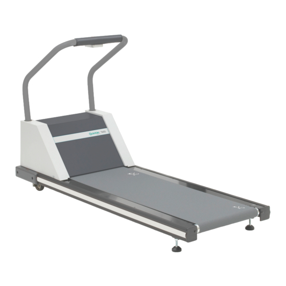
Related Manuals for Quinton TM55


Summary of Contents for Quinton TM55
- Page 1 Cardiac Stress Treadmills Service Manual P/N 042099-001 Rev A...
- Page 2 Quinton Cardiology, Inc. 3303 Monte Villa Parkway Bothell WA 98021-8969 Telephone: 425-402-2000 Fax: 425-402-2001 Toll-free USA: 800-426-0337 E-mail: Service@quinton.com For sales and technical support outside the USA, Quinton customers should contact their local sales and technical support representative. Visit us at www.quinton.com...
- Page 3 Preface This manual contains information for servicing and repairing the Cardiac Stress treadmills, models TM55/TM65 and ST55/ST65, to the module level. The manual covers both domestic and international versions of the treadmills, which can differ in voltage and mandatory emergency stop button.
-
Page 5: Table Of Contents
Contents Introduction Controls ............. . 1-2 Operation. - Page 6 Repair/Replacement and Calibration Electrical Shock ............4-1 Burns .
- Page 7 Vacuuming Under the Treadmill Hood ........5-2 Frequency .
- Page 9 (referred to in this manual as the stress monitor). Four stress treadmill models are available: the TM55/TM65 used with the Quinton Q-Stress Cardiac Stress system and the Burdick Quest Exercise Stress system, and the ST55/ST65 used with other Quinton stress systems such as the Q-4500 and the Q710.
-
Page 10: 1-2 Introduction
Controls Operation The treadmill must be connected to the stress monitor. Except for the emergency stop button, all commands, including walking belt power, speed, grade, and protocol, are entered from the stress monitor. All patient data appears on the stress monitor screen. Power The treadmill must be plugged into a dedicated power outlet. -
Page 11: Theory Of Operation
Theory of Operation Overview The treadmill consists of two subassemblies: the headframe and the deck and roller assembly. The stress monitor, which is attached by cable to the treadmill, functions as the user interface. The user enters all treadmill commands through the stress monitor system with the information appearing on the monitor’s display. -
Page 12: Headframe Assembly
Headframe Assembly The headframe assembly consists of the following components: • Input power module • Drive board assembly • Transformer assembly • Drive motor assembly • Grade motor assembly • Grade system consisting of a pinion shaft, rack gears, feedback potentiometer, and limit switches. - Page 13 A grade potentiometer senses the rack gear movement for the grade system feedback. Limit switches limit the travel of the rack gears in the event of a potentiometer failure or incorrect calibration. Deck and Roller Assembly The deck and roller assembly provides the running surface for the user. This surface consists of a movable and flexible walking belt supported by a semi-rigid platform.
-
Page 15: Troubleshooting
Troubleshooting Diagnosis The tables and flow charts in this chapter cover the following potential problems. Electrical Problems • Power • Cable connections Electronic Problems • AC Drive Module • • Signals Mechanical Problems • Noise • Vibration • Grade • Speed •... -
Page 16: Electrical Problems
off the treadmill circuit breaker, then unplug the treadmill from the power source before removing the hood. Use extreme caution at all times when the hood is removed. Secure loose clothing, jewelry, and long hair before working near treadmill parts. Never place your fingers near rotating parts. -
Page 17: Electronic Problems
Electronic Problems Error Codes Error codes provide the first means of treadmill diagnostics. The treadmill performs an electronic self-test each time that it is powered up. If a problem is detected during either power-up or operation, an error code appears on the stress monitor. Note the code recorded by the owner and reference the table of error codes in the service manual for your stress monitor. -
Page 18: Error Flow Charts
Noise Possible Cause Action Squealing (similar to loose Drive belt loose. Adjust belt tension. automobile fan belt). Replace belt if necessary. Popping during grade Faulty elevation chain Adjust alignment of change. alignment. sprockets. *The type and the rate of bearing noise can help determine which bearing is at fault. - Page 19 Bus Voltage Flow Chart Error Code Flow Chart: EPHI and EPLO Cardiac Stress Treadmills Service Manual Troubleshooting 3-5...
- Page 20 Grade Error Flow Chart Error Code Flow Chart: E201 3-6 Troubleshooting Cardiac Stress Treadmills Service Manual...
- Page 21 Drive Motor Flow Chart Troubleshooting chart for all drive motor related error codes and failures. (Source power and power to drive board on the AC Drive Module established). Error Code Flow Chart: E203 Cardiac Stress Treadmills Service Manual Troubleshooting 3-7...
- Page 22 Communications Link Flow Chart Error Code Flow Chart: E204 3-8 Troubleshooting Cardiac Stress Treadmills Service Manual...
- Page 23 Grade Problems Flow Chart Cardiac Stress Treadmills Service Manual Troubleshooting 3-9...
-
Page 25: Repair/Replacement And Calibration
Repair/Replacement and Calibration The procedures that follow apply to the following treadmills: ST55, ST65, TM55, and TM65. Field repair and replacement is to the modular level. No procedures are included for component-level repair. Electrical Shock Warning! High voltage is present beneath the treadmill hood while the treadmill is connected to a power source. -
Page 26: Mechanical Hazards
Mechanical Hazards Warning! Be sure the treadmill power cord is unplugged before working with chains, rack gear, belt, and pulleys. Secure long hair, loose clothing, and jewelry before working near the treadmill, particularly near walking surface and rotating parts. Before running the treadmill, check for worn parts which could break loose during service or operation. -
Page 27: Removing The Treadmill Hood
Removing the Treadmill Hood 1. If the preamp for the Q-Stress system is attached to the handrail, remove the preamp from the handrail before attempting to remove the hood. 2. Turn off the circuit breaker on the treadmill hood, then unplug the treadmill and the stress monitor from the power outlets. -
Page 28: Replacing The Configuration Plate
♦ Recommended: vacuum the internal components before replacing the hood or applying power. Use caution near the AC Drive Module. Do not vacuum the drive board on the AC Drive Module. Rack Gear Grade Motor AC Drive Module Front Roller Drive Motor Walking Belt Bumper... -
Page 29: Replacing The Power Cord
Replacing the Power Cord Hard-wired Cords on Low Voltage Units 1. Remove the configuration plate as described on previous page. Tools: Heyco strain relief hand 2. Use strain relief pliers to squeeze the strain relief on the power cord pliers and pull it free of the configuration plate. -
Page 30: Bus Recovery System (Brs)
5. Unplug the isolation transformer wires. 6. Unplug the non-isolation transformer wires. 7. Unplug the grade potentiometer wires. Clip the plastic ties around the cage only, not around the headframe. 8. Unplug the limit switch wires. 9. Unplug the power resistor wires. 10. -
Page 31: Replacing The Tensioner
1. Remove the treadmill hood and power as described in “Removing the Treadmill Hood” on page 4-3. 2. Remove the four screws and washers holding the resistors to the headframe. 3. Unplug the resistor wire harness from the AC Drive Module. 4. -
Page 32: Replacing The Poly-V Drive Belt
5. Use either a 15/16 in. open-end wrench or a large adjustable wrench to turn the nut on the tensioner counter-clockwise; put tension on large the poly-V drive belt until the two lines on the tensioner line up (see figure below). Tighten the 3/8 in. bolt to 19 foot-pounds torque. 6. -
Page 33: Replacing The Drive Motor
♦ When replacing the belt, be sure to center it on the pulleys. 14. Assemble the treadmill following steps 3-10 in reverse order. 15. Tension the walking belt as described in “Belt Tension” on page 4-23. 16. Set the tracking as described in “Walking Belt Tracking” on page 4- 17. -
Page 34: Replacing The Transformer
6. Pull the motor off the headframe. Drive Motor Flywheel Setscrew 1/4-20 x 0.25L Tensioner 7. Loosen the two setscrews on the flywheel/drive pulley and remove. Use a gear puller to pull the flywheel off the motor shaft. 8. Reinstall the flywheel onto the motor shaft and loosely tighten the setscrews. -
Page 35: Replacing The Grade Motor
4. Discard the old transformer. Replace with a new one using steps 2 through 4 in reverse order. Transformer 5. If no other service is required, replace the treadmill hood as described in step 9 on page 4-3. Replacing the Grade Motor ♦... - Page 36 3. Disconnect the wire connector on the AC Drive Module. Grade Motor Grade Motor Bolts 1/4-20 x 1.25L Flat Washer Kep Nut Far Side 4. Follow the procedure to remove the grade motor chain (see “Grade Motor Chain” on page 4-13). 5.
-
Page 37: Grade Motor Chain
Grade Motor Chain Pinion Shaft Chain Grade Motor 1. Block the treadmill headframe securely with wooden blocks to ensure that the treadmill will not drop when you remove the grade motor. 2. Use a flathead screwdriver to pop off the C-clip master link on the chain. -
Page 38: Grade Pot Wires
6. Remove the nut holding the grade pot to the bracket. Grade POT Bracket (Step 7) Spur Gear (Step 2) Support Bracket Screws Grade POT 6-32 x 1.25L Flat Washer Nut (Step 6) (Step 5) Setscrew 10-32 x 0.25L 7. Slip the grade pot out of the gear wheel and bracket. 8. -
Page 39: Removing The Rack Gears
Color TM/ST 66 TM/ST55 Red wire: Slot 5 Slot 5 Black wire: Slot 4 Slot 4 Brown or white wire: Slot 3 Slot 3 Blue wire Slots 1 & 2 No blue wire 2. Verify that the pin has engaged by pulling lightly on the wire. 3. -
Page 40: Reassembling The Rack Gears
5. Remove the two hex-head bolts holding the wheels to the rack gears. Note the arrangement of washers used as spacers. Rack Gears (step 11) 3/8-16 x 2.5OL (step 5) 6. Remove the grade pot and bracket assembly (see step 6, “Replacing the Grade Potentiometer (Pot) on page 4-14). -
Page 41: Replacing A Jammed Rack Gear
5. Run the rack gears down past the bottom of the headframe. Hold the limit switches closed to let the rack gear travel beyond its normal lower limit. TM/ST55 TM/ST65 Leftside Limit Switch Locations 6. Check below the headframe to verify that the rack gears are meshing properly. -
Page 42: Replacing The Pinion Shaft
7. Use a 9/16-inch socket wrench to remove the two hex-head bolts that hold each siderail to the headframe. Remove the deck assembly from the headframe. 8. Remove the grade pot bracket and assembly. Remove the four bolts that hold the handrail bracket in place and remove the bracket. 9. - Page 43 2. Restore power to the treadmill, then use the grade motor to turn the pinion shaft until the setscrew on the sprocket is visible. Chain Grade Motor Pinion Shaft 3. Turn off the power and the treadmill circuit breaker, then unplug the treadmill.
-
Page 44: Adjusting The Grade Limit Switches
Adjusting the Grade Limit Switches Grade limit switches prevent the treadmill from exceeding the preset maximum grade. When a roller on the limit switch reaches a trigger in each rack gear, a lever moves inward, opening the switch and stopping the grade motor. -
Page 45: Walking Deck Assembly
Walking Deck Assembly Front (Drive) Roller Deck Fasteners 10-32 x 2.50L Flat Washer, far side Lock Nut, far side Bumper (Removed) End Cap LH, this side Socket Screws 1/4-20 x 1.50L F.W. Retainer Bolts (Step 7) 5/6-18 x 1.25L Setscrew Flat Washer 1/4-20 x 0.625L Hex Nut... -
Page 46: Removing The Deck Assembly From Headframe
10. Pull the walking belt towards the rear of the deck, then slide the rear roller out from between the siderails toward the rear of the treadmill. 11. Replace the rollers and reassemble the treadmill following steps 1-10 in reverse order. 12. -
Page 47: Removing The Deck
4. Adjust the belt tension and tracking. 5. Adjust the rear roller guards. Removing the Deck 1. Remove the deck assembly including front and rear roller assemblies as previously described in “Removing the Deck Assembly from Headframe” on page 4-22. 2. -
Page 48: Method 2: Without Calipers
6. Set the dials of both calipers to zero. 7. Alternately tighten each tension adjustment screw in 0.1% increments until both sides read 0.4%. Be sure that the pointer is exactly on the line increment of the dial for each setting. Caution! Do not overtighten the adjustment screws. -
Page 49: Rear Roller Guard Adjustment
3. Run the treadmill for at least one minute to observe the tracking. Adjustments to belt tracking take some time to become apparent. 4. Repeat steps 2 and 3 as required. Caution! Do not overtighten the adjustment screw. Overtightening can damage the walking belt and assemblies. 5. -
Page 50: Replacing The Emergency Stop Cable
3. Disconnect the two wires attached to the switch. 4. Loosen, but do not remove, the two screws that hold the switch housing and the button assembly together. 5. Twist and separate the button assembly from the switch housing. 6. Reassemble using steps 2 through 5 in reverse order. ♦... -
Page 51: Speed And Grade
5. Loosen the screw that holds the grade pot sprocket to the grade pot. This may require removing, then replacing the two Phillips screws from the pot assembly bracket. 6. Place a flathead screwdriver through the handrail bracket and turn the pot shaft until the stress monitor displays zero grade. -
Page 53: Preventative Maintenance
Preventative Maintenance Warning! Before working on the treadmill or its components, turn off the treadmill circuit breaker and unplug the power cords. High voltages remain under the treadmill hood for a few minutes even after the plug has been removed. Secure long hair, loose clothing, and jewelry before working near the treadmill, particularly near the walking surface or pulleys. -
Page 54: Cleaning The Treadmill Surfaces
Cleaning the Treadmill Surfaces Follow these steps to clean the treadmill after servicing or as required: 1. Elevate the treadmill to maximum height and vacuum the floor under it to prevent excess dust and dirt from interfering with operation. 2. Clean the treadmill exterior with a damp sponge, then dry thoroughly. Caution! Never wipe the deck under the belt, even when replacing a belt. -
Page 55: Replacement Schedules
2. Vacuum the areas behind the AC module (deck side). Do not vacuum the drive board on the AC Drive Module. 3. Vacuum the fan opening. 4. Replace the hood. Replacement Schedules Belts should be replaced if they are frayed or show excessive wear. Electrical Testing Electrical testing is to be done by the facility’s biomedical department as required. -
Page 57: Safety Requirements
• Use of accessories or cables other than those specified, with the exception of accessories or cables sold by Quinton Cardiology, Inc. as replacement parts for internal components, may result in increased emissions or decreased immunity of the treadmill. - Page 58 • The Cardiac Stress Treadmill needs special precautions regarding EMC and needs to be installed and put into service according to the guidelines of the EMC declaration tables. • Portable and mobile RF communications equipment may affect the Cardiac Stress Treadmill and the recommended separation distances in the EMC declaration tables should be observed.
-
Page 59: Emc Declaration Tables
• If your treadmill is equipped with the rapid deceleration profile, it is specifically designed to come to a rapid stop. This feature requires that attendant(s) are available to support and assist the patient user. Attendants MUST be in a position to support and assist the patient when the belt stops. - Page 60 <70% U <70% U input lines recommended that the ST/TM55 or (>30% dip in U (>30% dip in U IEC 61000-4-11 ST/TM65 be powered from an for25 cycle for25 cycle uninterruptible power supply or a battery.
- Page 61 RF transmitters, an electromagnetic site survey should be considered. If the measured field strength in the location in which the ST/TM55 or ST/TM65 is used exceeds the applicable RF compliance level above, the ST/ TM55 or ST/TM65 should be observed to verify normal operation. If abnormal performance is observed, additional measures may be necessary, such as reorienting or relocating the ST/TM55 or ST/TM65.
- Page 62 Recommended Separation Distances Between Portable and Mobile RF Communications Equipment and the Cardiac Stress Treadmills The Cardiac Stress Treadmills are intended for use in an electromagnetic environment in which radiated RF disturbances are controlled. The customer or the user of the Cardiac Stress Treadmills can help prevent electromagnetic interference by maintaining a minimum distance between portable and mobile RF communications equipment (transmitters) and the Cardiac Stress Treadmills as recommended below,...
-
Page 63: Specifications
ST/TM55: 352 lb (160 kg) Weight ST/TM65: 375 lb (170 kg) ST/TM55: 20 in. x 55 in. (51 cm x 140 cm) Nominal Walking Area ST/TM65: 20 in. x 65 in. (51 cm x 165 cm) ST/TM55: 29.9 in. x 80.2 in. (76 cm x 204 cm) Treadmill Area ST/TM65: 29.9 in. -
Page 64: Power Requirements
Power Requirements Listed below are the power requirements for your treadmill Nominal Voltage Range (min - max) / Current Draw Min. Branch Circuit Hertz* (Amps) Amps 100-120 V, 50/60 Hz 20** 200-240 V, 50/60 Hz 10** * The nominal voltage range is listed on the serial number name plate, which can be found on the hood under the circuit breaker switch. -
Page 65: Part Numbers
Part Numbers Final Assemblies Refer to the name plate located under the power cord on the hood for the part number for your treadmill assembly. Spares Item Part Number ELECTRICAL Power Cord Low Voltage Treadmill 030610-004 High Voltage Treadmill 030736-042 Strain Relief (Connector Lock), Power Cord Low Voltage Treadmill 001227-011... - Page 66 ST/TM65 033510-002 Bumper 031194-002 End Cap, Rear Left 032641-001 End Cap, Rear Right 032640-001 Side Handrail Kit, Short, TM55 032758-001 Side Handrail Kit, Short, TM65 032758-002 Side Handrail Kit, Long, TM55 032759-001 Side Handrail Kit, Long, TM65 032759-002 Side Handrail Cover, Short...
-
Page 67: Placement Of Spare Parts
Placement of Spare Parts This list shows the basic numbering for each spare part. The following drawings show where the part is located. ITEM Part Number Description 033510-001 BELT-WALKING 123" BLOCK DESIGN (55" TREADMILL) 033510-002 BELT-WALKING 143" BLOCK DESIGN (65" TREADMILL) 030205-004 SLIDER BED (55"... - Page 68 ITEM Part Number Description 013044-001 PINION SHAFT 030448-001 #40 CHAIN & LINK KIT 019082-001 SWITCH, SNAP ACTION 033502-002 WHEEL, 4", BALL/ROLLER BEARING 032362-002 HOOD ASSEMBLY (No labels) 037080-001 EMERGENY SHUTOFF SWITCH - FIELD INSTALLATION KIT 036734-001 HANDGRIP VINYL, BLUE 036734-003 HANDGRIP VINYL, BLUE, W/ E-STOP 032978-001 HANDRAIL...
- Page 69 Cardiac Stress Treadmills Service Manual Part Numbers C-5...
- Page 70 10 11 C-6 Part Numbers Cardiac Stress Treadmills Service Manual...
- Page 71 Cardiac Stress Treadmills Service Manual Part Numbers C-7...
- Page 72 30 29 C-8 Part Numbers Cardiac Stress Treadmills Service Manual...
-
Page 73: Treadmill Part Number Configuration
Treadmill Part Number Configuration Rules: • ST models are not available as a Burdick-branded treadmill. • CE units will always have the E-Stop. • CE units are available only in High Voltage Cardiac Stress Treadmills Service Manual Part Numbers C-9... -
Page 75: Symbol Definitions
Symbol Definitions Quinton products display one or more of the following symbols and warning labels for your protection. No single product displays all. Attention: Consult Earth ground (protective) accompanying documents Off (power Type B equipment - provides disconnected from adequate protection against electric... - Page 76 Decreases grade of Increases grade of treadmill walking treadmill walking belt belt Speeds up treadmill Slows treadmill walking belt walking belt Warning Timed fuse (slo-blo) Hertz Volts Amperes Volt Amperes D-2 Symbol Definitions Cardiac Stress Treadmills Service Manual...
-
Page 77: Wiring Diagrams
Drawings Wiring Diagrams These wiring diagrams for both the low voltage and high voltage treadmill models are shown as follows: “Wiring Diagram, Low Voltage Treadmill” on page E-3 “Wiring Diagram, High Voltage Treadmill” on page E-4. Cardiac Stress Treadmills Service Manual Drawings E-1... -
Page 81: Index
Index AC Drive Module, replacing Indicators Input power module Installation Interface Board, drive Bus recovery system Mechanical hazards Motor Circuit breaker drive Configuration plate, replacing grade Controller Operation Data Deck and roller assembly 2-1, 2-3 Deck, removing 4-23 Dedicated line Patient Drive belt instructions... - Page 82 Tensioner, replacing Theory of operation Tools Transformer, replacing 4-10 Treadmill interface User interface Walk belt tracking 4-24 Walking belt adjusting 4-23 replacing 4-22 Walking deck assembly 4-21 Wiring diagram high voltage treadmill low voltage treadmill 2 Index Cardiac Stress Treadmills Service Manual...
Need help?
Do you have a question about the TM55 and is the answer not in the manual?
Questions and answers