Table of Contents
Advertisement
Advertisement
Table of Contents

Related Manuals for Daewoo DPC-7900 Series


Summary of Contents for Daewoo DPC-7900 Series
- Page 1 OSDPC79001 Portable DVD DPC-7900 Series NOV. 2006...
- Page 2 Revision Record Date Rev No Section Description 17/ Dec./ 2005 New edition Design and specifications are subject to change without notice. All trademarks used in the specifications are the property of their respective owners.
-
Page 3: Table Of Contents
1. General Descriptions ………………………………………………… 1.1. Model Features ………………………………………………………… 1.2. Information ………………………………………………………………… 2. Electrical Characteristics …………………………………………… 2.1. Optical Characteristics ……………………………………………………… 2.2. Electrical Characteristics ……………………………………………… 2.3. System Block Diagram …………………………………………………… 2.4. Schematic Circuit Diagram ………………………………………… 3. Power ……………………………………………………………………… 3.1. Power Supply ……………………………………………………………… . 3.2. -
Page 4: General Descriptions
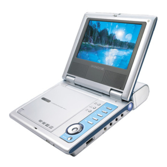
1 General Descriptions 1.1 Model Features Video: DVD Playback, MPEG4(option) ,DivX(DivX Model),Kodak Picture CD compatible & JPEG readable Audio: CD, CD-R, CD-RW, MP3, WMA Playback Firmware Upgradable Dolby Digital Output 7" active-matrix TFT screen, 16:9 wide aspect ratio Composite Video Output Ultra dimension &... -
Page 5: Information
1.2 Information Disk Format DVD, VCD, CD, MP3, CD-R, CD-RW, MPEG4 (OPTION),JPEG, Kodak Picture CD, DivX(DivX Model),WMA Video System NTSC / PAL/Auto Video Decompression MPEG-2 (ISO/IEC-13818), MPEG-1 800~1200mVpp/75 ohm Video Output Audio Characteristic 2-Channel Analog 1.0~2.0Vrms/10K ohm Analog Output Frequency Response DVD: 48kHz Sampling: 20Hz-20kHz CD: 20Hz-20kHz S/N Ratio... -
Page 6: Electrical Characteristics
2 Electrical Characteristics 2.1 Optical Characteristics Parameter Specifications Unit Screen Size 7.0 (16:9 diagonal) inch Display Format 1400 (H) 234 (V) Active Area 154.08 (H) 86.08 (V) Dot Pitch 0.107 (H) 0.370 (V) Pixel Configuration Stripe Outline Dimension 166.0 (W) Ø 100.0 (H) Ø 7.2 (D)(typ.) Surface Treatment Anti-Glare and Hard Coating 180 ±... -
Page 7: System Block Diagram
2.3 System Block Diagram 2.3.1. The System Block Diagram & the Block's Function Description INVERTER DISPLAY 7” TFT LCD PW070XU3 DC To DC MP1580 TFT LCD Driver IR3Y29B +HX8806 Loader DM-520A 2. Servo +MPEG MT1389D/MT1389C - 4 -... -
Page 8: Schematic Circuit Diagram
2.4 Schematic Circuit Diagram ( 1 ) P O W E R _ M P S - 5 -... - Page 9 (2) POWER FOR TFT - 6 -...
- Page 10 (3) SERVO&MPEG RFVDD3 IOA18 AVDD3 R175 DVSS IREF 0.1uF IOA19 RFGC 0.1uF DVDD3 PWR# IOWR# RFGND 0.033uF DVDD3 CRTPLP R170 100k V1P4 HIGHA7 HRFZC 0.1uF 1000pF HIGHA6 RFRPAC 20pF HIGHA5 RFRPDC RFVDD3 HIGHA4 RFVDD3 0.1uF HIGHA3 ADCVSS RFVDD3 HIGHA2 ADCVDD3 0.047uF HIGHA1 LPFOP...
- Page 11 (4) SDRAM&FLASH&EEPROM - 8 -...
- Page 12 (5) VIDEO OUTPUT - 9 -...
- Page 13 (6) AUDIO OUTPUT 680pF PHONE_ON 680pF 680pF 680pF - 10 -...
-
Page 14: Power
3 Power 3.1 Power Supply Input voltage: Normal voltage: 100 to 240 Vac. Variation range: 90 to 264 Vac. Input frequency: Normal frequency: 50 to 60 Hz. Variation range: 47 to 63 Hz. Input current: 0.6 arms max. at any input voltage and max. DC output rated load. Inrush current: 70 amps max. - Page 15 A thermal fuse must be added on the surface of cell body to protect the battery pack. A polyswitch must be add to protect the battery pack. Charge & Play Time of Battery Pack Charge Time DVD Title Styling (hr) Play Time (hr) Ni-MH 2400mAh (6S1P) For DPC-7900 Series - 12 -...
-
Page 16: Dimension & Physical Characteristics
4 Dimension & Physical Characteristics 4.1 Outline Dimension 205mm(L) x 163.5mm(W) x 38mm(H) 4.2 Physical Characteristics 1.LCD SCREEN 2.TFT ON/OFF KNOB 3.DISC MENU 4.PREV 5.TV MODE 6.NEXT 7.SUB TITLE 8.PLAY 9.PAUSE 10.STOP 11.ENTER 12.DIRECTION BUTTONS/FR,FF 13.SETUP 14.OPEN/PUSH 15.SPEAKERS - 13 -... -
Page 17: Exploded View
4.3 Exploded View 4.3.1 DVD Door & Mainbody_top module - 14 -... - Page 18 4.3 Exploded View 4.3.2 Keyboard & Mainbody_top module - 15 -...
- Page 19 4.3 Exploded View 4.3.3 Mecha & Mainbody_bottom module - 16 -...
- Page 20 4.3 Exploded View 4.3.4 Mainbody module - 17-...
- Page 21 4.3 Exploded View 4.3.5 Display module & Mainbody module - 18 -...
-
Page 22: Regulatory Standards
Standards Regulatory 5.1 Safety 5.2 EMI 5.3 Ergonomics Dolby - 19 -... -
Page 23: Service Tools And Equipment
6 Service Tools and Equipment 6.1Service Tools and Equipment Table Application Name General DVD Testing Disc General Tools screwdriver etc. Confirm CD Testing Disc VCD Testing Disc Adjust Oscillograph Probes AV Cables TV Monitor Searing-iron Grounding for electrostatic breakdown Antistatic wrist strap Conductive material steel sheet 6.2 Storing and Handling Test Discs It is important for a DVD testing disc keeping its surface precise. -
Page 24: Notes
3. Do not place the disc on a glass surface. It may damage the disc. If this happened, please use a new testing disc adjust DVD player precision. 6.3 Notes PLEASE READ ALL NOTES GIVEN IN THIS MANUAL. ■ Locate ●... - Page 25 or death. ● This unit should be situated away from heat source, such as amplifiers, radiators, stoves or any other units producing heat. ■ Condensation Lens could be moistening in these cases. ● Turn on heater shortly, ● In a very wet room, ●...
-
Page 26: Spare Parts
7 Spare Parts 7.1 Key Parts List Location Part NO Part Name Description Maker Remark GKB2.855.8105MX MEPG Board Hiteker W/O DivX Main Board GKB2.855.8138MX MEPG Board(With DivX) Hiteker With DivX MT1389QE_D MTK1389D W/O DivX MPEG IC ICMT1389DE-C MTK1389C With DivX AT49LV4096AT-70TC 4M Memory ATMEL... -
Page 27: Trouble Shooting
8 Trouble Shooting 8.1 Error Code Table CODE Descriptions of Error Note Power Test No power no action Power Led indicator is not on or insufficient brightness Loading time too long Remote control bad sensing or not functional System stays in the Run In condition after power on, can’t be tested System down at power on System down during playing Power on unstable... -
Page 28: Debug & Trouble Shooting
MP3 abnormal sound Audio no waveform (sound) or waveform (sound) abnormal Earphone Test Earphone no sound or the sound has pause, abnormal sound, noise, echo Earphone (right) no sound or the sound has pause, abnormal sound, noise Earphone (left) no sound or the sound has pause, abnormal sound, noise Function Key Test Video can’t be still or stop Can’t execute fast forward or rewind... - Page 29 Please replace with a good one. Disassemble F/W, replace with a good one or re-plug it to see if the LED lights up when Power ON. If the above actions are not working, replace the Main Board. T03 Loading time too long Main Board A.
- Page 30 C. Remove the top cover, check all flat cables in the system to see if they are correctly plugged to the fixed positions, or re-plug them. D. Check the capacitors C19 and the diode D6 to see if the reset circuit works normally. E.
- Page 31 replace the main board. T13 Disc drive scratches disc Main Board A. Check the resistors or capacitors adjacent to IC(U17) to see if there is any hollow soldering, cold soldering, wrong part, or misplaced soldering. If the above actions are not working, replace the loader. If it is still not working, replace the main board.
- Page 32 correctly plugged to the fixed positions, or re-plug them. Use oscilloscope to measure if Y1 generates 27MHz. If it does not generate said frequency, and the problems such as cold or hollow soldering have been ruled out, it maybe Y1 work abnormally . Replace Y1 with a 27MHz fundamental frequency oscillater.
- Page 33 D. If the above actions do not work, then check U17 Pin179 and Pin181 to see if there is Y and C signals. If the above actions are not working, replace the Main Board. T24 VCD abnormal picture Main Board A.
- Page 34 B. Remove and dis-assemble U7 with a 16Mbit SDRAM. If the above actions are not working, replace the Main Board. T31 Audio /left channel (AOL) no sound or abnormal sound Main Board A. Remove the cover. Check U15 on the Main board to see if there is any cold soldering, hollow soldering, or damage.
- Page 35 Check U19,U15 and J4,CON3 to see if there is any cold or hollow soldering and rule out the problem. If the above action does not work after the inspection, replace the main board. T42 Earphone Audio right no waveform (sound) or waveform (sound ) abnormal Main Board A.
- Page 36 Main Board A. Check U17 to see if there is any cold or hollow soldering and reverse soldering of IC or parts missing. If the above actions do not work after the inspection, it means the main board or F/W is bad. If the disk is abnormal, ask for a new version software .
- Page 37 A. Measure the voltages of VGH,VGE,VCC,VDD,VIN and VSS to see if they are correct. Check VC1 to see if there is any cold or hollow soldering and reverse soldering of IC or parts missing. Check the devices surrounding U1 and U201 to see if there is any cold or hollow soldering and reverse soldering of IC or parts missing.
- Page 38 of IC or parts missing. Check Pin 1 to Pin 16 on U202 for any cold or hollow soldering and reverse soldering of IC or parts missing. F. If the above actions are not working, replace the Driver Board. T75 TFT ripple Main Board A.
Need help?
Do you have a question about the DPC-7900 Series and is the answer not in the manual?
Questions and answers