Table of Contents
Advertisement
Advertisement
Table of Contents

Subscribe to Our Youtube Channel
Related Manuals for ECS H61H-G11


Summary of Contents for ECS H61H-G11
- Page 1 Инструкция для ECS G11 Перейти в карточку товара 8 800 775 98 98...
- Page 2 Preface Copyright This publication, including all photographs, illustrations and software, is protected under international copyright laws, with all rights reserved. Neither this manual, nor any of the material contained herein, may be reproduced without written consent of the author. Version 1.0A Disclaimer The information in this document is subject to change without notice.
-
Page 3: Declaration Of Conformity
Declaration of Conformity This device complies with part 15 of the FCC rules. Operation is subject to the following conditions: • This device may not cause harmful interference. • This device must accept any interference received, including interfer- ence that may cause undesired operation. Canadian Department of Communications This class B digital apparatus meets all requirements of the Canadian Interference- causing Equipment Regulations. -
Page 4: Table Of Contents
T T T T T ABLE OF CONTENTS ABLE OF CONTENTS ABLE OF CONTENTS ABLE OF CONTENTS ABLE OF CONTENTS Preface Chapter 1 Introducing the Motherboard Introduction...................1 Feature....................2 Specifications................4 Motherboard Components............5 7 7 7 7 7 Chapter 2 Installing the Motherboard Safety Precautions................7 Choosing a Computer Case.............7 Installing the Motherboard in a Case..........7... - Page 5 Boot Menu................37 Security Menu................38 Exit Menu................39 Updating the BIOS..............40 41 41 41 41 41 Chapter 4 Using the Motherboard Software About the Software DVD-ROM/CD-ROM........41 Auto-installing under Windows XP/Vista/7........41 ..Running Setup..............42 Manual Installation................44 Utility Software Reference..............44 Chapter 5 Trouble Shooting Start up problems during assembly..........45 Start up problems after prolong use..........46 Maintenance and care tips..............46...
-
Page 6: Introducing The Motherboard
Chapter 1 Introducing the Motherboard Introduction Thank you for choosing the H61H-G11 motherboard. This motherboard is a high performance, enhanced function motherboard designed to support the LGA1155 socket for Intel ® Generation Core processors for high-end business or per- sonal desktop markets. -
Page 7: Feature
Feature Processor The motherboard uses a LGA1155 type of socket that carries the following features: ® • Accommodates Intel Generation Core processors • Supports “Hyper-Threading” technology CPU “Hyper-Threading” technology enables the operating system into thinking it’s hooked up to two processors, allowing two threads to be run in parallel, both on separate “logical”... -
Page 8: Bios Firmware
Giga LAN (Optional) The onboard LAN provides the following features: • Supports PCI Express • Integrated 10/100/1000 transceiver • Wake-on-LAN and remote wake-up support Expansion Options The motherboard comes with the following expansion options: • One Mini PCI Express slot (supports half-card) •... -
Page 9: Specifications
Specifications ® • LGA1155 socket for Intel Generation Core proces- sors • Supports “Hyper-Threading” technology CPU • DMI 2.0GT/s Chipset ® • Intel H61 Chipset Memory • Dual-channel DDR3 memory architecture • 2 x 240-pin DDR3 SO-DIMM sockets support up to 8 GB •... -
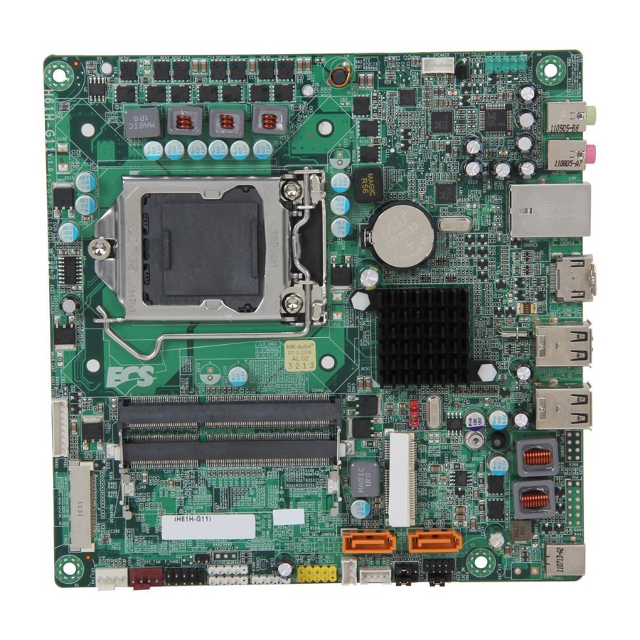
Page 10: Motherboard Components
Motherboard Components Introducing the Motherboard... - Page 11 Table of Motherboard Components LABEL COMPONENTS ® LGA1155 socket for Intel Generation 1. CPU Socket Core Processors 2. SPEAKER Speaker header 3. F_AUDIO Front panel audio header 4. CLR_CMOS Clear CMOS jumper 5. MINI-PCIE1X Mini PCI Express x1 slot (supports half-card) 6.
-
Page 12: Installing The Motherboard
Chapter 2 Installing the Motherboard Safety Precautions • Follow these safety precautions when installing the motherboard • Wear a grounding strap attached to a grounded device to avoid dam- age from static electricity • Discharge static electricity by touching the metal case of a safely grounded object before working on the motherboard •... -
Page 13: Checking Jumper Settings
Do not over-tighten the screws as this can stress the motherboard. Checking Jumper Settings This section explains how to set jumpers for correct configuration of the motherboard. Setting Jumpers Use the motherboard jumpers to set system configuration options. Jumpers with more than one pin are numbered. -
Page 14: Checking Jumper Settings
Checking Jumper Settings The following illustration shows the location of the motherboard jumpers. Pin 1 is labeled. Jumper Settings Jumper Type Description Setting (default) 1-2: NORMAL 2-3: CLEAR CLR_CMOS 3-pin Clear CMOS Before clearing the CMOS, make sure to CLR_CMOS turn off the system. -
Page 15: Installing Hardware
To avoid the system instability after clearing CMOS, we recommend users to enter the main BIOS setting page to “Load Default Settings” and then “Save and Exit Setup”. Installing Hardware Installing the Processor Caution: When installing a CPU heatsink and cooling fan make sure that you DO NOT scratch the motherboard or any of the surface-mount resis- tors with the clip of the cooling fan. -
Page 16: Cpu Installation Procedure
CPU Installation Procedure The following illustration shows CPU installation components. A. Disengaging of the Load Lever · Press the hook of lever down and pull it to the right side to release it from retention tab. B. Opening of the Load Plate ·... -
Page 17: Installing Memory Modules
1. To achieve better airflow rates and heat dissipation, we suggest that you use a high quality fan with 3800 rpm at least. CPU fan and heatsink installation procedures may vary with the type of CPU fan/ heatsink supplied. The form and size of fan/heatsink may also vary. 2. - Page 18 * For reference only Installing the Motherboard...
-
Page 19: Expansion Slots
Expansion Slots Installing Add-on Cards The slots on this motherboard are designed to hold expansion cards and connect them to the system bus. Expansion slots are a means of adding or enhancing the motherboard’s features and capabilities. With these efficient facilities, you can in- crease the motherboard’s capabilities by adding hardware that performs tasks that are not part of the basic system. -
Page 20: Connecting Optional Devices
Connecting Optional Devices Refer to the following for information on connecting the motherboard’s optional devices: F_AUDIO: Front Panel Audio header This header allows the user to install auxiliary front-oriented microphone and line- out ports for easier access. Signal Name Signal Name PORT 1L AUD_GND PORT 1R... - Page 21 F_USB1: Front Panel USB header The motherboard has one USB 2.0 header supporting two USB 2.0 ports. Addition- ally, some computer cases have USB 2.0 ports at the front of the case. If you have this kind of case, use auxiliary USB 2.0 connector to connect the front-mounted ports to the motherboard.
- Page 22 ODD_PW: ODD power connector This connector is used to provide power for the 0DD. Signal Name TS: Touch board header Signal Name USB_N USB_P CAMERA: CCD header Signal Name USB_N USB_P MCR: Card reader header Signal Name USB_N USB_P LCD_OFF: Panel switch This connector is used to provide power for the 0DD.
-
Page 23: Installing A Sata Hard Drive
Installing a SATA Hard Drive This section describes how to install a SATA Hard Drive. About SATA Connectors Your motherboard features two SATA connectors supporting a total of two drives. SATA refers to Serial ATA (Advanced Technology Attachment) is the standard inter- face for the IDE hard drives which are currently used in most PCs. -
Page 24: Connecting I/O Devices
Connecting I/O Devices The backplane of the motherboard has the following I/O ports: DC_IN Port Connect the DC_IN port to the power adapter. USB 2.0 Ports Use the USB 2.0 ports to connect USB 2.0 devices. HDMI Port Connect the HDMI port to the HDMI devices. Connect an RJ-45 jack to the LAN port to connect your LAN Port computer to the Network. -
Page 25: Connecting Case Components
Connecting Case Components After you have installed the motherboard into a case, you can begin connecting the motherboard components. Refer to the following: Connect the CPU cooling fan cable to CPU_FAN. Connect the case switches and indicator LEDs to the F_PANEL. Connect the system cooling fan connector to SYS_FAN. - Page 26 CPU_FAN: CPU cooling FAN Power Connector Signal Name Function System Ground Power +12V +12V Sense Sensor Users please note that the fan connector supports the CPU cooling fan of 1.1A ~ 2.2A (26.4W max) at +12V. SYS_FAN: System Cooling FAN Power Connectors Signal Name Function System Ground...
-
Page 27: Front Panel Header
Front Panel Header The front panel header (F_PANEL) provides a standard set of switch and LED headers commonly found on ATX or Micro ATX cases. Refer to the table below for informa- tion: Signal Function Signal Function HD_LED_P Hard disk LED(+) 2 FP PWR/SLP *MSG LED(+) HD_LED_N Hard disk LED(- ) FP PWR/SLP *MSG LED(-) -
Page 28: Using Bios
Chapter 3 Using BIOS About the Setup Utility The computer uses the latest “American Megatrends Inc.” BIOS with support for Windows Plug and Play. The CMOS chip on the motherboard contains the ROM setup instructions for configuring the motherboard BIOS. The BIOS (Basic Input and Output System) Setup Utility displays the system’s configuration status and provides you with options to set system parameters. -
Page 29: Resetting The Default Cmos Values
Press the delete key to access BIOS Setup Utility. Aptio Setup Utility - Copyright (C) 2011 American Megatrends, Inc. Main Advanced Chipset Boot Security Exit Choose the system default BIOS Information language System Language [English] System Data [Tue 04/10/2012] :Select Screen System Time [21:32:56] :Select Item... -
Page 30: Bios Navigation Keys
In this manual, default values are enclosed in parenthesis. Submenu items are denoted by a triangle The default BIOS setting for this motherboard apply for most conditions with optimum performance. We do not suggest users change the default values in the BIOS setup and take no responsibility to any damage caused by changing the BIOS settings. -
Page 31: Advanced Menu
System Language This item is used to set system language. System Date & Time The Date and Time items show the current date and time on the computer. If you are running a Windows OS, these items are automatically updated whenever you make changes to the Windows Date and Time Properties utility. -
Page 32: Lan Configuration
LAN Configuration The item in the menu shows the LAN-related information that the BIOS automatically detects. Aptio Setup Utility - Copyright (C) 2011 American Megatrends, Inc. Main Advanced Chipset Boot Security Exit Enabled/Disabled Onboard LAN 1 LAN Configuration Controller Onboard LAN Controller [Enabled] :Select Screen :Select Item... -
Page 33: Pc Health Status
PC Health Status On motherboards support hardware monitoring, this item lets you monitor the parameters for critical voltages, temperatures and fan speeds. Aptio Setup Utility - Copyright (C) 2011 American Megatrends, Inc. Main Advanced Chipset Boot Security Exit Smart Fan Function PC Health Status Smart Fan Function CPU Fan Speed... - Page 34 Smart Fan start PWM value (180) This item is used to set the start PWM value of the smart fan. Smart Fan start PWM TEMP(-) (30) This item is used to set the start temperature of the smart fan. DeltaT (+3) This item specifies the range that controls CPU temperature and keeps it from going so high or so low when smart fan works.
-
Page 35: Power Management Setup
Power Management Setup This page sets up some parameters for system power management operation. Aptio Setup Utility - Copyright (C) 2011 American Megatrends, Inc. Main Advanced Chipset Boot Security Exit Power Management Setup About Resume by PME Resume By PME [Disabled] Resume By USB 1.x/2.0 (S3) [Disabled]... -
Page 36: Acpi Setting
ACPI Setting The item in the menu shows the highest ACPI sleep state when the system enters suspend. Aptio Setup Utility - Copyright (C) 2011 American Megatrends, Inc. Main Advanced Chipset Boot Security Exit ACPI Settings Select the highest ACPI sleep state the system will enter ACPI Sleep State [S3 (Suspend to RAM)]... - Page 37 Intel(R) Core(TM) i5-2500S CPU @ 2.70GHz This is display-only field and diaplays the information of the CPU installed in your computer. EMT64 (Supported) This item shows the computer supports EMT64. Processor Speed (2700MHz) This item shows the current processor speed. Processor Stepping (206a7) This item shows the processor stepping version.
-
Page 38: Sata Configuration
SATA Configuration Use this item to show the mode of serial SATA configuration options. Aptio Setup Utility - Copyright (C) 2011 American Megatrends, Inc. Main Advanced Chipset Boot Security Exit Determines how SATA SATA Configuration controller(s) operate. SATA Mode [IDE Mode] :Select Screen SATA Port1 :Select Item... -
Page 39: Chipset Menu
Chipset Menu The chipset menu items allow you to change the settings for the North chipset, South chipset and other system. Aptio Setup Utility - Copyright (C) 2011 American Megatrends, Inc. Main Advanced Chipset Boot Security Exit System Agent (SA) Parameters System Agent Configuration PCH Configuration ME Configuration... - Page 40 PCH Configuration Scroll to this item and press <Enter> to view the following screen: Aptio Setup Utility - Copyright (C) 2011 American Megatrends, Inc. Main Advanced Chipset Boot Security Exit PCH Configuration Select AC power state when power is re-applied after a Restore AC Power Loss [Power Off] power failure.
- Page 41 ME Configuration Scroll to this item and press <Enter> to view the following screen: Aptio Setup Utility - Copyright (C) 2011 American Megatrends, Inc. Main Advanced Chipset Boot Security Exit Managemnet Engine Tehnology Configuration ME FW Version 8.0.2.1410 :Select Screen :Select Item Enter : Select +/- : Change Opt.
-
Page 42: Boot Menu
Boot Menu This page enables you to set the keyboard NumLock state. Aptio Setup Utility - Copyright (C) 2011 American Megatrends, Inc. Main Advanced Chipset Boot Security Exit Select the keyboard NumLock Boot Configuration state Bootup NumLock State [On] Set Boot Prioritiy 1st Boot [Hard Disk] 2nd Boot... -
Page 43: Security Menu
USB HardDisk Drive Priorities (Press Enter) This item enables you to specify the sequence of loading the operating system from the installing USB harddisk drives. USB Flash Drive Priorities (Press Enter) This item enables you to specify the sequence of loading the operating system from the installing USB flash drives. -
Page 44: Exit Menu
Exit Menu This page enables you to set setup administrator and password. Aptio Setup Utility - Copyright (C) 2011 American Megatrends, Inc. Main Advanced Chipset Boot Security Exit Exit system setup after saving Save Changes and Exit the changes. Discard Changes and Exit Save Changes and Reset Discard Changes and Reset :Select Screen... -
Page 45: Updating The Bios
Updating the BIOS You can download and install updated BIOS for this motherboard from the manufacturer’s Web site. New BIOS provides support for new peripherals, improve- ments in performance, or fixes for known bugs. Install new BIOS as follows: If your motherboard has a BIOS protection jumper, change the setting to allow BIOS flashing. -
Page 46: Using The Motherboard Software
Chapter 4 Using the Motherboard Software About the Software DVD-ROM/CD-ROM The support software DVD-ROM/CD-ROM that is included in the motherboard package contains all the drivers and utility programs needed to properly run the bundled products. Below you can find a brief description of each software program, and the location for your motherboard version. -
Page 47: Running Setup
Drivers Click the Setup button to run the software installation program. Setup Select from the menu which software you want to install. Click the Utilities button to display the application software and Utilities other software utilities that are available on the disk. Select the sofware you want to install then follow installation procedure. - Page 48 Click Next. The following screen appears: Check the box next to the items you want to install. The default options are recom- mended. Click Next run the Installation Wizard. An item installation screen appears: Follow the instructions on the screen to install the items. Drivers and software are automatically installed in sequence.
-
Page 49: Manual Installation
Windows Vista/7 will appear below UAC (User Account Control) message after the system restart. You must select “Allow” to install the next driver. Continue this process to complete the drivers installation. Manual Installation Insert the disk in the DVD-ROM/CD-ROM drive and locate the PATH.DOC file in the root directory. -
Page 50: Trouble Shooting
Chapter 5 Trouble Shooting Start up problems during assembly After assembling the PC for the first time you may experience some start up problems. Before calling for technical support or returning for warranty, this chapter may help to address some of the common questions using some basic troubleshooting tips. -
Page 51: Start Up Problems After Prolong Use
2. From the BIOS setting, try to disable the Smartfan function to let the fan run at default speed. Doing a Load Optimised Default will also disable the Smartfan. Start up problems after prolong use After a prolong period of use your PC may experience start up problems again. This may be caused by breakdown of devices connected to the motherboard such as HDD, CPU fan, etc. -
Page 52: Basic Troubleshooting Flowchart
Basic Troubleshooting Flowchart... - Page 53 Memo Trouble Shooting...
- Page 54 ECS G11 Описание Характеристики...
Need help?
Do you have a question about the H61H-G11 and is the answer not in the manual?
Questions and answers