
Subscribe to Our Youtube Channel
Related Manuals for Texas Instruments TPA731 MSOP


Summary of Contents for Texas Instruments TPA731 MSOP
- Page 1 TPA731 MSOP Audio Power Amplifier Evaluation Module User’s Guide November 2000 Mixed-Signal Products SLOU088...
- Page 2 IMPORTANT NOTICE Texas Instruments and its subsidiaries (TI) reserve the right to make changes to their products or to discontinue any product or service without notice, and advise customers to obtain the latest version of relevant information to verify, before placing orders, that information being relied on is current and complete. All products are sold subject to the terms and conditions of sale supplied at the time of order acknowledgment, including those pertaining to warranty, patent infringement, and limitation of liability.
-
Page 3: Read This First
Information About Cautions and Warnings Preface Read This First Information About Cautions and Warnings This book may contain cautions and warnings. This is an example of a caution statement. A caution statement describes a situation that could potentially damage your software or equipment. This is an example of a warning statement. - Page 4 FCC Warning FCC Warning This equipment is intended for use in a laboratory test environment only. It generates, uses, and can radiate radio frequency energy and has not been tested for compliance with the limits of computing devices pursuant to subpart J of part 15 of FCC rules, which are designed to provide reasonable protection against radio frequency interference.
-
Page 5: Table Of Contents
..............2–2. Platform Jumper and Switch Settings for the TPA731 MSOP EVM . -
Page 7: Introduction
..........Description 1–3 ......TPA731 MSOP EVM Specifications 1–3 Introduction... -
Page 8: Feature Highlights
Feature Highlights 1.1 Feature Highlights The TI TPA731 MSOP audio amplifier evaluation module and the TI plug-n-play audio amplifier evaluation platform include the following features: TPA731 low-voltage audio power amplifier evaluation module Single channel, bridge-tied load (BTL) 2.5-V and 5.5-V operation... -
Page 9: Description
The platform, with room for a pair of TPA731 MSOP evaluation modules, is a convenient vehicle for demonstrating TI’s audio power amplifier and related evaluation modules. - Page 10 Introduction...
-
Page 11: Operation
Chapter 2 Operation Follow the steps in this chapter to quickly prepare the TPA731 MSOP audio amplifier EVM for use. Using the TPA731 MSOP EVM with the TI plug-n-play audio amplifier evaluation platform is a quick and easy way to connect power, signal and control inputs, and signal outputs to the EVM, using standard connectors. -
Page 12: Precautions
Precautions 2.1 Precautions Power Supply Input Polarity and Maximum Voltage Always ensure that the polarity and voltage of the external power connected to V power input connector J1, J2, and/or V power input connector J6 are correct. Overvoltage or reverse-polarity power applied to these terminals can open onboard soldered-in fuses and cause other damage to the platform, installed evaluation modules, and/or the power source. -
Page 13: Quick Start List For Platform
1) Ensure that all external power sources are set to off and that the platform power switch S1 is set to off. 2) Install a TPA731 MSOP module in platform sockets U3 and U4 for stereo operation (or a module in either U3 or U4 for single channel operation), taking care to align the module pins correctly. -
Page 14: Quick Start List For Stand-Alone
Quick Start List for Stand-Alone 2.3 Quick Start List for Stand-Alone Follow these steps to use the TPA731 MSOP EVM stand-alone or when connecting it into existing circuits or equipment. Connections to the TPA731 MSOP module header pins can be made via individual sockets, wire-wrapping, or soldering to the pins, either on the top or the bottom of the module circuit board. -
Page 15: Reference
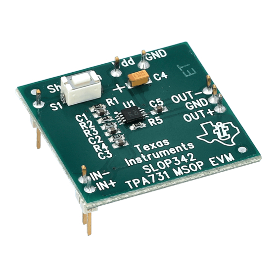
Reference 2.4 Reference 2.4.1 TPA731 MSOP EVM Connected for BTL Output Figure 2–3. TPA731 MSOP EVM Connected for Stereo BTL Output 5 VDC Vdd GND Shutdown U1 † OUT– Right OUT+ TEXAS INSTRUMENTS Audio Input IN– (Right) SLOP342 TPA731 MSOP EVM... -
Page 16: Tpa731 Msop Evm Schematic Diagram
39 k In – OUT+ 20 k Audio Input– 5 pF 39 k 20 k 2.4.3 TPA731 MSOP Audio Power Amplifier Evaluation Module Parts List Table 2–3. TPA731 MSOP EVM Parts List Manufacturer/ Vendor Reference Description Size Qty. Part Number Number Capacitor, 10 F, 6.3 V... -
Page 17: Tpa731 Evm Pcb
TPA731 MSOP EVM PCB Layers 2.4.4 TPA731 MSOP EVM PCB Layers The following illustrations depict the TPA731 EVM PCB layers and silkscreen. These drawings are not to scale. Gerber plots can be obtained from any TI sales office. Figure 2–5. TPA731 EVM PCB Figure 2–6. -
Page 18: Tpa731 Evm Top Layer
TPA731 MSOP EVM PCB Layers Figure 2–7. TPA731 EVM Top Layer Figure 2–8. TPA731 EVM Bottom Layer Operation...
Need help?
Do you have a question about the TPA731 MSOP and is the answer not in the manual?
Questions and answers