
Related Manuals for Holder C-Trac A4 VG 40 EP


Summary of Contents for Holder C-Trac A4 VG 40 EP
-
Page 1: Operating Instructions
Operating Instructions C-Trac C 9700 C 9700 H C 9800 H C 9.72 C 9.72 H C 9.83 H C 9.78 H C 9.88 H Order No.: 145 052 Date of Issue: 17.11.2006... -
Page 3: Foreword
C 9700 ... C 9.88 H Foreword We congratulate you for having chosen a product from HOLDER. We would like you to be able to work safely with your tractor and without malfunctions, and therefore we recommend you follow the instructions in this operating manual. - Page 4 Operating Hours ... eg 500 service hours Date of Issue and Manual Version November 2006 We wish you safe driving and troublefree working with your HOLDER C-Trac. Gebrüder Holder GmbH Max-Holder-Straße 1 72555 Metzingen Phone (Germany) 07123 966 - 0 Fax 07123 966 - 228 E-mail: info@holder-gmbh.com...
-
Page 5: Table Of Contents
C 9700 ... C 9.88 H Table of Contents Chapter Foreword ... 1 Instructions for the Tractor ... 5 Instructions for Operation ... 7 Technical Data ... 15 Description ... 28 Taking into Service ... 49 Operation ... 65 Operating the Implements ... 87 Other Activities ... -
Page 7: Instructions For The Tractor
Unintended Applications Any use not intended as described as above is not authorized. The Supplier HOLDER will not be responsible for any hazard resulting from unintended applications. The Supplier will also not be responsible for any resulting damages, they shall be solely borne by the user. - Page 8 Operating Instructions Instructions for the Tractor Residual Hazards and Risks Despite all care being taken and in conformance with standards and regulations, it is not possible to exclude all risks in the handling of the tractor. The tractor and all other system components conform to currently applicable safety regulations.
-
Page 9: Instructions For Operation
Operating Instructions C 9700 ... C 9.88 H Instructions for Operation Driver's license For the operation of this vehicle you need a driver's license dependent of the maximum speed and the permissible total weight of the vehicle or the combination. See the tables below. - Page 10 Operating Instructions C 9700 ... C 9.88 H Instructions for Operation Single-axle Trailers or Two-axle Trailers with an Axle Base of up to max. 1 m 145 052...
- Page 11 Operating Instructions C 9700 ... C 9.88 H Instructions for Operation Multiple-axle Trailers and Two-axle Trailers with an Axle Base over 1 m 145 052...
- Page 12 Operating Instructions C 9700 ... C 9.88 H Instructions for Operation Two Trailers behind Tractors for Farming and Forestry 145 052...
- Page 13 C 9700 ... C 9.88 H Safety General Notes on Safety • Observe the VSG 3.1 (German regulations for safety and health protection). • Do not allow children under 16 to use the tractor. • When using the public highway, respect the highway code.
- Page 14 Operating Instructions Instructions for Operation • The installed equipment must conform to the applica- ble EMC directive 89/336/EU and carry the CE symbol. • If you must install a mobile communications system (or have it installed) (eg radio, mobile telephone), the following requirements must be met: Only approved equipment (eg BTZ approval in Germa- ny) may be installed.
- Page 15 C 9700 ... C 9.88 H let them come in contact with hot engine parts as fire can result. Hydraulic Oil, Brake Fluid During tractor operation, these fluids are under pressure and a health hazard. Do not spill these fluids! Remove any spilled fluid at once with an oil binding agent and discard as specified.
- Page 16 Operating Instructions Instructions for Operation particles in the exhaust gases can cause cancer. For this reason the engine may not be operated in enclosed spaces. Heat The exhaust gases are very hot and can ignite inflammable material. The exhaust gas pipe should therefore be kept away from ignitable material.
-
Page 17: Technical Data
C 9700 ... C 9.88 H Technical Data Model Variants 145 052 Operating Instructions... - Page 18 Operating Instructions Technical data Tractor Dimensions Sketch 1040-1160 Data in brackets are American dimensions 1827 (40,9-45,6") (72") 1030 1110 3900-4020 (153,5-158,3") 3980-4100 (156,5-161,4") C 9700 ... C 9.88 H (38,2") 1090 (42,9") (Cab for 1 person) (40,5") 1250 (49,3") (43,1") (Cab for 2 persons) Bild_194 145 052...
- Page 19 Operating Instructions C 9700 ... C 9.88 H Technical data Table of Dimensions 145 052...
- Page 20 Operating Instructions C 9700 ... C 9.88 H Technical data Track Widths 145 052...
- Page 21 Operating Instructions C 9700 ... C 9.88 H Technical data Weights 145 052...
- Page 22 Operating Instructions Technical data Tires The pressure can deviate, depending on the make and use of the tyres – observe the instructions of the tyre manufacturers. Type of Tire Profile 10.5-18 MPT S Cleat profile 10.5-18 MPT Cleat profile 31x15.50-15* Profile 33x15.50-15 Profile...
- Page 23 Operating Instructions C 9700 ... C 9.88 H Technical data Engine Specifications 145 052...
- Page 24 Operating Instructions C 9700 ... C 9.88 H Technical data Theoretical Driving Speeds 145 052...
- Page 25 Operating Instructions C 9700 ... C 9.88 H Technical data Technical Data/Filling Quantities 145 052...
- Page 26 Operating Instructions C 9700 ... C 9.88 H Technical data 145 052...
- Page 27 Operating Instructions C 9700 ... C 9.88 H Technical data 145 052...
- Page 28 Operating Instructions Technical data Assembly Hydraulics for implements (with steering) Pump - Make - Flow rate - Operating pressure Hydraulic oil tank Electrical System - Operating voltage - Battery - A/C alternator - Starter Whole Vehicle - Ambient temperature range Suppl.
- Page 29 Operating Instructions C 9700 ... C 9.88 H Technical data Noise Level The tractor emits the following noise level (measured at the driver's ear) according to EU Standard 77/311/EEC; measurement according to Appendix II. Table of Noise Levels and Absorption Rating Exhaust Gas Identification The absorption rating is stated on the identification plate.
-
Page 30: Description
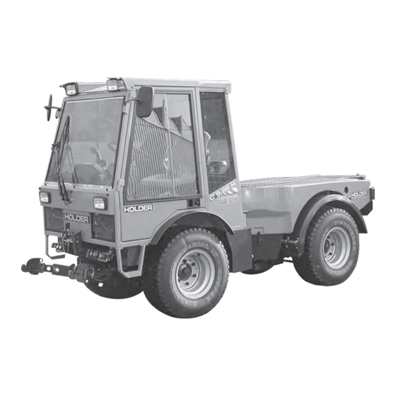
Operating Instructions Description Views of Tractor Front Left View 1 Turn signal, position light 2 Headlight, top 3 Driver's cab 4 Dump body (dump) 5 Rear of vehicle 6 Engine oil dipstick 7 Battery isolating switch 8 Rear axle 9 Hydraulic oil tank and filler neck (drive hydraulics) 10 Front axle... - Page 31 C 9700 ... C 9.88 H Tractor Rear Right View 1 Dump Body 2 Fuel filler neck 3 Oil filler neck for implement hydrau- lics 4 Intake screen for fresh air blower 5 Support for rotating beacon 6 Flood light* 7 Driver's cab 8 Front part of tractor 9 Front axle...
- Page 32 Operating Instructions Description Driver's Station Operating controls 1 Light switch 2 Differential lock switch 3 Pressure gauge for hydraulic carrier* 4 Steering wheel 5 Brake fluid reservoir 6 Control lever for dump support* 7 Implement* control lever 8 Multi-function display 9 Multi-function lever* (front lift and direction of travel) 10 Digital instrument switch (ground speed in km/h or PTO rpm)
- Page 33 C 9700 ... C 9.88 H 145 052 Operating Instructions Description 11 12...
- Page 34 Operating Instructions Description Implement* and Engine Controls (Details) 1 Control lever for dump/rear lift* 2 Control lever functions plate 3 Multi-function lever functions plate 4 Multi-function lever* (front lift and travel direction) 5 Hand throttle - Outer ring for fine adjustment: Turn clockwise to decrease rpm Turn counter-clockwise to increase rpm - Inner knob for coarse adjustment:...
- Page 35 C 9700 ... C 9.88 H Multi-function Lever NOTE Various types of multi-function levers can be installed. Multi-function Lever (Variant 1) 1 Multi-function lever without forward reverse selector lever (Forward-reverse selector installed on instru- ment board) 2 Forward/reverse selector lever 3 Note plate Driving direction 145 052...
- Page 36 Operating Instructions Description Multi-function Lever* (Variant 2) NOTE The coloured buttons control the function of the implements attached to the related hydraulic cou- plings 1 Multi-function lever 2 Blue hydraulic couplings on 3 Blue hydraulic couplings off - float position 4 LED indicator, red or green 5 Functions off 6 LED indicator, red...
- Page 37 C 9700 ... C 9.88 H Multi-function Lever* (Variant 3) 1 Forward direction arrow (illuminated if selected) 2 Reverse direction arrow (illuminated if selected) 3 Forward/reverse selector switch (left for forward - right for reverse) 4 Multi-function lever Multi-function Lever* (Variant 4) 1 Forward direction arrow (illuminated if selected) 2 Reverse direction arrow (illuminated if selected) 3 Forward/reverse selector switch (left forward - right...
- Page 38 Operating Instructions Description Foot Pedals 1 Inch pedal (clutch pedal if gearbox is fitted) 2 Brake pedal 3 Accelerator pedal Hydraulic Carrier* Control (Power Lifter) 1 Pressure adjuster 2 ON-OFF label 3 Star knob for turning on/off * Option C 9700 ... C 9.88 H Bild_005 145 052...
- Page 39 C 9700 ... C 9.88 H Operating Controls Behind the Seat 1 PTO clutch lever, ON-OFF 2 Device selector lever: - Position for dump on 3 - Position for rear lift on 4 Emergency start (Hydrostatic Drive with Dual-Drive only) Drive Range Pre-selection Lever between Seats 1 Drive range pre-selection lever 2 Drive range label...
-
Page 40: Taking Into Service
Operating Instructions Taking into Service Front PTO Selector PTO rpm label - Top position (up) - 540 rpm - Centre position - Neutral - Lower position (down) - 1000 rpm 2 PTO selector lever Heater 1 Heater temperature control 2 Heating temperature label - lever up - warmer - lever down - cooler C 9700 ... - Page 41 C 9700 ... C 9.88 H Legend for Multi-function Display 1 Display for - Ground speed in km/h or - PTO rpm x10 2 Position light indicator 3 High beam indicator 4 Turn signal indicator 5 Turn signal indicator for trailer 1 6 Turn signal indicator for trailer 2 7 Preheating indicator...
- Page 42 Operating Instructions Description Controls for Mechanical Gearbox 1 Gearshift lever (left looking forward) with 4 synchroni- zed gears 1-2-3-4 2 Range selector lever (right looking forward) with 4 speed ranges: S - Highway driving M - Medium speed L- Slow speed LL - Very slow speed 3 Gearshift label C 9700 ...
- Page 43 C 9700 ... C 9.88 H Controls on Cabin Console at Front Left 1 Front wiper/washer switch 2 Rear wiper/washer switch 3 Sun blind 4 Air vent nozzle Controls on Cabin Console at Front Right 1 Rotating beacon switch 2 Fresh air blower switch, top 3 Headlight switch, top 4 Rear floodlight switch 5 Air vent nozzle...
- Page 44 Operating Instructions Description Controls in Cabin at Rear 1 Interior light 2 Sun visor 3 Roof hatch handle 4 Roof hatch C 9700 ... C 9.88 H 145 052...
-
Page 45: Location Of Plates And Labels
C 9700 ... C 9.88 H Location of Plates and Labels Identification Plates 1 Variable motor type plate 2 Engine type plate 3 Variable pump type plate 4 Machine type plate 5 Chassis Serial Number (on front RH support looking forward) 6 Cabin type plate 145 052 Operating Instructions... - Page 46 Operating Instructions Description Mounting Instructions for License Plate Install the front license plate (1) above the upper link support at the front cabin wall. Install the rear license plate (2) at the rear below the left tail light. C 9700 ... C 9.88 H 145 052...
- Page 47 Operating Instructions C 9700 ... C 9.88 H Description Overview of Options and Variants 145 052...
- Page 48 Operating Instructions C 9700 ... C 9.88 H Description 145 052...
- Page 49 Operating Instructions C 9700 ... C 9.88 H Description 145 052...
- Page 50 The tractor is delivered with the following accessories: 1 Operating Instructions 2 Bio-Pass for certification of filling with environment- friendly hydraulic oil 3 Key holder 4 2 ignition keys 5 4 door keys 6 Upper link 7 2 reducers for category I implements C 9700 ...
-
Page 51: Taking Into Service
C 9700 ... C 9.88 H Taking into Service Daily Checks and Activities before Taking into Service If damages or defects are found during the following checks, they must be eliminated before taking the vehicle into service. Do not operate the tractor before proper repairs are carried out. - Page 52 Operating Instructions Taking into Service Turning on the Battery Isolating Switch NOTE The battery can be switched off completely with the removable key. Insert the key (1) in the battery isolating switch and set it to the vertical position. The battery circuit is turned on. Checking Engine Oil Level NOTE Check the engine oil level only when the...
- Page 53 C 9700 ... C 9.88 H Checking the Trailer Hitch (Optional), if required Check the trailer hitch for proper condition and wor- king. Carry out the check according to the instructions in the section "Operating the Trailer Hitch". Checking Tire Inflation Pressure NOTE Your tractor can be equipped with different types of tires.
- Page 54 Operating Instructions Taking into Service Checking the Drive Hydraulics Oil Level Withdraw the oil dipstick (1). The oil level must be at the marking (2). Top up oil as specified in the maintenance manual. Checking the Implement Hydraulics Oil Level Retract all hydraulic cylinders.
- Page 55 C 9700 ... C 9.88 H Filling Fuel If necessary, read the fuel level (1) on the multi- function display. CAUTION Danger of fire when handling fuels. Turn off the engine. Do not fill any fuels in the vicinity of naked flames, ignition sparks or hot engine parts.
- Page 56 Operating Instructions Taking into Service Checking the Brake Fluid Level Check the brake fluid level at the brake fluid reservoir (2). The brake fluid level must be between the Min and Max marking at the reservoir. Top up the brake fluid as specified in the maintenance manual.
- Page 57 C 9700 ... C 9.88 H Adjusting the Driver's Seat 1 Backrest 2 Adjustment knob for lumbar padding 3 Backrest adjustment 4 Weight adjustment 5 Horizontal cushioning 6 Horizontal adjustment DANGER Do not adjust the seat while driving. Risk of accidents! Adjust the seat so that all controls can be reached and operated safely.
- Page 58 Operating Instructions Taking into Service Adjusting the Driver's Weight Sit down on the driver's seat. Pull the weight adjustment handle (4) up. NOTE An alert sounds. The seat is automatically set to the weight of the driver; The alert ceases. Release the lever.
- Page 59 C 9700 ... C 9.88 H Adjusting the Passenger Seat 1 Backrest 2 Weight adjustment 3 Backrest tilt adjustment Adjusting the Weight The weight should be adjusted when the passenger seat is unoccupied. Press the weight adjustment knob (2) from the top down until the weight on the scale is reached.
- Page 60 Operating Instructions Taking into Service Filling Washing Water NOTE The washing water reservoir for the windshield washer is located beneath the passenger seat. Tilt the seat forward. Open the filler cap (1) and add washing water into the reservoir (2). Filling capacity ...
-
Page 61: Starting The Engine
C 9700 ... C 9.88 H 145 052 Operating Instructions Starting the Engine Instructions before Starting the Engine DANGER Do not start or run the engine in enclosed spaces. Danger of poisoning through exhaust gases! Instructions before Starting CAUTION Before starting, check to ensure no one is in the vicinity of the tractor. - Page 62 Operating Instructions Taking into Service Starting the Engine Shift the gearshift lever (gearbox) to neutral. Set the forward/reverse selector lever (1) to the neutral position (centre). Depress the clutch pedal (gearbox) or inch pedal (hydrostatic drive). NOTE The engine can only be started if the pedal is fully depressed (starting safety switch).
- Page 63 C 9700 ... C 9.88 H NOTE The battery charge indicator (8), engine oil pressure indicator (7), parking brake indica- tor(6) (if parking brake is engaged) and the red indicator for km/h or x10 (3) in the multi- function display come on. Turn the ignition key to position 2 to preheat the engine.
- Page 64 Operating Instructions Taking into Service Starting the Engine with Automatic Preheating* Start-up Turn the ignition key to position 1. The engine will be preheated. At temperatures under +10° the yellow lamp (1) and the preheating indicator light (2) comes on. When the yellow lamp (1) goes off, turn the ignition key to position 3 to start the engine.
- Page 65 C 9700 ... C 9.88 H Release the ignition key as soon as the engine turns over. The battery charge indicator (8) and the engine oil pressure indicator (7) will go out. Set the engine speed with the hand throttle (1) or accelerator pedal to the desired RPM (5) .
-
Page 67: Operation
C 9700 ... C 9.88 H Operation Before Starting to Drive When driving on public highways, observe the regulations of the highway code. Driving Safety Rules • Drive the tractor only from the driver's station with the cab doors closed. •... - Page 68 Operating Instructions Operation Driving Driving with Hydrostatic Drive and Digital Electronics Start the engine. Select the direction of travel with the forward/reverse selector lever (3) (forward left or reverse right). The direction arrow for forward (1) or reverse (2) travel comes on.
- Page 69 C 9700 ... C 9.88 H Table of Driving Ranges Select the desired driving program at the driving program switch (6). The selected position is illumina- ted: You can select 4 programs: * Depending upon the model 145 052 Operating Instructions Operation Bild_075...
- Page 70 Operating Instructions C 9700 ... C 9.88 H Operation Table of Driving Programs* 145 052...
- Page 71 C 9700 ... C 9.88 H Selecting Road Speed (Transport Speed) The tractor is stationary. Set the program switch (6) to range 1 or 2. NOTE The driving range can also be switched while driving at reduced ground speed. Disengage the parking brake. Depress the accelerator pedal for the desired ground speed.
- Page 72 Operating Instructions Operation The tractor is stationary. Set the inch knob (5) to 0. Set the program switch (6) to range 3 or 4. Adjust the PTO rpm with the hand throttle. NOTE The engine speed must reach at least 1500 rpm as the control is only effective beginning at this speed.
- Page 73 C 9700 ... C 9.88 H Adjusting the Inch Knob NOTE While driving you can adjust the inch knob (5) at any time for fine and infinitely variable control of the ground speed. In position 0 the tractor is stationary. When turned further clockwise, the tractor starts driving and at the maximum scale position 11, the maximum ground speed of the driving range is achieved.
- Page 74 Operating Instructions Operation Operating the Inch Pedal 7 Inch pedal 8 Accelerator pedal This function is active for all driving programs. NOTE The inch pedal allows driving speed to be reduced temporarily. Depress the inch pedal (7) to reduce driving speed and to stop completely.
- Page 75 C 9700 ... C 9.88 H Driving with Hydrostatic Drive, Digital Electronics and Dual Drive Set the drive range pre-selection lever (1) to "S". The DUAL Drive will work only in this driving range. Table of Driving Ranges with Dual Drive * Depending on the version 145 052 Operating Instructions...
- Page 76 Operating Instructions Operation Set the program switch (2) to driving range 2. ATTENTION Drive the tractor warm for approx. 10-12 min. at driving range 2. Set the program switch to driving range 1. NOTE The functions of the drive are same except for the overdrive: When the driving speed* exceeds 25 km/h, the transmission automatically shifts from the...
- Page 77 C 9700 ... C 9.88 H Driving with the Mechanical Gearbox Set the gearshift lever to the neutral position. Start the engine. Select the direction of travel with the forward/reverse selector lever (1) (forward or reverse). The indicator will flash green (forward or reverse). Fully depress the clutch pedal (2) (buzzer sounds until shifting is completed).
- Page 78 Operating Instructions Operation NOTE The label (4) shows the possible shift combinations. You have a total of 16 gears available, both for forward and for reverse travel. Release the clutch pedal (5) to start driving. ATTENTION Do not keep the foot on the clutch pedal when driving.
- Page 79 C 9700 ... C 9.88 H Changing the Direction of Travel ATTENTION The direction of travel can be changed when driving slowly. To change the driving direction from forward to reverse, the forward/reverse selector lever (1) must be pulled back. The indicator (3) flashes green and shows the selec- ted direction of travel.
- Page 80 Operating Instructions Operation Engaging the Differential Lock NOTE With the differential lock you can improve traction on soft , slippery ground. The lock is engaged when the engine speed is over 1000 rpm. You can keep the differential lock engaged steadily and also only briefly by toggling the switch momentarily.
- Page 81 C 9700 ... C 9.88 H Steering The articulated steering is operated hydraulically. The wheels also stay in track in curves, so that implements are guided without any lateral offset. Steering Turn the steering wheel (1) in the desired direction. The possible turning radii depend on the tires and track widths of your tractor.
- Page 82 Operating Instructions Operation Engaging the Parking Brake ATTENTION The parking brake is not intended to be used for braking while driving. Pull the parking brake lever (2) up. The parking brake is engaged, the parking brake indicator (3) in the multi-function display comes on red.
- Page 83 C 9700 ... C 9.88 H Driving on Slopes DANGER Driving on slopes is dangerous as the tractor can tip over if the centre of gravity exceeds the tip-over limit on an extreme slope. The following factors reduce the hazard: small or no load low ground speed low gradient...
- Page 85 C 9700 ... C 9.88 H Special Operating Instructions Stationary Operation The tractor can be used for stationary operation, for example, to drive a water pump via the PTO shaft. ATTENTION Place the tractor on level ground in both directions. Attach the stationary equipment to the PTO shaft (1).
-
Page 86: Special Operating Instructions
Operating Instructions Special Operating Instructions Adjusting the Track Width You can widen the track width of the tractor by adding spacers. You have a choice of 3 different spacers. DANGER Observe the safety notes on safe parking and jacking up for the wheel change in the maintenance manual. - Page 87 C 9700 ... C 9.88 H Operating the Emergency Start (Hydrostatic Drive with Dual-Drive Only) NOTE In case the engine was stalled and can not be started again, the emergency start must be operated before a renewed starting attempt. Fully depress the inch pedal. Briefly operate the starter.
- Page 88 Operating Instructions Special Operating Instructions Operation in Winter Preheating of Oil* Before starting the engine at temperatures below - 20 °C, turn on the heating element* for preheating the oil. Connect the preheating system plug to a 230 VAC (U.S.: 120 V) source. Follow the Operating Instructions of the manufacturer.
-
Page 89: Operating The Implements
C 9700 ... C 9.88 H Operating the Implements We have tested and approved a large number of possible implements for use with this tractor. We recommend contacting our customer service before installing special equipment. Possible Implements Rotary mower with different widths Reel mower Flail-type mower Hedge cutters... -
Page 90: Operating The Implements
Operating Instructions Operating the Implements Additional Information for Implements When installing attachments on the front and rear 3-point lift, do not exceed the permissible total weight , the permissible axle loads and tire carrying capacities of the tractor. The front axle of the tractor must always be loaded with at least 20 % of the tractor's empty weight. - Page 91 (Value X is 0.25 for Holder tractor 4-wheel) 3) Calculation of the actual front axle load T (If the minimum front ballasting (G V min the front implement, the weight of the front implement must be increased to the weight of the minimum front ballasting.)
- Page 92 Operating Instructions C 9700 ... C 9.88 H Operating the Implements 6) Tire carrying capacity Enter the double value (two tires) of the permissible tire carrying capacity (eg see tire manufacturer documentation) in the table. 145 052...
- Page 93 C 9700 ... C 9.88 H Attaching Implements The various implements are attached to the front lift or rear lift*. There are 2 different fastening categories: Category I Pin diameter 22 mm Category II Pin diameter 28 mm The tractor can be adjusted to both categories by adjusting the catch hook bars and providing the catch hooks with or without reducer sleeves.
- Page 94 Operating Instructions Operating the Implements Adjusting Catch Hook and Catch Hook Bar You can adjust the catch hook laterally and longitudinally. Measure the stand-off of the pins on your implement. Disengage the clamping screws (6) on both sides. Slide the catch hook laterally until the required distance is reached.
- Page 95 C 9700 ... C 9.88 H Adjusting the Upper Link and Upper Link Mount The height of the upper link mount can be adjusted. The required height depends on your implement. 1 Upper link support 2 Retaining spring 3 Top link pin 4 Height adjustment lever 5 Upper link mount Raise the height adjustment lever (4).
- Page 96 Operating Instructions Operating the Implements Coupling Hydraulic Lines ATTENTION The hydraulic couplings on the tractor must be without hydraulic pressure before the connection. The couplings on the tractor and the hydraulic hoses must be clean. NOTE Each implement has different functions and hydraulic lines for its control.
- Page 97 C 9700 ... C 9.88 H Installing the Cardan Shafts Only use the shafts suited and intended for the implement. The shafts are supplied with the implement. The length of the articulated shaft must adjusted before the first installation. In case of doubt, please contact our customer service.
- Page 98 Operating Instructions Operating the Implements Operating Implements Operating the Hydraulic Control Levers 1 Control lever for dump or rear lift* 2 Control lever functions plate 3 Multi-function lever functions plate 4 Multi-function lever* (front lift and driving direction) 5 Lock knob for longitudinal motion of the multi-function lever 6 Lock knob for laterally movement of the multi-function lever...
- Page 99 C 9700 ... C 9.88 H DANGER Due to the variety of implements and connections, however, we recommend a trial run of the movement at a safe place without danger to persons or risk of material damage before starting operation. Two types of control levers can be installed: control levers (1) and multi-function levers (4).
- Page 100 Operating Instructions Operating the Implements Multi-function Lever Functions NOTE Different versions of the multi-function lever can be installed. Multi-function Lever (Variant 1) Multi-function lever (4) (without forward/reverse selector switch) The multi-function lever can be operated forward and back as well as to the right and left: The functions are shown on the plate (3).
- Page 101 C 9700 ... C 9.88 H Push the multi-function lever (4) fully forward: • The float position of the implement is turned on, ie the implement can be moved with external use of force. The function is on until the multi-function lever is pressed out of the detent again.
- Page 102 Operating Instructions Operating the Implements Multi-function Lever (Variant 2) 1 Blue hydraulic couplings on 2 Blue hydraulic couplings off - float position 3 LED indicator, red or green 4 Functions off 5 LED indicator, red 6 Functions on 7 LED indicator, red 8 LED indicator, red or green 9 Yellow hydraulic couplings off 10 Green hydraulic couplings off - float position...
- Page 103 C 9700 ... C 9.88 H Table of Multi-function Lever Functions (Variant 2) The functions are selected as follows: Front Lift 1 - Lifting/Lowering Push button I (6). The red LED indicator (5) comes Press pushbutton 1 (1). NOTE You can also operate the function only temporarily by pressing lightly.
- Page 104 Operating Instructions Operating the Implements Front Lift 2 - Shifting Left/Right Push button I (6). The red LED indicator (5) comes Press pushbutton 2 (12). NOTE You can also select the function only temporarily by pressing lightly. LED indicator (7) is illuminated red. Push the multi-function lever forward •...
- Page 105 C 9700 ... C 9.88 H Front Lift 3 - Lateral Tilt Push button I (6). The red LED indicator (5) comes on. Press pushbutton 3 (11). NOTE You can also select the function only temporarily by pressing the button lightly. LED indicator (8) is illuminated red.
- Page 106 Operating Instructions Operating the Implements Multi-function Lever (Variant 4) 1 Forward direction arrow (illuminated if selected) 2 Reverse direction arrow (illuminated if selected) 3 Forward/reverse selector switch (left forward - right reverse) 4 Front lift float position pushbutton 5 Multi-function lever 6 Front lift pushbutton 7 Yellow pushbutton, left (front when looking forward) (movements at yellow hydraulic couplings activated)
- Page 107 C 9700 ... C 9.88 H Tilt Control (Passive) The passive tilt control is used for opening or locking the front power lift transversely. Switch (1) is turned off. The front power lift is now locked. Turn switch (1) on. The front power lift is now in the floating position.
- Page 108 Operating Instructions Operating the Implements Operating the PTO DANGER The PTO clutch lever (3) must be turned off. To turn it off, it must be put in the horizontal position. Start the engine. Select the required PTO rpm with the PTO selector lever (2).
- Page 109 C 9700 ... C 9.88 H Engaging the Front PTO ATTENTION Never engage the PTO with the engine off. DANGER Before engaging the PTO, make sure no-one is standing close enough to the tractor and the driven implement to be hurt. Pull the PTO clutch lever (3) quickly to the vertical position.
- Page 110 Operating Instructions Operating the Implements Engaging the Rear PTO NOTE The rear PTO can be engaged with PTO selector lever (4) located at the articulated joint. The lever positions are shown on the plate (5). PTO selector lever (3) must be turned off. Move PTO selector lever (4) up to engage the rear PTO.
- Page 111 C 9700 ... C 9.88 H Operating the Hydraulic Carrier* (Power Lifter) 1 Pressure adjuster 2 ON-OFF plate 3 Star knob for turning on/off The hydraulic carrier allows for a weight compensation between implement and tractor. This increases the axle load and the climbing ability is improved.
- Page 112 Operating Instructions Operating the Implements Road Travel with Carrier NOTE Do not raise the implement completely to allow the shock absorption to be effective. Operation with Carrier NOTE If the implement adapts to uneven ground with delay, turn the pressure adjuster (1) back until the pressure is reduced.
- Page 113 The variable pump for the implements is a device for driving attachments with a high hydraulic power demand such as a spiral-bladed lawn mower. It draws its oil from the working hydraulics tank with a filling quantity of approx. 45 litres and is controlled from the driver's station.
- Page 114 Operating Instructions Operating the Implements ATTENTION Increase the engine speed, but then increase the oil flow only slowly. Turn the rotary knob (5) to adjust the oil flow from 0 to 100 litres/min until the desired flow rate for the imple- ment is reached.
- Page 115 C 9700 ... C 9.88 H Operating the Power Hydraulics* ( 75 L Fixed Flow) The power hydraulic system is used for driving attachments with a fixed hydraulic power demand. It draws the oil from the working hydraulics tank and is controlled from the driver's station.
- Page 116 Operating Instructions Operating the Implements ATTENTION If the implement is no longer used, turn off the power hydraulics starting safety switch to prevent any unnecessary overheating of the hydraulic oil. Never leave the power hydraulic system on: when the engine is running without a load connected to the couplings or not in operation, when driving without needing oil.
- Page 117 C 9700 ... C 9.88 H Operating the Hydraulic Dumper With the hydraulic dumper it is possible to lift the dump body fast and easily. The dumper tips the loading platform* to the rear. Start the engine. Device selector lever: Selector lever (1) behind the seat in "dumper"...
- Page 118 Operating Instructions Operating the Implements Operating the Oil Circulating Device* (Rear, Unregu- lated) The oil circulating device drives the hydraulic motor of an implement with a fixed hydraulic power demand, for example a mounted road spreader in winter. It is supplied with oil from the working hydraulics tank by a tandem pump and operated from the driver's station.
- Page 119 C 9700 ... C 9.88 H The servo motor in the implement is supplied with an oil flow of max. 35 litres/min at a speed of 2500 rpm. ATTENTION If the implement is no longer used, turn the oil circulating device off with the starting safety switch to prevent any unnecessary overheating of the hydraulic oil.
- Page 120 Operating Instructions Operating the Implements Operating Priority Flow Valve I* Priority flow valve I is used to drive the servo motor in an implement with a variable hydraulic power demand, for example, salt spreader, hedge cutter, etc. The working speed can be set independently of the tractor engine speed.
- Page 121 C 9700 ... C 9.88 H Select the desired engine speed with the hand thrott- Set the priority valve hand wheel (4) to the working speed required for the attachment. Turning counterclockwise raises the working speed, turning clockwise lowers it. The servo motor in the implement is fed with an oil flow of 0 to 25 litres/min.
- Page 122 Operating Instructions Operating the Implements Operating priority flow valve II* Priority flow valve II is used to drive the servo motor in an implement with a variable hydraulic power demand, for example, salt spreader, hedge cutter, etc. The working speed can be set independently of the tractor engine speed.
- Page 123 C 9700 ... C 9.88 H Adjust the desired speed of the engine with the hand throttle. Go to the rear of the tractor and adjust the hand wheel (4) of the priority flow valve to the working speed required for the implement. Turning counterclockwise raises the working speed, turning clockwise lowers it.
-
Page 125: Other Activities
C 9700 ... C 9.88 H Other Activities Operating the Driver's Cab Operating the roof hatch Opening the roof hatch Press the buttons (1 and 2) on the sides of the handle together. Push the handle (3) up. The roof hatch opens at the rear. - Page 126 Operating Instructions Other activities Turning on the Windshield Wiper/Washer NOTE The tractor is provided with a front and rear wiper. A washer system is also installed. The washer system is supplied with water from the washing water reservoir below the passenger seat.
- Page 127 C 9700 ... C 9.88 H Lights Turning On and Operating the Lights NOTE Turn the preheat/starter switch to position 1. Set the light switch (1) to the 1st position. The front clearance lights (2, 7) and rear tail lights (9, 14) (sidemarker light) are on.
- Page 128 Operating Instructions Other activities 1 Head light 2 Clearance light, RH 3 Turn signal light, RH 4 Head light, up 5 Head light, up 6 Turn signal light, LH 7 Clearance light, front 8 Headlight, front 9 Stop light 10 Tail light, turn signal light, LH 11 Reversing light 12 Rotating beacon mount...
- Page 129 C 9700 ... C 9.88 H Turning on the Upper Lights NOTE If front implements are installed and the bottom headlights are hidden, it is possible to turn on the upper lights. Operate the upper headlights switch (1). The upper headlights (4, 5) are on. NOTE The functions high beam and headlight flasher are only available in the lower headlights.
- Page 130 Operating Instructions Other activities Turning on the Hazard Warning Flasher System Operate the hazard warning flasher switch (2) to turn on the hazard warning lights. Turning on the Rotating Beacon* NOTE The rotating beacon may only be turned on if the tractor is used for applications on public roads.
- Page 131 C 9700 ... C 9.88 H Turning on the Flood Light* NOTE The flood light should not be used in the public traffic area. Operate the flood light switch (4). The flood light (13) is on. Interior Light Turning on the Interior Light NOTE There is an interior light on the left and right in the cabin roof.
- Page 132 Operating Instructions Other activities Radio* and Loudspeaker* Operating the Radio NOTE There is a separate operating manual for the radio (1). Please observe the instructions in this manual for operation of the radio. The loudspeakers (3) are installed at the rear in the roof of the cabin.
- Page 133 C 9700 ... C 9.88 H Heating Heating and Ventilation Turning on the Heating NOTE The cabin heater is heated by the engine cooling oil. To heat the cabin, turn the heat shut-off valve (1) up. Any intermediate position is also possible. Lever up increases the heating effect, lever down reduces it.
- Page 134 Operating Instructions Other activities To heat the cabin, toggle the heater blower switch (2). NOTE The heater blower has two speeds. Position 1 Slow (only air circulation in the cabin) Position 2 Fast (heater blower at high speed, roof blower at slow speed) There are several air vent nozzles fitted in the cabin: 2 in the cab roof at the front 1 behind the driver's seat...
- Page 135 C 9700 ... C 9.88 H Air Conditioner Operating the Air Conditioner* NOTE A separate operating manual is supplied for the air conditioning. Please observe the instructions in this manual for operation of the air conditioning. The air conditioner is protected with its own 25 A fuse located in the compartment at the left behind the cabin.
- Page 136 Operating Instructions Other activities Fuses CAUTION Before carrying out any work on the electrical equipment, for example, replacing the fuses, always turn the battery isolating switch off. Fuses for the Tractor NOTE The fuses for the tractor are installed below the instrument panel at the right-hand side.
- Page 137 C 9700 ... C 9.88 H Fuses for the Cabin NOTE The fuses for the cabin are located on the console at the top right. To gain access to the fuses, remove the cover. Fuses for the Cabin 1 Right and left interior light, 15 A 2 Rear wiper/washer system 15 A 3 Front wiper/washer system 15 A 4 Flood light 15 A...
- Page 138 Operating Instructions Other activities Fuse for Automatic Preheating* NOTE The fuse is located behind the right head- light. Remove the front cover to gain access to the fuse. 1 Fuse 50 A 2 Relay for automatic preheating * Installed for a short time only C 9700 ...
-
Page 139: Taking Out Of Operation
C 9700 ... C 9.88 H Taking out of Operation Leaving the Tractor Stopping the Tractor Lower the implement completely. Engage the parking brake. Push in the hand throttle (1) fully (idle position). Set the forward/reverse selector lever to 0. Set the drive program switch to 0. - Page 140 Operating Instructions Taking out of Operation Parking ATTENTION If the tractor is parked on slopes, it must be secured against rolling with chocks. Put the tractor in a low gear (only if equipped with a gearbox). If equipped with a hydrostatic drive, also secure the tractor with chocks.
-
Page 141: Trailers, Towing
C 9700 ... C 9.88 H Trailers, Towing Your tractor can tow the following trailers: Table of Trailers NOTE: A pneumatic braking system is available as option. The following trailer combinations are allowed: 1 Tractor plus single-axle trailer with brake or without brake 2 Tractor plus single-axle trailer with brake or without brake plus two-axle trailer with override brake. - Page 142 Operating Instructions Trailers, Towing Operating the Trailer Hitch, Attaching Trailers Adjust the height of the trailer hitch (2) at the adjust- ment rail (1) so that the trailer tiller can be attached horizontally. To adjust the height, pull the lever (6) up. Bearing Load ATTENTION: The bearing load must be at least 25 kg (4 % of the trailer load), while the maximum...
- Page 143 C 9700 ... C 9.88 H Driving with Trailers Set the driving range pre-selection lever (1) to position S or L. The tractive force is greater in position L. Drive the tractor as described in the section on driving. DANGER If a trailer not requiring a permit is attached, the driving speed is limited to 25 km/h.
-
Page 145: Transport, Loading, Towing
C 9700 ... C 9.88 H Transport, Loading, Towing Instructions for Transport Drive the tractor on the means of transport. Park the tractor as described in the section on leaving the tractor. Secure the tractor against rolling with chocks at the wheels and, if needed, with wood blocks at the side to prevent it from sliding to the side. -
Page 146: Transport, Hoisting, Towing
Operating Instructions Transport, hoisting, towing Instructions for Towing If your tractor can not drive on its own power because it is damaged, it can be towed. Use the upper link support at the front at the driver's cab for towing. DANGER: The towing tractor must have sufficient tractive and braking force for the towed load without brakes. -
Page 147: Indicators, Adjustments
C 9700 ... C 9.88 H 145 052 Operating Instructions Indicators, Adjustments Adjusting the Speedometer The adjustment of the speedometer in the multi-function display is required when changing from large to small tires and vice versa. Please refer to the maintenance manual for the adjustment of the speedometer. -
Page 149: Problems, Cause, Remedy
C 9700 ... C 9.88 H Problems, Cause, Remedy The following tables list problems and their possible causes. If you can not carry out the remedy yourself, please contact an authorized workshop or our customer service. Test and Control Box BB3, with which further troubleshooting/ diagnostics are possible, are available as option. -
Page 150: Malfunctions, Cause, Remedy
Operating Instructions C 9700 ... C 9.88 H Malfunctions, cause, remedy 145 052... - Page 151 Operating Instructions C 9700 ... C 9.88 H Malfunctions, cause, remedy 145 052...
- Page 152 Operating Instructions C 9700 ... C 9.88 H Malfunctions, cause, remedy 145 052...
- Page 153 C 9700 ... C 9.88 H Problems in the Hydraulic System and Steering NOTE These notices only apply for valve arrange- ments conforming to our circuit diagrams or approved by Bucher. 145 052 Operating Instructions Malfunctions, cause, remedy...
- Page 154 Operating Instructions C 9700 ... C 9.88 H Malfunctions, cause, remedy 145 052...
-
Page 155: General Remarks On Maintenance
Detach the double guarantee card filled in by the dealer signed by the customer directly to Gebrüder Holder GmbH P. O. Box 15 55 72545 Metzingen/Württ. Warranty and product liability can only be claimed if the maintenance services and inspections have been carried out punctually and regularly. - Page 156 Operating Instructions C 9700 ... C 9.88 H General Remarks on Maintenance Service The following services were carried out: In the maintenance table below you can enter the properly carried-out services and inspections and have them confirmed. (These entries are required to keep your warranty claims intact): 145 052...
- Page 157 C 9700 ... C 9.88 H Handling fuels and lubricants • Fuels and lubricants must always be handled properly and as specified by the manufacturer. • Fuels and lubricants may only be stored in approved containers at specified places of storage. They can be inflammable, therefore do not allow them to come in contact with hot objects or with naked flames.
- Page 158 • The mounting of tires requires sufficient knowledge and special mounting tools. • Only use genuine Holder replacement parts! Use the parts in the list of maintenance parts in the chapter entitled "Maintenance Data". • Before taking into service and after servicing or repair, the tractor and the implement must be checked for road worthiness and operating safety.
- Page 159 C 9700 ... C 9.88 H Work on the Electrical Equipment Before performing any services on the electrical equipment, switch off power with the battery isolating switch (1). The switch must be horizontal, the toggle removed. CAUTION Disconnect the battery ground lead (2). Do not place any metal parts on the battery terminals.
-
Page 160: Jack Lifting Points
Operating Instructions General Remarks on Maintenance Jack Lifting Points Jacking Up DANGER When using the jack, be sure the tractor is shut down and secured against rolling (chocks)! The tractor may only be jacked up at the shown locations (1 and 2). - Page 161 C 9700 ... C 9.88 H Securing the Frame (Loading Platform*) For all services requiring the dump body (loading platform*) to be raised, secure it against accidental lowering. Place a U-channel on the cylinder and secure it with locking pins (1). * Option 145 052 Operating Instructions...
-
Page 163: Maintenance Schedule
C 9700 ... C 9.88 H Maintenance Schedule Maintenance Schedule Maintenance during the First Period of Operation The services and inspections specified below must be carried out after the stated number of service hours is reached. The services and inspections of the lower intervals must be carried out at the same time. - Page 164 Operating Instructions Maintenance Schedule Regular Maintenance Maintenance as required Periodic Maintenance Maintenance every 125 service hours Maintenance every 200 service hours Maintenance every 500 service hours C 9700 ... C 9.88 H Service and Inspection Adjust speedometer Check air cleaner system Change hydraulic oil return filter for variable pump Change hydraulic oil return filter for power hydraulics Check cooling system...
- Page 165 C 9700 ... C 9.88 H Periodic Maintenance Maintenance every 1000 service hours Maintenance every 1500 service hours Maintenance every 3000 service hours Annual Maintenance Maintenance every 2 years 145 052 Operating Instructions Maintenance Schedule Service and Inspection Check valve play Check battery Check V-belt tension and condition Change fuel filter...
-
Page 167: Maintenance During The First Period Of Operation
C 9700 ... C 9.88 H Maintenance during the First Period of Operation During the first period of operation the following services and inspections are due: Maintenance after the First 50 Operating Hours Maintenance after the First 150 Operating Hours Maintenance after the First 500 Operating Hours Maintenance after the First 50 Operating Hours... -
Page 169: Maintenance As Required
C 9700 ... C 9.88 H Maintenance as Required Adjusting the Speedometer The adjustment of the speedometer in the multi-function display is required when changing from large to smaller tires and vice versa. Remove the sun protection frame (1). Disengage the lock on the left (2) and right (3) side of the frame with a screwdriver. - Page 170 Operating Instructions Maintenance as required The switches 1 to 6 are set to the positions 1 - up, or 0 - down. Refit the multi-function display. C 9700 ... C 9.88 H 145 052...
- Page 171 C 9700 ... C 9.88 H Checking the Air Cleaner System The filter cartridge must be serviced when the flow resistance of the filter is highest due to the restriction of the element. This is indicated by the sounding of a horn. Stop the engine.
- Page 172 3 bar pressure when the engine is at idling speed and the implement variable pump is running when equipment (for example spiral- bladed lawn mower) is installed. Relieve any pressure in the hydraulic system by turning the implement off.
- Page 173 The hydraulic oil return filter must be replaced if the pressure at the service indicator (1) rises to 3 bar with the installed equipment (eg spi- ral-bladed lawn mower) at engine idling speed and the power hydraulics on. Relieve any pressure in the hydraulic system by turning the implement off.
-
Page 175: Maintenance According To Intervals
C 9700 ... C 9.88 H Maintenance According to Intervals Maintenance Every 125 Service Hours ATTENTION Carry out the services and inspections only with the engine turned off. Checking the Cooling System Inspect the cooling fins and oil cooler for the accumu- lation of dirt. - Page 176 Operating Instructions Maintenance Every 125 Service Hours Checking the Battery and Cable Connections CAUTION When working on the electrical equipment, always disconnect the ground lead (1) of the battery. Check the battery acid level and inspect the battery for leaks. Observe the information of the battery manufacturer.
- Page 177 C 9700 ... C 9.88 H Checking the Steering Cylinders and Orbitrol Check the steering cylinders and orbitrol for damage and leaks. Have damaged or leaky parts replaced by an authori- zed workshop. Checking the Brake Fluid Level for the Foot Brake Check the brake fluid level in the reservoir for the foot brake (2).
- Page 178 Operating Instructions Maintenance Every 125 Service Hours Checking the Clutch (if mechanical gearbox is fitted) Have the clutch pedal play (1) checked by an authori- zed workshop. Checking the PTO clutch Have this work carried out by an authorized workshop. Check the linkage rod for slight play.
- Page 179 Operating Instructions C 9700 ... C 9.88 H Maintenance Every 125 Service Hours Tractor Lubrication Lubricate the grease nipples according to the lubrication chart. Only use recommended grease. Bild_173 145 052...
- Page 180 Operating Instructions Maintenance Every 125 Service Hours Tightening Nuts and Bolts Tighten the transmission, axles and engine fasteners. Tighten fasteners to the specified torque according to tables in the maintenance data. Tightening the Wheel Nuts Tighten all wheel nuts at the front and rear wheels (1 and 2).
- Page 181 C 9700 ... C 9.88 H Cleaning the Upper Fresh Air Filter Remove the fastening screws (1). Remove the filter cover (2) and filter element. Clean the filter element or replace it. NOTE A charcoal filter* is available for such applications as spraying insecticides, etc.
-
Page 183: Maintenance Every 500 Service Hours
C 9700 ... C 9.88 H Maintenance Every 200 Service Hours Changing the Engine Oil Run the engine warm to operating temperature. Set the heating control to high. Place the tractor on level ground and turn off the engine. Place a suitable oil pan underneath the engine. CAUTION Danger of scalding when draining hot engine oil. - Page 184 Operating Instructions Maintenance Every 200 Service Hours Changing the Engine Oil Filter See the operating manual of the engine manufacturer. Drain the engine oil. Unscrew the air filter cartridge (1) with a filter wrench. ATTENTION Observe the instructions on handling fuels and lubricants.
-
Page 185: Maintenance Every 500 Service Hours
C 9700 ... C 9.88 H Changing the Hydraulic Oil Pressure Filter (Drive Hydraulics) Remove the air filter housing (1) with a 24mm wrench. ATTENTION Observe the instructions on handling fuels and lubricants. Clean the mating surface of the filter mount. Withdraw the pressure filter from the housing. - Page 186 Operating Instructions Maintenance Every 500 Service Hours Changing the Hydraulic Oil Pressure Filter (Imple- ment Hydraulics) Relieve any pressure in the hydraulic system by operating the control levers. Remove the air filter housing (1) with a 24mm wrench. ATTENTION Observe the instructions for handling fuels and lubricants.
- Page 187 C 9700 ... C 9.88 H Checking the Heating System Set the heat shut-off valve lever (1) down to the "OFF" position. Run the engine warm. Set the heat shut-off valve lever (1) up to the "ON" position. Set the heating blower switch (2) to stage 2. Warm air should flow out of the legroom heating nozzles.
-
Page 189: Maintenance Every 1000 Service Hours
C 9700 ... C 9.88 H Maintenance Every 1000 Service Hours Checking Valve Clearance See the operating manual of the engine manufacturer. Checking the Battery CAUTION For the sake of your safety, observe the fol- lowing instructions. The battery contains dissolved sulphuric acid, which is poisonous and caustic. - Page 190 Operating Instructions Maintenance Every 1000 Service Hours Checking V-belt Tension and Condition See the operating manual of the engine manufacturer. CAUTION Adjust V-belt tension only when the engine is shut off. Inspect V-belts for cracks and tears over their entire length.
- Page 191 C 9700 ... C 9.88 H Lubricating the Cardan Shaft Turn the steering wheel right or left until the steering stop is met. CAUTION Carry out services in the articulated joint area only with the engine shut off. Remove the rubber protector. Adjust the top cardan shaft (1) by hand until the grease nipples are easily accessible.
-
Page 193: Maintenance Every 1500 Service Hours
C 9700 ... C 9.88 H Maintenance Every 1500 Service Hours Change the Front Gearbox Oil (Including Axles) NOTE Change the gear oil while still warm. Place the tractor on level ground. Unscrew the filler plug (1) at the front gearbox and clean it with Diesel fuel. -
Page 194: Maintenance Every 1500 Service Hours
Operating Instructions Maintenance Every 1500 Service Hours Filling Oil (Hydrostatic Drive Only) Unscrew the oil level plug (3). Fill recommended gear oil through the filler plug hole until it runs out at the level plug hole. Filling quantity ... approx. 10.9 litres (2.88 USGAL.) Refit the oil level plug with a new seal, ensuring it is properly seated. - Page 195 C 9700 ... C 9.88 H Changing the Rear Gearbox Oil (Including Offset Axles) NOTE Change the gear oil only when still warm. Place the tractor on level ground. Unscrew the filler plug (1) at the rear gearbox and wash it with Diesel fuel. Place a suitable catch pan beneath the gearbox.
- Page 196 Operating Instructions Maintenance Every 1500 Service Hours Refit the oil drain plug with a new seal, ensuring it is properly seated. Fill recommended gear oil through the filler plug hole. Filling quantity ... approx. 17.75 litres (4.69 USGAL.) Check the oil level at the sight glass (3). The oil level should be visible through the sight glass.
- Page 197 C 9700 ... C 9.88 H Changing the Drive Hydraulics Oil NOTE Change the hydraulic oil while still warm. Place the tractor on level ground. Place a suitable oil container beneath the hydraulic oil tank. CAUTION Danger of scalding when draining hot hydraulic oil.
- Page 198 Operating Instructions Maintenance Every 1500 Service Hours ATTENTION Observe the instructions for handling fuels and lubricants. Cleaning: Wash the sieve-star filter with clean Diesel fuel. Replacement: Unscrew the sieve-star filter from the filter housing with a 24mm open-ended wrench. Fit a new toroidal sealing ring on the new filter and screw it on to the filter housing.
- Page 199 C 9700 ... C 9.88 H Changing the Implement Hydraulics Oil NOTE Change the hydraulic oil while still warm. Place the tractor on level ground. Raise the loading platform. CAUTION Secure the dump body (loading platform)* against accidental lowering. Place a suitable oil container beneath the hydraulic oil tank.
- Page 200 Operating Instructions Maintenance Every 1500 Service Hours Checking or Cleaning the Implement Hydraulics Suction Filter Remove the mounting pin (4) of the hydraulic cylinder (5). Remove the banjo screw (3). Remove the filter cover fastening screws (2). Withdraw the filter housing with the sieve-star filter. ATTENTION Observe the instructions for handling fuels and lubricants.
- Page 201 C 9700 ... C 9.88 H Refit the oil drain plug with a new seal, ensuring it is properly seated. Fill recommended hydraulic oil through the filler neck (6). Filling quantity ... approx. 45 litres (11.89 USGAL.) Check the oil level at the sight glass (7). Refit the filler neck cap.
- Page 202 Operating Instructions C 9700 ... C 9.88 H Maintenance Every 1500 Service Hours Changing the Hydraulic Oil Return Filter for the Implement Variable Pump* Carry out the services and inspections as described in the section "Maintenance as Required". Changing the Hydraulic Oil Return Filter for Power Hydraulics* Carry out the services and inspections as described in the section "Maintenance as Required".
-
Page 203: Maintenance Every 3000 Service Hours
C 9700 ... C 9.88 H Maintenance Every 3000 Service Hours Checking the Injection Nozzles ATTENTION This work may only be carried out by an authorized workshop. Clean the fuel injector nozzles. Check the fuel injector nozzles with a test pressure of 210 +8 bar. -
Page 205: Annual Maintenance
C 9700 ... C 9.88 H Annual Maintenance Examination of Implement Hydraulics Oil Samples ATTENTION This work may only be carried out by an authorized workshop. Drain a small quantity of hydraulic oil from the hydrau- lic oil tank for the implement hydraulics. Have the oil tested by an authorized workshop/test lab for wear, abrasion chips and contamination. -
Page 207: Laying Up
C 9700 ... C 9.88 H Laying Up If the tractor is not going to be in service for over 2 months, for example for operational reasons, it must be placed in a well-ventilated, clean and dry room and the following measures must be carried out. - Page 208 Gearboxes and axles for leaks. Drive hydraulics, gearshift, steering. Brake (service brake, parking brake) Implement hydraulics, functions and work move- ments. If the tractor is to be laid up for a longer period, please contact your HOLDER Service for further measures. 145 052...
-
Page 209: Recommended Fuels And Lubricants
C 9700 ... C 9.88 H Recommended Fuels and Lubricants Recommended Hydraulic and Gear Oils Manufacturer ISO Viscosity Class HLP (HM) HV AGIP ARAL AVIA BECHEM BAYWA BUCHER & CIE ESSO TOTAL TOTAL TOTAL FUCHS FUCHS OEST SHELL VALVOLINE 145 052 Operating Instructions Hydraulic Oils HE Oils (Hydr. - Page 210 Operating Instructions Recommended Fuels and Lubricants Recommended Engine Oils and Lubricants The following oil brands conform to US Military Specification MIL-L-2104C or to API quality CD/SF and ACEA. Manufacturer Type of Lubricating Oil AGIP Agip Sigma Ultra TFE AGIP Autol Valve Ultra FE ARAL Aral Mega Turboral ARAL...
- Page 211 C 9700 ... C 9.88 H Recommended Engine Oils and Lubricants continued Manufacturer Type of Lubricating Oil MOBIL OEL Mobil Delvac 1 SHC MOBIL OEL Mobil Delvac 1 MOBIL OEL Mobil Delvac XHP Extra Shell International Shell Myrina TX/ Shell Rimula Ultra Shell International Shell Myria TX/ Shell Rimula Ultra...
-
Page 212: Maintenance Data
Operating Instructions Maintenance data Filling Quantities Engine oil Including filter 0.5 litre (0.132 USGAL.) Including heating system 1.5 litres (0.396 USGAL.) Front gearbox with axles, gear oil Front hydrostatic drive with axles, gear oil Initial filling Rear gearbox with axles, gear oil Reduction gear Implement hydraulics, hydraulic oil* Hydraulic oil tank for drive, hydraulic oil*... - Page 213 C 9700 ... C 9.88 H Tightening Torques Gearbox, Axles, Wheels Tightening Torque Hexagon screws M 10 (servostat to steering support) Tension screws for hydraulic control valves Axle housing to gearbox Axle housing cover M 10 (planetary gears) Pendulum bearing M 12 Pendulum limit stop M 16 Hitch bar for hitch coupling M 14...
- Page 214 Operating Instructions Maintenance data List of Replacement Parts Description Sealing ring for oil drain plug Engine oil filter Valve cover seal Air filter cartridge KHD fan V-belt Fuel filter Hydraulic suction filter (implement hydraulic system) O-ring 64x3 Hydraulic suction filter (drive hydraulic system) O-ring 64x3 Hydraulic pressure filter (implement and drive hydraulic system) O-ring for hydraulic pressure filter...
- Page 215 Operating Instructions C 9700 ... C 9.88 H Maintenance data Bulbs 12 V 145 052...
- Page 216 Operating Instructions Maintenance data Technical Data of Engine Manufacturer Type Design Mode of operation Cooling Injection system Number of cylinders Cylinder bore Stroke Cylinder capacity Compression ratio Compression pressure Charging pressure Valve tolerance (cold engine) Fuel consumption Air filter Lubrication system Lubrication oil consumption Oil filter Oil pressure at n=900 rpm...
- Page 217 C 9700 ... C 9.88 H Engine Specifications Manufacturer Type Design Mode of operation Cooling Injection system Number of cylinders Cylinder bore Stroke Cylinder capacity Compression ratio Compression pressure Charging pressure Valve tolerance (cold engine) Fuel consumption Air filter Lubrication system Lubrication oil consumption Oil filter Oil pressure at n=900 rpm...
- Page 218 Operating Instructions C 9700 ... C 9.88 H Maintenance data Fuel System 145 052...
-
Page 219: Alphabetical Index
C 9700 ... C 9.88 H Alphabetical Index Accessories ... 48 Activating Functions (Operation) ... 104 Additional Information for Implements ... 88 Adjusting Catch Hook and Catch Hook Bar ... 92 Adjusting the Backrest ... 55 Adjusting the Backrest Tilt ... 57 Adjusting the Driver's Seat ... - Page 220 Operating Instructions Index Changing the Engine Oil ... 181 Changing the Engine Oil Filter ... 182 Changing the Fuel Filter ... 188 Changing the Hydraulic Oil Pressure Filter (Drive Hydraulics) ... 183 Changing the Hydraulic Oil Pressure Filter (Implement Hydraulics) ... 184 Changing the Hydraulic Oil Return Filter for Power Hydraulics ...
- Page 221 C 9700 ... C 9.88 H Cleaning the Cooling System ... 173 Cleaning the Lower Fresh Air Filter ... 179 Cleaning the Upper Fresh Air Filter ... 179 Cleaning with Cold Cleaner or Water Jet ... 173 Cleaning with Compressed Air ... 173 Cleaning/Replacing the Fuel Pump Strainer ...
- Page 222 Operating Instructions Index Exhaust Gases ...13 Explanations of Terminology ... 2 Filling Fuel ... 53 Filling Oil (Gearbox Only) ... 192 Filling Oil (Hydrostatic Drive Only) ... 192 Filling Quantities ... 210 Filling Washing Water ... 58 Foot Pedals ... 36 Foreword ...
- Page 223 C 9700 ... C 9.88 H Implement and Engine Controls (Details) ... 32 Indicators, Adjustments ... 145 Installing the Cardan Shafts ... 95 Instructions before Starting ... 59 Instructions before Starting the Engine ... 59 Instructions for Loading ... 143 Instructions for Operation ...
- Page 224 Operating Instructions Index Opening the roof hatch ... 123 Operating controls ... 30 Operating Controls Behind the Seat ...37 Operating Implements ... 96 Operating priority flow valve II ... 120 Operating the Air Conditioner ... 133 Operating the Driver's Cab ... 123 Operating the Emergency Shift (Mechanical Gearbox Only) ...
- Page 225 C 9700 ... C 9.88 H Radio and Loudspeaker ... 130 Rear Implement or Front/Rear Combinations ... 89 Rear Right View ... 29 Rear Wiper/Washer ... 124 Recommended Engine Oils and Lubricants ... 208 Recommended Engine Oils and Lubricants continued ... 209 Recommended Fuels and Lubricants ...
- Page 226 Operating Instructions Index Technical Data/Filling Quantities ...23 Tightening Nuts and Bolts ... 178 Tightening the Wheel Nuts ... 178 Tightening Torques ... 211 Tilt Control (Passive) ... 105 Tires ... 20 Track Widths ... 18 Tractor ... 29 Tractor Dimensions ... 16 Tractor Lubrication ...
Need help?
Do you have a question about the C-Trac A4 VG 40 EP and is the answer not in the manual?
Questions and answers