Table of Contents
Advertisement
Advertisement
Table of Contents

Related Manuals for Holder C-Trac 4.74


Summary of Contents for Holder C-Trac 4.74
-
Page 1: Operating Instructions
Operating Instructions C-Trac 4.74 Order No.: 149 443 Date of Issue: 15.07.2008... -
Page 3: Foreword
C 4.74 Foreword Congratulations on having bought a product from HOLDER. You also ensure getting full value from your vehicle, save yourself trouble and maintain your warranty. The operating instructions provide you with the required information. Development Due to the continuous improvements made in the design and equipment of our vehicles, deviations between these operating instructions and your vehicle may be possible. - Page 4 Service hours ... eg 500 hours Date of issue and manual version August 2007 We wish you safe driving and troublefree working with your HOLDER C-Trac. Holder Industries GmbH Max-Holder-Straße 1 72555 Metzingen Phone 07123 966 - 0 Fax 07123 966 - 228 E-mail: info@holder-gmbh.com...
-
Page 5: Table Of Contents
C 4.74 Table of contents Chapter Foreword ... 1 Instructions for the vehicle ... 5 Operating instructions ... 7 Technical data ...15 Description ... 27 Taking into operation ... 43 Operation ... 57 Special operating instructions ...71 Operating the implements ...75 Other activities ... -
Page 7: Instructions For The Vehicle
Unintended applications Any use not intended as described as above is an unin- tended use. HOLDER will not be responsible for any hazard which may result from unauthorized use. The manufacturer will also not be responsible for any resulting damages; these shall be solely borne by the user. - Page 8 Instructions for the vehicle Residual hazards and risks Despite all care being taken and compliance with standards and regulations, it is not possible to exclude all risks in the handling of the vehicle. The vehicle and all other system components conform to currently applicable safety regulations.
-
Page 9: Operating Instructions
C 4.74 Operating instructions Driver’s licence For the driving of this vehicle you require a driver’s licence depending on the maximum driving speed and the permissi- ble total weight of the vehicle and combinations. See the tables below. Driver’s licence classes Tractors for farming and forestry (also with implements) Maximum Speed Maximum Total Weight... - Page 10 Operating instructions Single-axle trailers or two-axle trailers with axle base of up to 1 metre maximum Driver's License Class Maximum Total Weight (Minimum Requirements) up to 750 kg trailer weight B, C1, C, T sign and maximum tractor speed of 25 km/h (depending on type) over 750 kg trailer weight BE, C1E, CE, T...
- Page 11 C 4.74 Multiple-axle trailers or two-axle trailers with an axle base over 1 metre Driver's License Class Maximum Total Weight (Minimum Requirements) up to 750 kg trailer weight B, C1, C, T sign and maximum tractor speed of 25 km/h (depending on type) over 750 kg trailer weight BE, C1E, CE, T...
- Page 12 Operating instructions Two trailers behind tractors for farming and forestry Driver's License Class Maximum Total Weight (Minimum Requirements) BE, C1E, CE, T up to 3.5 Maximum Total B, C1, C Weight in each case only up to 3.5 tons adm. total weight of the combination and adm.
- Page 13 C 4.74 Safety General notes on safety • Observe your national regulations on safety and health protection. • Do not allow children under 16 to use the vehicle. • When using the public highway, respect the highway code. • Do not allow anyone to stand around where they might get hurt.
- Page 14 Operating instructions • The installed equipment must conform to the applica- ble EMC directive 89/336/EU and carry the CE symbol. • If you must install a mobile communications system (or have it installed) (eg radio, mobile phone), the following requirements must be met: Only approved equipment (ie with type approval) may be installed.
- Page 15 C 4.74 Hydraulic oil, brake fluid During operation, these fluids are pressurized and pose a health hazard. Do not spill these fluids. Remove any spilled fluids immediately with oil binding agent and discard them. Dis- card drained fluids as specified. Observe appli- cable laws and regulations.
- Page 16 Operating instructions Particularly the particles contained in the exhaust gas can cause cancer. For this rea- son the engine should not be operated in en- closed spaces. Heat The exhaust gases are very hot and can ig- nite inflammable material. The exhaust gas pipe should therefore be kept away from ig- nitable materials.
-
Page 17: Technical Data
C 4.74 Technical data Vehicle dimensions Dimensional drawing 149 443 Operating instructions 2005 3090 1075 1065... - Page 18 Technical data Table of dimensions C 4.74 Tires Type 275/80 R18 4131-14 275/80 R18 S 422-31-2 36x13.50-15 204-31-03 422-31-06 340/65 R18 422-31-07 10.5-18 MPT 4131-22 10.5-18 MPT S 422-31-3 422-31-4 320/65 R18 422-31-05 425/55 R17 204-31-02 33x12.50 R15 4131-23 33/18LL-16.1 204-31-01 33x15.50-15 4131-18...
- Page 19 C 4.74 Track widths Tires Min. turning radius to DIN 7020 (measured at outermost point of vehicle) Dimension Type 422-31-3 275/80 R18 S 422-31-2 320/65 R18 422-31-05 340/65 R18 422-31-07 31x11.50 R15 203-31-1 33x12.50 R15 4131-23 36x13.50-15 204-31-03 10.5-18MPT 4131-22 275/80 R18 4131-14 320/65 R18...
- Page 20 Technical data Weights Permissible total weight Permissible load on front axle Permissible load on rear axle Permissible supporting load on trailer hitch Tires 31x11.50R15 33x12.50R15 Weight of C-Trac 4.74 (with driver 75 kg) Tota: 2230 2250 Front 1240 1250 Rear...
- Page 21 C 4.74 Tires The pressure can vary depending on the make and use - observe the manufacturer’s information. Type of tire Load capacity 10.5-18 MPT 275/80 R18 130B 320/65 R18 109A8 340/65 R18 113A8 31x11.50R15 110Q 31x15.50-15 33x15.50-15 33x12.50-R15 108Q 36x13.50-15 114B 425/55 R17...
-
Page 22: Technical Data
Technical data Engine specifications C 4.74 Manufacturer Deutz AG Type BF4L 2011 Turbo Mode of operation Four-stroke Diesel Number of cylinders Cubic capacity 3108 Fuel consumption 229g/KW-h at 1700-1850 rpm Rated speed 2500 rpm Maximum idling speed 2500 rpm +350 rpm Minimum idling speed 900-980 rpm Rated power acc. - Page 23 C 4.74 Theoretical driving speeds Hydrostatic drive Engine output 54.6 kW Speed 2500 rpm Tires Type 340/65 R18 422-31-06 340/65 R18 S 422-31-07 275/80 R18 4131-14 275/80 R18 S 422-31-2 36x13.50-15 204-31-03 10.5-18 MPT 4131-22 10.5-18 MPT S 422-31-3 320/65 R18 422-31-4 320/65 R18 S 422-31-05...
- Page 24 Technical data Technical data /filling quantities Assembly Suppl. information Hydrostatic unit Traction hydraulics Variable-displacement pump - Type - Model Twin pump - Displacement - Operating pressure Wheel motor - Type - Quantity - Model - Displacement In driving range 1 In driving ranges 2,3,4 - Operating pressure...
- Page 25 Knott drum brake, 250x55 hydraulic power assisted Electro-hydraulic accumulator brake Scharmüller, height-adjustable and pivotabler HOLDER regular 3-point, top link adjustable Category I and II 2000 kg (measured at pintle hook hitch, at medium position) approx. 612 mm depending on tires...
- Page 26 - Displacement - Operating pressure Hydraulic oil tank Suppl. information Description HOLDER regular 3-point, top link adjustable Category I and II 2000 kg, (measured at tow hook, medium extension length) approx. 720 mm, depending on tires 2 items, double-acting LxWxH...
- Page 27 C 4.74 Assembly Suppl. information PTOs - Front speed - Rear speed - Spline profile PTO clutch Differential lock Electrical system - Operating voltage - Battery - Alternator - Starter Fuel system Fuel tank Diesel fuel Vehicle overall - Operating range 149 443 Description 2 it.
- Page 28 Technical data Noise level The vehicle emits the following noise level (measured at the driver’s ear) according to EC Standard 77/311/EEC; measurement according to Appendix II). Table of noise levels and absorption rating Model Engine Engine Output Type C 4.74 BF4 L 2011 54,6 kW (74 HP) *Roof vent and side window open...
-
Page 29: Description
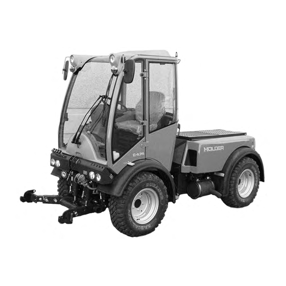
C 4.74 Description Views Vehicle Front left view 1 Turn signal, position light 2 Headlight, top 3 Driver’s cab 4 Dump body (dumper) 5 Rear of vehicle 6 Rear axle 7 Intake screen for oil cooler of traction drive 8 Intake screen for engine 9 Front axle 10 Upper link support... - Page 30 Description Vehicle Rear right view 1 Dump body 2 Flood light* 3 Support for rotating beacon 4 Driver’s cab 5 Front part of vehicle 6 Front axle 7 Intake screen for fresh air blower 8 Fuel filler neck 9 Rear axle 10 Battery isolating switch 11 Hydraulic quick...
- Page 31 C 4.74 Driver’s station Operating controls 1 Direction lever 2 Handle for LH side window 3 Steering wheel 4 Multifunctional display 5 Handle for RH side window 6 Turn signal and wiper control lever 7 Ignition lock 8 Light switch 9 Top headlight switch 10 Accelerator pedal 11 Brake pedal...
- Page 32 Description Right front controls console 1 Pressure gauge for hydraulic cushioning* 2 Main switch for implement hydraulics 3 Fine control knob for implement variable-displace- ment pump* 4 Switch for implement variable-displacement pump* 5 Switch for front PTO* 6 Joystick for working hydraulic system 7 Fine control knob for driving speed (in the driving speed ranges 3 and 4) 8 Driving program switch...
- Page 33 C 4.74 Right rear console controls 1 Fine control knob for driving speed (in the driving speed ranges 3 and 4) 2 Driving program button 3 Differential lock switch 4 Fan switch 5 Hydraulic oil temperature gauge 6 Fan reversing switch* 7 Air conditioning switch* 8 Hand throttle knob 9 Power socket...
- Page 34 Description Rear console controls 15 Diagnosis socket for working hydraulics 16 Diagnosis socket for traction hydraulics 17 Traction electronics warning light Hand throttle 1 Outer ring for fine control: - Turn clockwise to decrease rpm - Turn counter-clockwise to increase rpm 2 Inner knob for coarse adjustment - Pull out to increase rpm - Push in to decrease rpm...
- Page 35 C 4.74 Joystick 1 Pushbutton 1 for joystick level 1 2 Pushbutton 2 for joystick level 2 3 Pushbutton 3 for joystick level 3 4 Joystick (with no button pressed = joystick level 0) Pedals 1 Inching pedal 2 Brake pedal 3 Accelerator pedal 149 443 Description...
- Page 36 Description Steering wheel adjustment 1 Brake fluid reservoir 2 Steering wheel adjustment lever Heater until 04.2005 1 Heater control valve 2 Heating temperature label - horizontal - cooler - vertical - warmer C 4.74 Bild_C153 Bild_C147 149 443...
- Page 37 C 4.74 Multifunctional display, legend 1 Fuel gauge 2 Engine oil temperature gauge 3 Tachometer with mark- ings for PTO rpm 4 Hour meter 5 Digital speedometer Indicator lights: 6 Turn signal indicator 7 Turn signal indicator for 2nd trailer 8 Turn signal indicator for 1st trailer 9 High beam...
- Page 38 Description Controls in cabin at front top 1 Interior light 2 Loudspeaker Controls in cabin at front bottom 1 Washing water reservoir 2 Radio C 4.74 Bild_C149 Bild_C282 149 443...
- Page 39 C 4.74 Controls in cabin at rear 1 Roof hatch handle 2 Roof hatch Door controls 1 Door opener 149 443 Description Bild_C263 Bild_C156...
-
Page 40: Location Of Plates And Labels
(on fuel tank) 5 Chassis number (On front frame at right looking forward) 6 Wheel motor type plate C 4.74 GEBRÜDER HOLDER GMBH Typ : 204 EWG-Nr.: e1 - 74/150-0058 Identifizierungsnummer : 204000102 Zulässiges Gesamtgewicht: Zulässige Achslast vorn: Zulässige Achslast hinten: Technisch zulässige Anhängelast... - Page 41 C 4.74 Mounting instructions for licence plates Install the front licence plate (1) on the cover below the windshield wipers. First remove the cover before installing the licence plate. Install the rear license plate (2) at the rear below the left tail light.
- Page 42 Description Overview of options and variants (selection) Assembly Hydraulic sideshift Heating element for preheating oil (engine) Air conditioning Backrest extension, comfort Food light, rear Front power lift Rear power lift Trailer hitch, automatic Trailer hitch, manual Front PTO 1000 rpm Front PTO 540 rpm Rear PTO 540 rpm Hydraulic cushioning...
- Page 43 C 4.74 Assembly Flow divider, 1st circuit - Pump - Delivery capacity - Flow rate - Maximum pressure Flow divider, 2nd circuit - Pump - Delivery capacity - Flow rate - Maximum pressure Variable-displacement pump - Delivery capacity - Maximum pressure 149 443 Supplementary information Series pump...
- Page 44 3 Two ignition keys 4 Two door keys 5 2 tank cap keys 6 Two reducers for category I implements 7 Upper link with retaining pins 8 Key holder 9 Bio-pass for certification of filling with environment-friendly hydraulic oil C 4.74 Bild_C290...
-
Page 45: Taking Into Operation
C 4.74 Taking into operation Daily checks and services prior to taking into operation If damage or defects are found during the following checks, they must be eliminated before taking the vehicle into ser- vice. Do not operate the vehicle before proper repairs are carried out. - Page 46 Taking into operation Turn on the battery isolating switch NOTE The battery can be switched off completely with the removable key. Insert the key (1) into the battery isolating switch and turn it to the vertical position. The battery circuit is turned on. Check the engine oil level NOTE Check the engine oil level only when the ve-...
- Page 47 C 4.74 Check the trailer hitch (option) if required Check the trailer hitch for proper condition and opera- tion. Carry out the check according to the instructions in the section “Operating the trailer hitch“. Check the tire inflation pressure NOTE Your vehicle can be equipped with different types of tires.
- Page 48 Taking into operation Check the hydraulic oil level Raise the dump body (dumper). Retract all hydraulic cylinders. Check the oil level at the sight glass (1). The oil level must be at the centre of the sight glass. Top up oil as specified in the maintenance instruc- tions.
- Page 49 C 4.74 Filling fuel If necessary, read the fuel level (1) on the multifunc- tional display. CAUTION Danger of fire when handling fuels. Turn off the engine. Do not fill any fuels in the vicinity of naked flames, ignition sparks or hot en- gine parts.
- Page 50 Taking into operation Check the brake fluid level Check the brake fluid level at the brake fluid reservoir (1). The brake fluid level should be between the minimum and maximum marks on the reservoir. Top up brake fluid as specified in the maintenance instructions.
- Page 51 C 4.74 Adjust the driver’s seat with mechanical suspension DANGER Do not adjust the seat while driving. Risk of accidents! 1 Horizontal adjustment Raise the handle (1) and push the seat to the front or rear. Release the handle and allow the seat lock to engage.
- Page 52 Taking into operation Adjusting the driver’s seat with pneumatic suspen- sion 1 Backrest 2 Adjustment knob for lumbar padding 3 Backrest inclination 4 Weight adjustment 5 Horizontal cushioning 6 Horizontal adjustment DANGER Do not adjust the seat while driving. Risk of accidents! Adjust the seat so that all controls can be reached and operated safely.
- Page 53 C 4.74 Adjusting the driver’s weight Sit down on the driver’s seat. Pull the weight adjustment handle (4) up. NOTE An alarm sounds. The seat is automatically set to the weight of the driver; the alarm ceases. Release the lever. Adjusting the horizontal suspension Pull the horizontal suspension lever (5) back: Seat suspension is free in the horizontal direction.
- Page 54 Taking into operation Filling washing water NOTE The washing water reservoir for the windshield washer is located behind the driver’s seat. Open the filler cap (1) and add washing water into the reservoir (2). Filling quantity ... approx. 1.3 L Check the lights and rear view mirror Check the lights for proper operation.
-
Page 55: Starting The Engine
C 4.74 149 443 Taking into operation Starting the engine Notes on the engine before starting up DANGER Do not start or run the engine in enclosed spaces. Danger of poisoning through exhaust gases! Notes on starting CAUTION Before starting, make sure no-one is in the vicinity of the vehicle. - Page 56 Taking into operation Start the engine Set the forward/reverse selector switch (1) to the neutral position (centre). Fully depress the inching pedal (2). NOTE The engine can only be started if the pedal is fully depressed (starting safety switch). Set the hand throttle button (4) to idle (push in fully). Insert the ignition key and turn the preheat/starter switch (3) to position 1.
- Page 57 C 4.74 Turn the ignition key to position 2. The engine is being preheated. The preheating indica- tor (5) comes on. NOTE When starting at low temperatures, hold the ignition key longer (approx. 1 minute) in posi- tion 2. When the preheating indicator extinguishes, turn the ignition key to position 3 to start the engine.
- Page 58 Taking into operation Starting the engine with automatic preheating Starting procedure Turn the ignition key to position 1. The engine will be preheated. At temperatures below +10°C the yellow lamp (2) and the preheating indicator light (1) will come on. When the yellow lamp (2) extinguishes, turn the ignition key to position 3 to start the engine.
-
Page 59: Operation
C 4.74 Operation Before starting to drive When driving on public highways, observe the rules and regulations of the highway code. Driving safety rules • Drive the vehicle only from the driver’s station with the cab doors closed. • Always adjust your speed to the driving conditions and the load you are carrying. - Page 60 Operation Driving Driving with hydrostatic drive and digital electronics Start the engine. Preselect the direction of travel with the direction switch (1). Pull up the forward/reverse selector switch (1) and move it to the front or rear (forward or reverse). NOTE After starting the engine, the forward/reverse selector switch must be operated once if it...
- Page 61 C 4.74 Table of driving ranges Select the desired driving program with the driving program switch (2). The selected position is illuminat- You can select between 4 programs: Range 1 and 2 eg on-road travel Range 3 and 4 eg working 149 443 Operation Bild_C166...
- Page 62 Operation Table of driving programs• Position Symbol Range 0 STOP Range 1 Rabbit symbol Range 2 Turtle symbol Range 3 PTO symbol Range 4• • Snow blower symbol • The driving programs can be optimised for special operations by your Service, eg controlled constant driving speed •...
- Page 63 C 4.74 Selecting on-road travel (transport speed) The vehicle is stationary. Set the program switch (2) to range 1 or 2. NOTE The driving range can also be switched while driving at reduced speed. Release the parking brake. Depress the accelerator pedal for the desired speed. The vehicle starts and can be driven up to the maxi- mum speed of the chosen range.
- Page 64 Operation The vehicle is stationary. Set the fine control knob (1) to 0. Set the program switch (2) to range 3 or 4. Adjust the PTO rpm with the hand throttle (3). NOTE The engine speed must reach at least 1500 rpm as the control is only effective beginning at this speed.
- Page 65 C 4.74 Adjusting the fine control knob NOTE You can adjust the fine control knob (1) at any time while driving for fine and infinitely variable control of the driving speed. In position 0 the vehicle is stationary. When turned further clockwise, the vehicle starts driving and at the maximum scale position 11, the maximum speed of the driving range is achieved.
- Page 66 Operation Driving with SDS (Special Drive System)* For setting programs 1-3 with the program switch (2) see the operation section on pages 61 and 62. Driving program 4 (SDS) Set the program switch (2) to driving range 4. NOTE At this level the fine control knob (1) is not working.
- Page 67 C 4.74 Operating the inching pedal 7 Inching pedal 8 Accelerator pedal This function is active for all driving programs. NOTE The inching pedal allows driving speed to be reduced temporarily. ATTENTION If the inching pedal is floored, for example, for an EMERGENCY STOP, the vehicle will decelerate quickly.
- Page 68 Operation Engaging the differential lock NOTE With the differential lock you can improve trac- tion on soft, slippery ground. The engine speed should be over 1000 rpm during its use. You can engage the differential lock only briefly by toggling the switch momentarily. ATTENTION The differential lock may only be used when driving straight ahead.
-
Page 69: Two-Stage Steering
C 4.74 Steering The vehicle has a hydraulically-operated articulated steer- ing. The wheels also stay in track in curves so that imple- ments are guided without any lateral offset. Steering Turn the steering wheel (1) in the desired direction. The possible turning radii depend on the tires and track widths of your vehicle. - Page 70 Operation Brakes The service brake is a drum brake mounted in the front axle and it is actuated hydraulically. The parking brake is applied with the parking brake switch. Applying the service brake Depress the brake pedal (1). Applying the parking brake ATTENTION The parking brake is not intended to be used for braking while driving.
- Page 71 C 4.74 Releasing the parking brake Turn off the parking brake switch (2). The parking brake is released and the indicator light in the switch and the parking brake warning light (3) go out. If the parking brake warning light (3) in the multifunc- tional display comes on with the parking brake re- leased, there is too little pressure for releasing the parking brake in the pressure accumulator.
- Page 72 Operation Driving on slopes DANGER Driving on slopes is dangerous as the vehi- cle can tip over if the centre of gravity ex- ceeds the tip-over limit on an extreme slope. The following factors reduce the hazard: small or no load low driving speed low gradient low tire inflation pressure...
-
Page 73: Special Operating Instructions
C 4.74 Special operating instructions Stationary operation The vehicle can be used for stationary operation, for example, to drive a water pump via the PTO shaft. ATTENTION Place the vehicle n level ground in both di- rections. Attach the stationary equipment to the PTO shaft (1). Set the program switch to 0. - Page 74 Special operating instructions Adjusting the track width You can adjust the track width of the vehicle by mounting the wheels inside out. DANGER Observe the safety notes on a safe shutdown and jacking up for the wheel change in the maintenance instructions.
- Page 75 C 4.74 Operation in winter Oil preheating* Before starting the engine at temperatures below -20°C, turn on the heating element* to preheat the oil. Connect the preheating system plug to a 230 VAC source. Observe the operating instructions of the battery manufacturer. Winter diesel fuel Whenever temperatures fall below 0°C, use winter diesel or super diesel fuel or additives recommended in the mainte-...
-
Page 77: Operating The Implements
C 4.74 Operating the implements We have tested and approved a large number of possible implements for use with this vehicle. Only implements with the CE symbol may be used. We recommend contacting our customer service before installing special equipment. Possible implements For example for: vineyards and orchards... - Page 78 Operating the implements Additional information on implements Do not exceed the permissible total weight, the permissible axle loads and tire carrying capacities of the vehicle when installing im- plements on the front and rear 3-point lift. The front axle of the vehicle must always be loaded with at least 20 % of the vehicle’s kerb weight.
- Page 79 Enter the calculated minimum ballasting required for the rear of the vehicle in the table. (Value X for Holder vehicle 0.25 4-wheel) 3) Calculation of the actual front axle load T (If the minimum front ballasting (G the front implement (G...
- Page 80 Operating the implements 6) Tire carrying capacity Enter the double value (two tires) of the permissible tire carrying capacity (eg see tire manufacturer documentation) in the table. Actual Calculated Weight Minimum ballast at front/rear Total weight Front axle Rear axle The minimum ballasting must be mounted on the tractor either as attachment or ballast weight! The calculated weights must be lower than/equal to (≤) the permissible weights! Specified Permissible...
- Page 81 C 4.74 Attaching implements The various implements are attached to the front or rear power lift*. There are 2 different fastening categories: Category I Pin diameter 22 mm Category II Pin diameter 28 mm The vehicle can be adjusted to both categories by adjusting the pintle hook bars and providing the pintle hooks with or without reducer sleeves.
- Page 82 Operating the implements Adjusting the pintle hooks and pintle hook bars You can adjust the pintle hooks laterally and longitudinally. Measure the stand-off of the pins on your implement. Loosen the clamping screws (6) on both sides. Slide the pintle hooks laterally until the required distance is reached.
- Page 83 C 4.74 Adjusting the upper link The upper link can be secured at different holes. The re- quired height depends on your implement (for a better adap- tation of the equipment, to increase the lifting force and depending on the lifting height). Upper hole •...
- Page 84 Operating the implements Connecting hydraulic lines ATTENTION The hydraulic couplings on the vehicle must not carry any pressure before the connection is made. The couplings on the vehicle and the hydraulic hoses must be clean. NOTE Each implement has different functions and hydraulic lines to the control unit.
- Page 85 C 4.74 Installing the cardan shafts Only use shafts suitable and intended for the implement. These shafts are supplied with the implement. The length the of the shaft must be adjusted before the first installa- tion. In case of doubt, please contact our after-sales serv- ice.
- Page 86 Operating the implements Operating the joystick 1 Pushbutton 1 for joystick level 1 2 Pushbutton 2 for joystick level 2 3 Pushbutton 3 for joystick level 3 4 Joystick (joystick level 0 without pushbutton opera- tion) 5 Main switch for working hydraulic system NOTE The joystick controls those functions of the implements which are connected to the front...
- Page 87 C 4.74 Joystick operation (Proportional, for sensitive operation). Joystick direction Longitudinally (forward / back) Joystick level 0 Front power lift Y0 (without button) Forward: lowering Back: Float position on keyboard Joystick level 1 Dumper / rear power lift * Y1 (with button 1 pressed) Forward: lowering Back:...
- Page 88 Operating the implements Operating the front power lift The following movements are possible: Turn on the main switch (5) for working hydraulics. Push the joystick (4) forward. • The front power lift (implement) is lowered. You can stop the movement by releasing the joystick. Pull the joystick (4) back.
- Page 89 C 4.74 Operating the front power lift with keyboard The following movements are possible: Turn on the main switch (3) for working hydraulics. Keep button (4) depressed for about 1 second. The red LEDs (5 and 2) come on for about 5 seconds. •...
- Page 90 Operating the implements Switching the front power lift to double-acting The front power lift can be switched from single-acting to double-acting. To switch to double-acting press button (5). The red LED (6) goes off. To switch to single-acting toggle button (5). The red LED (6) comes on.
- Page 91 C 4.74 Operating the sideshift with the keyboard Keep button (4) depressed. • The front power lift pivots to the right. You can stop the movement by releasing the button. Keep button (3) depressed. • The front power lift pivots to the left. Press button (1) for about 1 second.
- Page 92 Operating the implements External operation of the front power lift The front power lift can be operated from outside the cab. ATTENTION When leaving the cab, set the forward/reverse selector switch to neutral and apply the park- ing brake to secure the vehicle against roll- ing.
- Page 93 C 4.74 Flow limiter for joystick Button for individual flow limitation for each individual joystick function. Turn on the main switch for working hydraulics. The lifting and lowering speed of the power lift can be stored individually with the flow limitation. Operate the joystick (4) until the desired cylinder speed is reached, then press button (1).
- Page 94 Operating the implements Operating the rear power lift* The following movements are possible: Turn on the main switch for working hydraulics. Set the switch lever (1) at the rear to the position „Rear Power Lift“. To raise the lift, press button (2) and pull the joystick (3) back.
- Page 95 C 4.74 External operation of the rear power lift* The rear power lift can be operated from outside the cab. ATTENTION When leaving the cab, set the forward/reverse selector switch to neutral and apply the park- ing brake to secure the vehicle against roll- ing.
- Page 96 Operating the implements Operating the hydraulic couplings 1 Pushbutton 1 for joystick level 1 2 Pushbutton 2 for joystick level 2 3 Pushbutton 3 for joystick level 3 4 Joystick (joystick level 0 without pushbutton opera- tion) 5 Main switch for working hydraulic system NOTE The joystick controls those functions of the implements which are connected to the front...
- Page 97 C 4.74 Operating the green hydraulic couplings* Push the joystick (4) to the left or right. • The green front right hydraulic couplings will be supplied with oil. You can stop the movement by releasing the joystick. The float position is turned on with the keyboard. To turn it on, press button (7).
- Page 98 Operating the implements Turning on the front PTO DANGER Before turning on the PTO, make sure no- one is standing close enough to the vehicle and the driven implement to be hurt. ATTENTION Check the mounting angle of the cardan shaft. Turn on the PTO at low speed, then increase the speed.
- Page 99 C 4.74 Turning on the rear PTO* DANGER Before turning on the PTO, make sure no- one is standing close enough to the vehicle and the driven implement to be hurt. ATTENTION Check the mounting angle of the cardan shaft. Turn on the PTO at low speed, then increase the speed.
- Page 100 Operating the implements Operating the hydraulic cushioning* (front power lift) The hydraulic cushioning allows the ground pressure of the implement to be decreased steplessly and to increase the front axle loading. This improves the climbing ability. Press button (5). LED (7) will come on. The electronic pressure sensor (2) with a digital display al- ways indicates the current pressure of the front power lift when float position is turned off.
- Page 101 C 4.74 NOTE A cushioning pressure of less than 30 bar (light implements) will result in too many con- trol operations as the accumulator can not act. Operation with implement cushioning NOTE If the implement adapts to uneven ground with delay, reduce the cushioning pressure or HYS.1.
- Page 102 If a new or unknown implement is to be in- stalled, the wiring harness for implement cod- ing 204-80-72 must be used. The correct cod- ing must be established in consultation with the implement manufacturer and Holder. * Option C 4.74 Bild_C279...
- Page 103 C 4.74 ATTENTION Turn on the starting safety switch (6) only at low engine speed. Set the rotary knob (5) to 0. Release the lock at the starting safety switch (6) and depress the switch. The indicator in the switch comes ATTENTION After the speed of the motor was raised, the oil flow may only be raised slowly.
- Page 104 Operating the implements NOTE The implement variable-displacement pump attempts to maintain the oil flow specified by the coded plug and potentiometer, even when the engine speed is reduced. The oil flow is only reduced at lower rpm when the maximum swash angle of the pump is reached (see diagram).
- Page 105 C 4.74 Operating the hydraulic dumper With the hydraulic dumper it is possible to lift the dump body fast and easily. The dumper tilts loading platform* to the rear. Start the engine. Switch lever for device to be operated: Put the switch lever(1) at the rear to the “dumper“ position (side position).
- Page 106 Operating the implements Operating priority flow valve I* Priority flow valve I is used to drive the servo motor in an implement with a variable hydraulic power demand, for ex- ample, salt spreader, hedge cutter, etc. The working speed can be set independently of the vehicle engine speed. The priority flow valve is supplied by the (standard) working pump and operated from the driver’s station.
- Page 107 C 4.74 Select the desired engine speed with the hand throt- tle. Set the rotary knob (3) to the operating speed required for the implement. Turning clockwise increases, turning counterclock- wise lowers the speed. The servo motor in the implement is supplied with an oil flow of 0 to 25 litres/min.
- Page 108 Operating the implements Operating priority flow valve II up to 04.06 Priority flow valve II is used to drive the servo motor in an implement with a variable hydraulic power demand, for ex- ample, salt spreader, hedge cutter, etc. The working speed can be set independently of the vehicle engine speed.
- Page 109 C 4.74 Select the desired engine speed with the hand throt- tle. Go to the rear of the vehicle and adjust the hand wheel (5) of the priority flow valve to the working speed required for the implement. Turning clockwise increases, turning counterclock- wise lowers the speed.
- Page 110 Operating the implements Operating priority flow valve II from 05.06 The priority flow valve II is used to drive a servo motor in an implement with a variable hydraulic power demand, eg salt spreader, hedge clipper, etc. The operating speed can be set independent of the engine speed of the vehicle.
- Page 111 C 4.74 Select the desired engine speed with the hand throt- tle. Set the rotary knob (3) to the operating speed required for the implement. Turning clockwise increases the speed, turning anticlockwise lowers it. The servo motor in the implement is supplied with an oil flow of 0 to 25 litres/min.
-
Page 113: Other Activities
C 4.74 Other activities Operating the driver’s cab Operating the roof hatch Opening the roof hatch Press the button (2) on the side of the handle. Push the handle (1) up to open the roof hatch at the rear. Removing the roof hatch NOTE The roof hatch can be used as an emergency exit in case of danger. - Page 114 Other activities Turning on windshield wiper/washer NOTE The vehicle is provided with a front wiper. A washer system is also installed. The washer system draws its water from the washing water reservoir at the front left-hand side in the cabin. Front windshield wiper/washer Turn the rotary switch (1) for the front windshield wiper to stage J.
- Page 115 C 4.74 Lights Turning on and operating the lights NOTE Turn the preheat/starter switch to position 1. Set the light switch (2) to position 1. The front clearance lights (3,6) and the tail lights (10,14) (parking light) are switched on. The clearance light indicator (3) in the multifunctional display will come on.
- Page 116 Other activities Right headlight, dip beam 2 Right headlight, high beam 3 Turn signal and clearance light, right 4 Headlight, top 5 Headlight, top 6 Turn signal and clearance light, left 7 Left headlight, high beam 8 Left headlight, dip beam 9 Stop light 10 Tail light Turn signal light, left...
- Page 117 C 4.74 Turning on the top headlights NOTE If front implements are installed and the bot- tom headlights are hidden, you may turn on the upper headlights. Turn on the toggle switch for the top headlights (2). The top headlights (4, 5) will go on. NOTE The high beam and headlight flasher func- tions are only available for the bottom head...
- Page 118 Other activities Operating the hazard warning flasher system Turn on the hazard warning flasher switch (1) to let all the turn signal lights flash. Turning on the rotating beacon* NOTE The rotating beacon may only be turned on if the vehicle is used for applications in public traffic areas.
- Page 119 C 4.74 Turning on the flood light* NOTE The flood light must not be used in the public traffic area. Turn the flood light switch (1) on. The flood light (2) will be on. Interior light Turning on the interior light NOTE There is an interior light on the left and right in the cabin roof.
- Page 120 Other activities Radio* and loudspeakers* Operating the radio NOTE There is a separate operating manual for the radio. Please observe the instructions in this manual for operation of the radio. The loudspeakers are installed at the front in the roof of the cabin.
- Page 121 C 4.74 Heater Heating and ventilating Turning on the heater NOTE The cabin heater is heated by the engine cooling oil. To heat the cabin, turn the rotary knob (1) clockwise. You may select any intermediate position. Turn the knob CCW to reduce the heating capacity, CW to increase it.
- Page 122 Other activities Turning on the ventilation To ventilate the cabin turn on the fresh air blower switch (3). NOTE The fresh air blower has 2 speeds. Position 1 slow Position 2 fast There are several air vent nozzles (4, 5) fitted in the cabin: 1 adjustable nozzle (4) at the bottom front right in the foot room 13 air slots (5) in the dash for front and side windows...
-
Page 123: Air Conditioning
C 4.74 Air conditioning Operating the air conditioning* NOTE A separate operating manual is supplied for the air conditioning. Please observe the instructions in this manual for operation of the A/C. Air conditioning* 1 Switch for 2-speed blower 2 Blower reversing switch 3 On/off switch 4 Temperature control 5 Air slots... - Page 124 Other activities Fuses CAUTION Before carrying out any work on the electri- cal equipment, for example, replacing the fuses, always turn the battery isolating switch off. Vehicle fuses NOTE The fuses for the vehicle are installed below the console at the right-hand side. Open the flap for access.
- Page 125 C 4.74 F11 Radio 30/interior light F12 Air conditioner F13 2-pin socket/electric seat adjuster 15 F14 Heatable external mirrors F15 Stop light F16 Headlight flasher/0-position wiper/washer F17 Cigarette lighter/rear cab flood light F18 Deutz shutoff solenoid F19 Cooling air blower/heater/A/C F20 Spare F21 Radio 15 F22 Turn signal light...
-
Page 127: Taking Out Of Operation
C 4.74 Taking out of operation Leaving the vehicle Stopping Lower the implement completely. Engage the parking brake. Fully push in the hand throttle button (2) (idle posi- tion). Set the forward/reverse selector switch to 0. Set the driving program switch (1) to 0. ATTENTION If the engine is overheated (engine tempera- ture gauge (3) in the red field), let the engine... - Page 128 Taking out of operation Shutdown ATTENTION If the vehicle is parked on gradients, it must be secured against rolling with chocks. If equipped with a hydrostatic drive, also use chocks to secure the vehicle. Turn the ignition key (3) back to 0. The engine is shut down.
-
Page 129: Trailers, Towing
C 4.74 Trailers, towing Your vehicle can tow the following trailers: Table of trailers Type of Trailer Single axle trailer Single and multiple axle trailer Single axle tailer Multiple axle trailer Trailer The following trailer combinations are allowed: 1 Vehicle with single-axle trailer with brakes or without brakes. 2 Vehicle plus single-axle trailer with brake or without brake plus two-axle trailer with override brake. - Page 130 Trailers, towing Operating the trailer hitch manually, attaching trailers Put the trailer hitch (5) in the two lower holes provided on the adjustment rail (2) with the fastening pin (3) and secure the pins with the retaining clips. Bearing load ATTENTION The bearing load must be at least 25 kg (4 % of the trailer load), while the maximum bear-...
- Page 131 C 4.74 Operating the trailer hitch automatically, attaching trailers Put the trailer hitch (6) in the two lower holes provided on the adjusting rail (3) with the fastening pin (4) and secure the pins with the retaining clips. Bearing load ATTENTION: The bearing load must be at least 25 kg (4 % of the trailer load), while the maximum bearing load must not exceed 600...
- Page 132 Trailers, towing Driving with trailers Turn the driving program switch (1) to range 1 or 2. The maximum drawbar pull is achieved in range 2. Drive the vehicle as described in the section on driving. DANGER If a trailer not requiring a permit is attached, the driving speed is limited to 25 km/h.
-
Page 133: Transport, Hoisting, Towing
C 4.74 Transport, hoisting, towing Instructions for transport Drive the vehicle on the hauling vehicle. Shut down the vehicle as described in section “Leav- ing the Vehicle“. Secure the vehicle against rolling with chocks at the wheels and, if needed, with wood blocks at the sides to prevent it from sliding. - Page 134 Transport, hoisting, towing Towing instructions Your vehicle can be towed if disabled due to damage. Use the upper link support at the front at the driver’s cab for towing. DANGER The towing vehicle must have sufficient trac- tive and braking force for the towed load with- out brakes.
- Page 135 C 4.74 ATTENTION If the parking brake can not be released due to a lack of pressure in the accumulator and pressure can not be built up on account of a failure of the engine or hydraulic system, re- move the brake cable on the hydraulic cylin- der so that the vehicle can be towed.
-
Page 137: Indicators, Adjustments
C 4.74 149 443 Operating instructions Indicators, adjustments Adjusting the speedometer The adjustment of the speedometer in the multifunctional display is required when changing from large to smaller tires and vice versa. Please refer to the maintenance instructions for the adjust- ment of the speedometer. -
Page 139: Troubleshooting Guide
C 4.74 Troubleshooting guide The following tables list problems and their possible causes. If you can not carry out the remedy yourself, please con- tact an authorized workshop or our customer service. Test and Control Box BB3 or the Bodem PC software, with which further troubleshooting/diagnostics are possible, are available as an option. - Page 140 Troubleshooting guide Problem Low tractive force No forward and reverse travel Cause Fault in boost or high-pressure system Check suction filter in return line Drive of variable-displacement pumps defective Forward/reverse selector switch in neutral Machine started with preselected direction of travel No power supplied to the electronics Electrical connection to the variable pump interrupted...
- Page 141 C 4.74 Problem No forward and reverse travel No forward and reverse travel or only one direction No fast-slow available Vehicle drives in one direction only 149 443 Cause Forward/reverse selector switch defective or bad contact Drive program switch at 0 Fault in boost or high pressure system Check boost pressure in hydraulic Driving program switch defective Hydraulic valve for slow/fast defective...
- Page 142 Troubleshooting guide Problem No maximum speed Does not remain stationary with inching pedal depressed Inching pedal not functioning (warning light flashes) Machine does not stop without depressing accelerator in driving program 1 or 2 Cause Diesel engine does not attain maximum speed Inching pedal not at maximum speed Variable-displacement pump not at full...
- Page 143 C 4.74 Problem Differential lock does not operate Parking brake can not be released 149 443 Cause Fuse blown or bad contact Switch defective Hydraulic valve for differential lock defective or no pressure exists No power Differential lock on wheel motor too hard to operate Switch defective Too little pressure in accumulator...
- Page 144 Troubleshooting guide Problems in the hydraulic system and steer- NOTE These notes only apply for valve arrange- ments conforming to our circuit diagrams or approved by Bucher Hydraulics. Problem Power lift or hydraulic cylinders not lifting. No pressure build-up noticeable (steering working normally).
- Page 145 C 4.74 Problem Hydraulic oil heats too quickly, system works against excess pressure. (engine under load) Hydraulic oil foams Hydraulic system working too slowly, accompanied by whistling noise Steering not working Lost steering motion when steering direction is changed rapidly 149 443 Cause Cylinder at limit stop...
- Page 146 Troubleshooting guide Problems in the working hydraulic system The diagnostic unit OPUS and PC software are available as options with which further troubleshooting/diagnosis/ad- justment of the electronics in the working hydraulic system is possible. NOTE These notes only apply for valve arrange- ments conforming to our circuit diagrams or approved by Bucher Hydraulics.
- Page 147 C 4.74 Problem Joystick inoperative Keyboard inoperative Many joystick and keyboard functions malfunctioning simultaneously Functions too slow or too fast 4th control level on the joystick malfunctioning Joystick or keyboard malfunction 149 443 Cause Joystick disabled Buttons defective Mechanical or electric defect Power supply cut off (3 separate positive cables, pins 05, 23, 34...
- Page 148 Troubleshooting guide Problem Many malfunctions Buttons respond too slowly Buttons “locked” instead of “active” Hydraulic implement cushioning inoperative Implement cushioning pulsing a lot Cause Some parameters out of adjustment Load “default settings” with Opus or Set incorrectly to “slow” Set incorrectly Turned off Electronic pressure sensor defective Specified pressure too low...
- Page 149 C 4.74 Problem Directional control valve leaky No pressure build-up Strong oil flow fluctuation in flow divider I or oil flow too low Troubleshooting is also possible with Opus (Order No. 204- 80-70) or the PC software in the menu •...
-
Page 151: General Remarks On Maintenance
Detach the double guarantee card, have it filled in by your dealer and send it signed by the customer directly to: Holder Industries GmbH P. O. Box 15 55 72545 Metzingen/Württ. The warranty and product liability will only be maintained if the maintenance services and inspections are carried out regularly. - Page 152 General remarks on maintenance Service The following services were carried out: In the maintenance table below you can enter the properly car- ried-out services and inspections and have them confirmed. (These entries are required to keep your warranty claims intact): Service Hours of Interval...
-
Page 153: Handling Fuels And Lubricants
C 4.74 Handling fuels and lubricants • Fuels and oils must always be handled properly and as specified by the manufacturer. • Fuels and oils may only be stored in approved contain- ers at specified places of storage. They can be inflam- mable, therefore do not allow them to come in contact with hot objects or with naked flames. - Page 154 • The mounting of tires requires sufficient knowledge and special mounting tools. • Only use genuine HOLDER replacement parts! Use the parts in the list of maintenance parts in the chapter entitled “Maintenance data“. • The vehicle and the implement must be checked for road worthiness and operating safety before taking it into operation and after servicing or repairs.
- Page 155 C 4.74 Work on the electrical system Before performing any services on the electrical equipment, switch off power with the battery isolating switch (1). The switch must be horizontal, the toggle removed. CAUTION Disconnect the battery ground lead (2). Do not place any metal parts on the battery terminals. Risk of short circuit! 149 443 General remarks on maintenance...
-
Page 156: Jack Lift Points
General remarks on maintenance Jack lift points Jacking up DANGER When using the jack, be sure the vehicle is shut down and secured against rolling (chocks)! The vehicle may only be jacked up at the shown locations (1 and 2). DANGER The weight to be lifted should not exceed the permissible load capacity of the jack. - Page 157 C 4.74 Securing the dump body (loading platform*) For all services requiring the dump body (loading platform*) to be raised, secure it against accidental lowering. Turn the changeover lever (1) to the right (hydraulic lock). NOTE To lower it, return the changeover lever (1) to the left.
-
Page 158: Tilting The Cab
General remarks on maintenance Tilting the cab The cabin can be tilted for repairs and servicing. ATTENTION Raise the cabin carefully. Remove the front fender by removing the socket head screw and pushing the roller back. Remove the nuts (1) and retaining plate at the rear of the cabin. -
Page 159: Maintenance Schedule
C 4.74 Maintenance schedule Maintenance during the first period of operation Interval Maintenance after the first 50 hours Maintenance after the first 500 hours The checks and services specified below must be carried out when the stated number of service hours is reached. The checks and services of the lower intervals must be carried out at the same time. - Page 160 Maintenance schedule Interval Maintenance as required Periodic maintenance Maintenance every 125 hours Maintenance every 250 hours Maintenance every 500 hours Service or check Adjust the speedometer Check the air cleaner system Check the cooling system Clean cooling system Check the battery and cable terminals Check hydraulic oil level, see page 48 Check the high pressure hoses Check the steering cylinder and orbitrol...
- Page 161 C 4.74 Periodic maintenance Interval Maintenance every 1000 hours Maintenance every 1500 hours Maintenance every 3000 hours Annual maintenance 149 443 Maintenance schedule Checks and services Check engine valve clearances Check the battery Check V-belt tension and condition Change the fuel filter Clean/replace the fuel pump strainer Lubricate the cardan joint nipples Change hydraulic oil for traction and working hydraulics...
-
Page 163: Maintenance During The First Period Of Operation
C 4.74 Maintenance during the first period of operation The following checks and services are due during the first period of operation: Maintenance after the first 50 hours Maintenance after the first 500 hours Maintenance after the first 50 hours Check the engine for leaks Raise the dump body (loading platform*) and secure it against accidental lowering. -
Page 165: Maintenance As Required
C 4.74 Maintenance as required Adjusting the speedometer The adjustment of the speedometer in the multifunctional display is required when changing from large to smaller tires and vice versa. Carefully pull the multifunctional display (1) out at the right and left side and rotate it. Remove the cover from the combination switch (2) on the back. - Page 166 Maintenance as required Serial number 05110015.01 on multifunction display until approx. 04.07 Tire size 340/65 R18 422-31-06 & 422-31-07 275/80 R18 4131-14 & 422-31-2 36x13.50-15 204-31-03 10.5-18 MPT 4131-22 & 422-31-3 320/65 R18 422-31-4 & 422-31-05 425/55 R17 204-31-02 33x12.50 R15 4131-23 33x15.5-15 4131-18...
- Page 167 C 4.74 Serial number 05110015.02 on multifunction display from approx. 04.07 Tire size 340/65 R18 422-31-06 u. 422-31-07 280/80 R18 422-31-11 u. 422-31-12 275/80 R18 4131-14 u. 422-31-2 36x13.50-15 204-31-03 10.5-18 MPT 4131-22 u. 422-31-3 400/60-15.5 422-31-08 320/65 R18 422-31-4 u. 422-31-05 425/55 R17 204-31-02 33x12.50 R15...
- Page 168 Maintenance as required Check the air cleaner system The filter cartridge must be serviced when the flow resist- ance of the filter is highest due to the restriction of the ele- ment. This is indicated by the sounding of an alarm. Stop the engine.
-
Page 169: Periodic Maintenance
C 4.74 Periodic maintenance Maintenance every 125 hours ATTENTION Carry out the checks and services only with the engine turned off. Check the cooling system Inspect the cooling fins and oil cooler for the accumu- lation of dirt. Clean the cooling system Clean with compressed air Raise the dump body (loading platform*) and secure it against accidental lowering. - Page 170 Maintenance every 125 hours Check the battery and cable terminals CAUTION When working on the electrical equipment, always disconnect the ground lead (1) at the battery. Check the battery acid level and inspect the battery for leaks. Observe the information of the battery manufacturer.
- Page 171 C 4.74 Check the steering cylinder and orbitrol Check the steering cylinder and orbitrol for damage and leaks. Have damaged or leaky parts replaced by an author- ized workshop. Check the brake fluid level for the foot brake Check the brake fluid reservoir for the foot brake (1). The brake fluid level must be between the markings.
- Page 172 Maintenance every 125 hours Check the braking system DANGER Do not operate the vehicle with a defective braking system. Apply the parking brake. Set the vehicle to driving range 1 or 2 and start driving slowly. A noticeable resistance should be felt when starting to drive and an alarm should sound.
- Page 173 C 4.74 Grease the vehicle Grease all moving parts lightly. Lubricate the grease nipples (1) according to the lubrication chart. Only use recommended grease. ATTENTION Lubricate the grease nip- ples (2) only every 1000 hours. (Do not inject too much grease to prevent damage to the seal.) 149 443 Maintenance every 125 hours...
- Page 174 Maintenance every 125 hours Tighten nuts and bolts Tighten the pump, axle and engine fasteners. Tighten fasteners to the specified torque according to tables in the maintenance data. Tighten wheel nuts Tighten all wheel nuts on the front and rear wheels (1 and 2).
- Page 175 C 4.74 Clean the fresh air filter Remove the fastening screws (1). Remove the filter cover (2) and take out the filter element. Clean the filter element or replace it. NOTE A charcoal filter* is available for applications such as spraying insecticides, etc. Install the filter element and refit the filter cover.
-
Page 177: Maintenance Every 500 Hours
C 4.74 Maintenance every 250 hours Change the engine oil Run the engine warm to operating temperature. Set the heating control to high. Place the vehicle on level ground and turn off the engine. Place a suitable oil pan underneath the engine. CAUTION Danger of scalding when draining hot engine oil. - Page 178 Maintenance every 250 hours Change the engine oil filter See the operating instructions of the engine manufacturer. Drain the engine oil. Remove the filter element (1) with a filter wrench. ATTENTION Observe the instructions for handling fuels and lubricants. Clean the sealing surface of the filter element mount- ing base.
-
Page 179: Maintenance Every 500 Hours
C 4.74 Check the heating system Turn the rotary knob (2) CCW to the OFF position. Run the engine warm. Turn the rotary knob (2) CW to the ON position. Set the heating blower switch (1) to stage 2. Warm air should flow out of the heating nozzles. -
Page 181: Maintenance Every 1000 Hours
C 4.74 Maintenance every 1000 hours Check engine valve clearances See the operating instructions of the engine manufacturer. Check the battery CAUTION For the sake of your safety, observe the fol- lowing instructions. The battery contains dissolved sulphuric acid, which is poisonous and caustic. When working with battery acid, wear per- sonal protective equipment (protective apron, protective gloves) and eye protectors. - Page 182 Maintenance every 1000 hours Check V-belt tension and condition See the operating instructions of the engine manufacturer. CAUTION Service V-belts only with the engine station- ary. Inspect V-belts for cracks and tears over the entire length. Replace damaged V-belts. Using thumb pressure, check if the V-belt can not be depressed more than 10 - 15 mm.
- Page 183 C 4.74 Change the fuel filter and fuel prefilter See the operating instructions of the engine manufacturer. Remove the fuel filter cartridge with a filter wrench. ATTENTION Observe the instructions for handling fuels and lubricants. Clean the sealing surface of the filter base. Coat the new gasket with oil.
- Page 184 Maintenance every 1000 hours Lubricating the cardan joint nipples Steer the vehicle as far as steering stop. CAUTION Carry out services in the articulated joint area only with the engine shut off. Move centre cardan shaft (1) with starter until grease nipples are easily accessible.
-
Page 185: Maintenance Every 1500 Hours
C 4.74 Maintenance every 1500 hours Change hydraulic oil for traction and working hydrau- lic system NOTE Change the hydraulic oil while at operating temperature. Place the vehicle on level ground. Raise the dump body. CAUTION Secure the dump body (loading platform)* against accidental lowering. - Page 186 Maintenance every 1500 hours Change the filter for the traction and working hydraulics return line. Remove the filter cover (1). Pull the filter element out. ATTENTION Observe the instructions for handling fuels and lubricants. Install a new filter element in filter housing. Refitting is the reverse of removal.
- Page 187 C 4.74 Clean: Wash the straining star filter with clean diesel fuel. Change: Remove the straining star filter from the filter housing with a 24mm open-ended wrench. Fit a new toroidal sealing ring on the new filter and screw it on to the filter housing. Refitting is the reverse of removal.
-
Page 189: Maintenance Every 3000 Hours
C 4.74 Maintenance every 3000 hours Check the injection nozzles ATTENTION This work may only be carried out by an au- thorized workshop. Clean the injection nozzles. Check the injection nozzles with a test pressure of 250 +8 bar. Change the toothed belt Change every 3000 hours or 5 years maximum. -
Page 191: Annual Maintenance
C 4.74 Annual maintenance Change the brake fluid of the foot brake ATTENTION This work may only be carried out by an au- thorized workshop. 149 443 Operating instructions... -
Page 193: Laying Up
C 4.74 Laying up If the vehicle is not going to be in service for over 2 months, for example for operational reasons, it must be placed in a well-ventilated, clean and dry room and the following meas- ures must be carried out. Clean the vehicle thoroughly. - Page 194 Drive hydraulics, gearshift, steering. Brake (service brake, parking brake) Working hydraulics, functions and work movements. If the vehicle is to be laid up for a longer period, please contact your HOLDER Service for further measures. C 4.74 149 443...
-
Page 195: Fuel And Lubricant Recommendations
C 4.74 Fuel and lubricant recommendations Recommended hydraulic and gear oils Manufacturer ISO viscosity class HLP (HM) HV AGIP ARAL AVIA BECHEM BAYWA BUCHER & CIE ESSO TOTAL TOTAL TOTAL FUCHS FUCHS OEST SHELL VALVOLINE 149 443 Operating instructions Hydraulic oils HE oils (hydr. - Page 196 Fuel and lubricant recommendations Recommended engine oils and greases The following oil brands conform to US Military Specifica- tion MIL-L-2104C or to API quality CD/SF and ACEA. Manufacturer AGIP AGIP ARAL ARAL BAYWA BAYWA BP OIL International CASTROL GmbH CASTROL GmbH CHEVRON ESSO FUCHS...
- Page 197 C 4.74 Recommended engine oils and lubricants, continued Manufacturer Lubricating oil type MOBIL OEL Mobil Delvac 1 SHC MOBIL OEL Mobil Delvac 1 MOBIL OEL Mobil Delvac XHP Ultra SHELL International SHELL Myrina TX/ SHELL Rimula Ultra SHELL International SHELL Myrina TX/ SHELL Rimula Ultra Schmierölraffinerie Wintershall TFG...
-
Page 199: Maintenance Data
C 4.74 Maintenance data Filling quantities Engine oil Incl. filter 0.5 litres Incl. heater 0.75 litres Hydraulic oil tank for traction and working hydraulics, hydraulic oil* Initial filling (depending on equipment) Front PTO gear Rear PTO gear Brake fluid for footbrake Fuel tank, diesel fuel Washer reservoir * NOTE... - Page 200 Maintenance data Tightening torques Hexagon screws and studs Screw quality 8.8 Screw quality 10.9 Hydraulic system, wheels M10 hex head screws (orbitrol to steering supports) Clamping screws for hydraulic control valves Wheel fasteners 25 Nm 35 Nm Torque Engine Cylinder head cover 40 Nm Rocker arm setscrew 16 Nm...
- Page 201 C 4.74 List of replacement parts Description Drain plug seal Engine oil filter Fuel filter Fuel prefilter Cylinder head cover gasket Air cleaner element V-belt for KHD fan Toothed belt repair kit Return line filter (working and traction hydraulics) Suction filter (working hydraulics) Toroidal sealing ring 64x3 Filter element (fresh air filter for cabin) Ventilation filter with active charcoal (fresh air filter for cabin)
- Page 202 Maintenance data Bulbs 12 V Lights Headlight, dip beam H7 Headlight, high beam H7 Turn signal light, front Turn signal light, rear Tail light Licence plate light Stop light Back-up light Rating Lights 55 W Flood light, front top H7 55 W Flood light, rear H3 21 W...
- Page 203 C 4.74 Engine specifications Manufacturer Model Type Mode of operation Cooling Injection mode Number of cylinders Cylinder bore Stroke Cubic capacity Compression ratio Compression Charging pressure Valve clearances with engine cold Fuel consumption Air filter Lubrication system Lubricating oil consumption Oil filter Oil pressure at 900 rpm Rated speed...
- Page 204 Maintenance data Fuel system C 4.74 Injection pump Motorpal individual withdrawable element- type calibrated pump Governor Governor integrated in the front cover Injection nozzle 5-hole nozzle Injection pressure 850 bar Start of fuel injection 0°+/-0.5° BTDC Drive pump Hydrostatic drive Axial piston pump Type A4 VG40 EP1D1 / A4 VG40 EP1D1 Operating pressure 420 bar...
-
Page 205: Alphabetical Index
C 4.74 Alphabetical index Accessories ...42 Additional information on implements ... 76 Adjust the driver’s seat with mechanical suspension ...49 Adjust the steering wheel ... 48 Adjusting the backrest inclination ... 50 Adjusting the driver’s seat with pneumatic suspension ..50 Adjusting the driver’s weight ...51 Adjusting the fine control knob ...63 Adjusting the horizontal suspension ...51... - Page 206 Alphabetical index Change the filter for the traction and working hydraulics return line ... 184 Change the fuel filter and fuel prefilter ... 181 Change the toothed belt ... 187 Changing the direction of travel ...65 Check and clean the cooler and debris screens ...43 Check engine valve clearances ...
- Page 207 C 4.74 Date of issue and manual version ... 2 Description ...27 Development ... 1 Dimensional drawing ...15 Disengaging the differential lock ...66 Door controls ...37 Driver’s licence ... 7 Driver’s licence classes ... 7 Driver’s station ...29 Driving ...58 Driving on slopes ...
- Page 208 Alphabetical index Grease the vehicle ... 171 Hand throttle ...32 Handling fuels and lubricants ... 151 Heat ...14 Heater ... 119 Heater until 04.2005 ...34 Heating and ventilating ... 119 Hoisting instructions ... 131 How to value the vehicle? ... 149 Hydraulic oil, brake fluid ...13 Hydraulic system ...73 Identification plates ...38...
- Page 209 C 4.74 Maintenance every 125 hours ... 167 Maintenance every 1500 hours ... 183 Maintenance every 3000 hours ... 187 Maintenance every 500 hours ... 175 Maintenance schedule ... 157 Mounting instructions for licence plates ...39 Multifunctional display, legend ...35 Multiple-axle trailers or two-axle trailers with an axle base over 1 metre ...
- Page 210 Alphabetical index Operating the trailer hitch manually, attaching trailers . 128 Operating the variable pump for implements (setting from - 0 - 100 litres) ... 100 Operating the yellow and white hydraulic couplings ...95 Operation ...57 Operation in winter ...73 Operation with implement cushioning ...99 Other activities ...
- Page 211 C 4.74 Safety ...11 Safety instructions for handling implements ...75 Safety notes for later installations ...11 Safety notes for maintenance ... 151 Safety precautions for handling fuels and oils ...12 Securing the dump body (loading platform) ... 155 Selecting on-road travel (transport speed) ...61 Service ...
- Page 212 Alphabetical index Toggle button for Float Position Button ...91 Towing instructions ... 132 Track widths ...17 Tractors for farming and forestry (also with imple ... 7 Trailers, towing ... 127 Transport, hoisting, towing ... 131 Transport safety ...89 Troubleshooting guide ... 137 Turn on the battery isolating switch ...44 Turning off the implement variable-displacement pump ...
Need help?
Do you have a question about the C-Trac 4.74 and is the answer not in the manual?
Questions and answers