Table of Contents
Advertisement
Quick Links
Advertisement
Table of Contents

Related Manuals for Asus KFN4-DRE


Summary of Contents for Asus KFN4-DRE
- Page 1 KFN4-DRE...
- Page 2 Product warranty or service will not be extended if: (1) the product is repaired, modified or altered, unless such repair, modification of alteration is authorized in writing by ASUS; or (2) the serial number of the product is defaced or missing.
-
Page 3: Table Of Contents
Contents Notices ....................vi Safety information ................vii About this guide .................viii Typography ..................ix KFN4-DRE specifications summary ............x Chapter 1: Product introduction Welcome! ................1-1 Package contents ..............1-1 Special features ..............1-2 1.3.1 Product highlights ........... 1-2 1.3.2 Innovative ASUS features ........ - Page 4 Managing and updating your BIOS ........4-1 4.1.1 Creating a bootable floppy disk ......4-1 4.1.2 AFUDOS utility ............4-2 4.1.3 ASUS CrashFree BIOS 2 utility ........ 4-5 4.1.4 ASUS Update utility ..........4-7 BIOS setup program ............4-10 4.2.1 BIOS menu screen ..........4-11 4.2.2...
- Page 5 Contents 4.4.2 Chipset Configuration ........... 4-20 4.4.3 PCI PnP ..............4-24 4.4.4 USB Configuration ..........4-25 4.4.5 Peripheral Devices Configuration ......4-26 4.4.6 ACPI Configuration ..........4-27 4.4.7 APM Configuration ..........4-28 4.4.8 Hardware Monitor ..........4-29 4.4.9 Trusted Computing ..........4-30 4.4.10 ASUSLog Configuration .........
- Page 6 Support CD information ............6-4 6.3.1 Running the support CD .......... 6-4 6.3.2 Drivers menu ............6-5 6.3.3 Management Software ..........6-6 6.3.4 Utilities ..............6-7 6.3.5 Contact information ..........6-8...
-
Page 7: Notices
Notices Federal Communications Commission Statement This device complies with Part 15 of the FCC Rules. Operation is subject to the following two conditions: • This device may not cause harmful interference, and • This device must accept any interference received including interference that may cause undesired operation. -
Page 8: Safety Information
Safety information Electrical safety • To prevent electrical shock hazard, disconnect the power cable from the electrical outlet before relocating the system. • When adding or removing devices to or from the system, ensure that the power cables for the devices are unplugged before the signal cables are connected. -
Page 9: About This Guide
Refer to the following sources for additional information and for product and software updates. ASUS websites The ASUS website provides updated information on ASUS hardware and software products. Refer to the ASUS contact information. Optional documentation Your product package may include optional documentation, such as warranty flyers, that may have been added by your dealer. -
Page 10: Typography
Conventions used in this guide To make sure that you perform certain tasks properly, take note of the following symbols used throughout this manual. DANGER/WARNING: Information to prevent injury to yourself when trying to complete a task. CAUTION: Information to prevent damage to the components when trying to complete a task. -
Page 11: Kfn4-Dre Specifications Summary
Supports up to 32 GB system memory Expansion slots 1 x PCI Express x16 slot 1 x HTX slot 1 x PCI slot 1 x DDR2 SO-DIMM socket for ASUS server management card Storage NVIDIA nForce Professional 2200 chipset supports: ®... - Page 12 KFN4-DRE specifications summary 1 x Floppy disk drive connector Internal 2 x IDE connectors connectors 4 x Serial ATA connectors 6 x Front fan connectors 4 x Rear fan connectors 1 x 24-pin ATX power connector 1 x 8-pin ATX 12 V power connector...
-
Page 13: Chapter 1: Product Introduction
This chapter describes the motherboard features and the new technologies it supports. Product introduction... - Page 14 Chapter summary Welcome! ................1-1 Package contents ..............1-1 Special features ..............1-2 ASUS KFN4-DRE...
-
Page 15: Welcome
® The motherboard delivers a host of new features and latest technologies, making it another standout in the long line of ASUS quality motherboards! Before you start installing the motherboard, and hardware devices on it, check the items in your package with the list below. -
Page 16: Special Features
Special features 1.3.1 Product highlights Latest processor technology The motherboard comes with dual 1207-pin surface mount Land Grid Array (LGA) sockets coded Socket F, designed for AMD Opteron™ 2000 series processors. The motherboard with the new socket supports registered DDR2-667/533 memory, delivering advanced performance and ensuring reliable data protection. - Page 17 The system fan rotations per minute (RPM) is monitored for timely failure detection. The ASIC monitors the voltage levels to ensure stable supply of current for critical components. See section “4.4.8 Hardware Monitor” on page 4-29. ASUS KFN4-DRE...
-
Page 18: Innovative Asus Features
This new feature present in the motherboard allows you to personalize and add style to your system with customizable boot logos. ASUS Q-Fan 2 The ASUS Q-Fan 2 technology smartly adjusts the fan speeds according to the system loading to ensure quiet, cool, and efficient operation. Chapter 1: Product introduction... -
Page 19: Chapter 2: Hardware Information
This chapter lists the hardware setup procedures that you have to perform when installing system components. It includes description of the jumpers and connectors on the motherboard. Hardware information... - Page 20 Chapter summary Before you proceed .............. 2-1 Motherboard overview ............2-3 Central Processing Unit (CPU) ..........2-7 System memory ..............2-11 Expansion slots ..............2-14 Jumpers ................2-17 Connectors ................. 2-21 ASUS KFN4-DRE...
-
Page 21: Before You Proceed
Before you install or remove any component, ensure that the ATX power supply is switched off or the power cord is detached from the power supply. Failure to do so may cause severe damage to the motherboard, peripherals, and/or components. ASUS KFN4-DRE... -
Page 22: Onboard Leds
DIMMs. MEM_WARN1 MEM_WARN1 No Memory Power No detected Memory Power problem CPU_WARN1 No detected CPU problem No CPU on socket CPU1 No CPU installed CPU_WARN1 SB_PWR1 SB_PWR1 KFN4-DRE Onboard LED Standby Powered Power Chapter 2: Hardware information... -
Page 23: Motherboard Overview
Screw holes Place eleven (11) screws into the holes indicated by circles to secure the motherboard to the chassis. Do not overtighten the screws! Doing so can damage the motherboard. Place this side towards the rear of the chassis ASUS KFN4-DRE... -
Page 24: Motherboard Layout
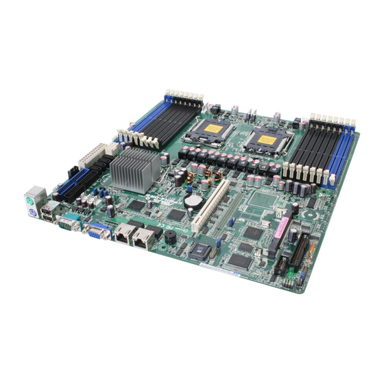
2.2.3 Motherboard layout 33.0cm(13in) REAR_FAN4 ATXPWR1 USB34 KBMS1 PSUSMB1 PRI_IDE1 DDR2 DIMM_B2 (64 bit,240-pin module) KBPWR1 ATX12V1 SEC_IDE1 DDR2 DIMM_A2 (64 bit,240-pin module) USB12 DDR2 DIMM_B1 (64 bit,240-pin module) USBPW12 REAR_FAN3 DDR2 DIMM_A1 (64 bit,240-pin module) REAR_FAN2 REAR_FAN1 LAN1_EN1 LAN2_EN1 nForce Professional 2200 Broadcom... -
Page 25: Layout Contents
Rear panel connectors Page PS/2 mouse port (green) 2-21 PS/2 keyboard port (purple) 2-21 USB 2.0 ports 1 and 2 2-21 Serial (COM 1) port 2-21 VGA port 2-21 LAN 1 (RJ-45) port 2-21 LAN 2 (RJ-45) port 2-21 ASUS KFN4-DRE... - Page 26 Internal connectors Page Floppy disk drive connector (34-1 pin FLOPPY1) 2-22 IDE connectors (40-1 pin PRI_IDE1, SEC_IDE1) 2-23 Serial ATA connectors (7-pin SATA1, SATA2, SATA3, SATA4) 2-24 Backplane SMBus connector (6-1 pin BPSMB1) 2-24 Storage add-in card activity LED connector (4-pin HDLED1) 2-25 USB connectors (10-1 pin USB34) 2-25...
-
Page 27: Central Processing Unit (Cpu)
Contact your retailer immediately if the PnP cap is missing, or if you see any damage to the PnP cap/socket contacts/motherboard components. ASUS shoulders the repair cost only if the damage is shipment/ transit-related. •... - Page 28 Press the load lever with your thumb (A), then move it to the left (B) until it is released from the retention tab. Retention tab PnP cap Load lever This side of the socket box should face you. To prevent damage to the socket pins, do not remove the PnP cap unless you are installing a CPU.
- Page 29 The CPU fits in only one correct orientation. DO NOT force the CPU into the socket to prevent bending the connectors on the socket and damaging the CPU! Close the load plate (A), then push the load lever (B) until it snaps into the retention tab. ASUS KFN4-DRE...
-
Page 30: Installing The Heatsink
2.3.2 Installing the heatsink The AMD Opteron™ 2000 series processors require a specially designed heatsink to ensure optimum thermal condition and performance. Make sure that you use only qualified heatsink assembly. Follow these steps to install the CPU heatsink. Place the heatsink on top of the installed CPU, making sure that the screw holes are matched with the heatsink standoffs. -
Page 31: System Memory
DIMM_B2 DIMM_A2 DIMM_B1 DIMM_A1 DIMM_C1 DIMM_D1 DIMM_C2 DIMM_D2 112 Pins 128 Pins KFN4-DRE 240-pin DDR2 DIMM Sockets For CPU 1 Sockets Channel A DIMM_A1 and DIMM_A2 Channel B DIMM_B1 and DIMM_B2 For CPU 2 Sockets Channel A DIMM_C1 and DIMM_C2... -
Page 32: Memory Configurations
2.4.2 Memory Configurations You may install 256 MB, 512 MB, 1 GB, 2, or 4 GB registered ECC DDR2 DIMMs into the DIMM sockets using the memory configurations in this section. • For dual-channel configuration, the total size of memory module(s) installed per channel must be the same for better performance. -
Page 33: Installing A Dimm
DIMM. Support the DIMM lightly with your fingers when pressing the retaining clips. The DIMM might get damaged when it DDR2 DIMM notch flips out with extra force. Remove the DIMM from the socket. ASUS KFN4-DRE 2-13... -
Page 34: Expansion Slots
Expansion slots In the future, you may need to install expansion cards. The following sub-sections describe the slots and the expansion cards that they support. Make sure to unplug the power cord before adding or removing expansion cards. Failure to do so may cause you physical injury and damage motherboard components. -
Page 35: Interrupt Assignments
* These IRQs are usually available for ISA or PCI devices. 2.5.4 PCI Express x16 slot This motherboard supports PCI Express x16 graphic cards that comply with the PCI Express specifications. The figure shows a graphics card installed on the PCI Express x16 slot. ASUS KFN4-DRE 2-15... -
Page 36: Pci Slots
2.5.5 PCI slots The PCI slots support cards such as a LAN card, SCSI card, USB card, and other cards that comply with PCI specifications. The figure shows a LAN card installed on a PCI slot. 2.5.6 HTX slot The HTX slot supports HTX InfiniBand card that complys with HTX interface specifications. -
Page 37: Jumpers
6. Hold down the <Del> key during the boot process and enter BIOS setup to re-enter data. Except when clearing the RTC RAM, never remove the cap on CLRTC jumper default position. Removing the cap will cause system boot failure! CLRTC1 Normal Clear CMOS (Default) KFN4-DRE Clear RTC RAM ASUS KFN4-DRE 2-17... - Page 38 +5VSB lead, and a corresponding setting in the BIOS. KBPWR1 +5VSB (Default) KFN4-DRE Keyboard Power Setting Gigabit LAN1 controller setting (3-pin LAN1_EN1) This jumper allows you to enable or disable the onboard Broadcom ® BCM5721 Gigabit LAN1 controller. Set to pins 1-2 to activate the Gigabit LAN feature.
- Page 39 (CPU stopped, DRAM refreshed, system running in low power mode) using the connected USB devices. Set to +5VSB to wake up from S4 and S5 sleep modes (no power to CPU, DRAM). USBPW23 USBPW12 +5VSB (Default) KFN4-DRE USB device Wake up ASUS KFN4-DRE 2-19...
- Page 40 RECOVERY1 Normal BIOS Recovery (Default) KFN4-DRE BIOS Recovery Setting VGA Graphics controller setting (3-pin VGA_EN1) This jumper allows you to enable or disable the onboard ATI ES1000 video graphics controller. Set to pins 1-2 to enable the video graphics controller.
-
Page 41: Connectors
LAN port LED indications. LAN port LED indications ACT/LINK SPEED ACT/LINK LED SPEED LED Status Description Status Description No link 10 Mbps connection GREEN Linked ORANGE 100 Mbps connection LAN port BLINKING Data activity GREEN 1 Gbps connection ASUS KFN4-DRE 2-21... -
Page 42: Internal Connectors
Insert one end of the cable to this connector, then connect the other end to the signal connector at the back of the floppy disk drive. FLOPPY1 PIN 1 NOTE: Orient the red markings on the floppy ribbon cable to PIN 1. KFN4-DRE Floppy Disk Drive Connector 2-22 Chapter 2: Hardware information... -
Page 43: Ide Connectors (40-1 Pin Pri_Ide1, Sec_Ide)
If any device jumper is set as “Cable-Select,” make sure all other device jumpers have the same setting. PRI_IDE1 PIN1 SEC_IDE1 PIN1 NOTE: Orient the red markings (usually zigzag) on the ID ribbon cable to PIN 1. KFN4-DRE IDE Connectors ASUS KFN4-DRE 2-23... -
Page 44: Serial Ata Connectors (7-Pin Sata1, Sata2, Sata3, Sata)
RSATA_TXN1 RSATA_TXP2 RSATA_TXP4 RSATA_TXP3 RSATA_TXP1 KFN4-DRE SATA Connectors Important notes on Serial ATA The actual data transfer rate depends on the speed of Serial ATA hard disks installed. Backplane SMBus connector (6-1 pin BPSMB1) This connector allows you to connect SMBus (System Management Bus) devices. - Page 45 SCSI or SATA add-on card causes the front panel LED to light up. HDLED1 KFN4-DRE Hard Disk Activity LED Connector USB connector (10-1 pin USB34) This connector is for USB 2.0 ports. This connector complies with the USB 2.0 specification that supports up to 480 Mbps connection speed.
- Page 46 Do not forget to connect the fan cables to the fan connectors. Lack of sufficient air flow inside the system may damage the motherboard components. These are not jumpers! DO NOT place jumper caps on the fan connectors! • All fan features the ASUS Smart Fan technology. FRNT_FAN5 FRNT_FAN6 REAR_FAN3 FRNT_FAN4...
-
Page 47: Serial Port Connector (10-1 Pin Com)
COM2 PIN 1 KFN4-DRE COM Port Connector ATX power connectors (24-pin ATXPWR1, 8-pin ATX12V1) These connectors are for an ATX power supply plugs. The power supply plugs are designed to fit these connectors in only one orientation. -
Page 48: Power Supply Smbus Connector (5-Pin Psusmb)
SMBus host and/or other SMBus devices using the SMBus interface. PSUSMB1 KFN4-DRE Power Supply SMBus Connector 11. Parallel port connector (26-1 pin LPT1) This connector is for a parallel port. Connect the parallel port module cable to this connector, then install the module to a slot opening at the back of the system chassis. -
Page 49: Bmc Connector (200-Pin Bmcsocket)
12. BMC connector (200-pin BMCSOCKET1) This connectors is for the ASUS server management card. BMCSOCKET1 KFN4-DRE BMCSOCKET Connector ASUS KFN4-DRE 2-29... -
Page 50: System Panel Auxiliary Connector (20-2 Pin Aux_Panel)
13. System panel auxiliary connector (20-2 pin AUX_PANEL1) This connector supports several server system functions. AUX_PANEL1 KFN4-DRE Auxiliary Panel Connector • Chassis Intrusion connector (3-pin CASEOPEN) This lead is for a chassis with an intrusion detection feature. This requires an external detection mechanism such as a chassis intrusion sensor or microswitch. -
Page 51: System Panel Connector (20-1 Pin Panel)
14. System panel connector (20-1 pin PANEL1) This connector supports several chassis-mounted functions. PANEL1 KFN4-DRE System Panel Connector The system panel connector is color-coded for easy connection. Refer to the connector description below for details. • System power LED (Green 3-pin POWERLED) This 3-pin connector is for the system power LED. - Page 52 2-32 Chapter 2: Hardware information...
-
Page 53: Chapter 3: Powering Up
This chapter describes the power up sequence, the POST messages, and ways of shutting down the system. Powering up... -
Page 54: Chapter Summary
Chapter summary Starting up for the first time ..........3-1 Powering off the computer ........... 3-2 ASUS KFN4-DRE... -
Page 55: Starting Up For The First Time
Check the jumper settings and connections or call your retailer for assistance. At power on, hold down the <Del> key to enter the BIOS Setup. Follow the instructions in Chapter 4. ASUS KFN4-DRE... -
Page 56: Powering Off The Computer
Powering off the computer 3.2.1 Using the OS shut down function If you are using Windows 2000/2003 Server: ® Click the Start button then click Shut Down... Select Shut Down from the What do you want the computer to do? list box. -
Page 57: Chapter 4: Bios Setup
This chapter tells how to change the system settings through the BIOS Setup menus. Detailed descriptions of the BIOS parameters are also provided. BIOS setup... - Page 58 Chapter summary Managing and updating your BIOS ........4-1 BIOS setup program ............4-10 Main menu ................4-13 Advanced menu ..............4-19 Server menu................ 4-29 Security menu ..............4-31 Boot menu ................4-34 Exit menu ................4-37 ASUS KFN4-DRE...
-
Page 59: Managing And Updating Your Bios
The following utilities allow you to manage and update the motherboard Basic Input/Output System (BIOS) setup. ASUS AFUDOS (Updates the BIOS in DOS mode using a bootable floppy disk.) ASUS CrashFree BIOS 2 (Updates the BIOS using a bootable floppy disk or the motherboard support CD when the BIOS file fails or gets corrupted.) -
Page 60: Afudos Utility
A:\>afudos /oOLDBIOS1.rom Main filename Extension name Press <Enter>. The utility copies the current BIOS file to the floppy disk. A:\>afudos /oOLDBIOS1.rom AMI Firmware Update Utility - Version 1.19(ASUS V2.07(03.11.24BB)) Copyright (C) 2002 American Megatrends, Inc. All rights reserved. Reading flash ..done Write to file..ok A:\>... -
Page 61: Updating The Bios File
Updating the BIOS file To update the BIOS file using the AFUDOS utility: Visit the ASUS website (www.asus.com) and download the latest BIOS file for the motherboard. Save the BIOS file to a bootable floppy disk. Write the BIOS filename on a piece of paper. You need to type the exact BIOS filename at the DOS prompt. - Page 62 The utility returns to the DOS prompt after the BIOS update process is completed. Reboot the system from the hard disk drive. A:\>afudos /iKFN4DRE.ROM /pbnc AMI Firmware Update Utility - Version 1.19(ASUS V2.07(03.11.24BB)) Copyright (C) 2002 American Megatrends, Inc. All rights reserved. WARNING!! Do not turn off power during flash BIOS Reading file ..done...
-
Page 63: Asus Crashfree Bios 2 Utility
4.1.3 ASUS CrashFree BIOS 2 utility The ASUS CrashFree BIOS 2 is an auto recovery tool that allows you to restore the BIOS file when it fails or gets corrupted during the updating process. You can update a corrupted BIOS file using the motherboard support CD or the floppy disk that contains the updated BIOS file. -
Page 64: Recovering The Bios From The Support Cd
Restart the system after the utility completes the updating process. The recovered BIOS may not be the latest BIOS version for this motherboard. Visit the ASUS website (www.asus.com) to download the latest BIOS file. Chapter 4: BIOS setup... -
Page 65: Asus Update Utility
4.1.4 ASUS Update utility The ASUS Update is a utility that allows you to manage, save, and update the motherboard BIOS in Windows environment. The ASUS Update utility ® allows you to: • Save the current BIOS file • Download the latest BIOS file from the Internet •... -
Page 66: Updating The Bios Through The Internet
To update the BIOS through the Internet: Launch the ASUS Update utility from the Windows desktop by clicking ® Start > Programs > ASUS > ASUSUpdate > ASUSUpdate. The ASUS Update main window appears. Select Update BIOS from Select the ASUS FTP site... -
Page 67: Updating The Bios Through A Bios File
To update the BIOS through a BIOS file: Launch the ASUS Update utility from the Windows desktop by ® clicking Start > Programs > ASUS > ASUSUpdate > ASUSUpdate. The ASUS Update main window appears. Select Update BIOS from a file option from the drop-down menu, then click Next. -
Page 68: Bios Setup Program
The BIOS setup screens shown in this section are for reference purposes only, and may not exactly match what you see on your screen. • Visit the ASUS website (www.asus.com) to download the latest BIOS file for this motherboard. 4-10... -
Page 69: Bios Menu Screen
At the bottom right corner of a menu screen are the navigation keys for that particular menu. Use the navigation keys to select items in the menu and change the settings. Some of the navigation keys differ from one screen to another. ASUS KFN4-DRE 4-11... -
Page 70: Menu Items
System Time [11:10:19] Use [ENTER], [TAB] System Date [Thu 03/27/2003] or [SHIFT-TAB] to Legacy Diskette A [1.44M, 3.5 in] select a field. Language [English] For example, selecting Main shows the Use [+] or [-] to Primary IDE Master :[ST320413A] configure system time. Primary IDE Slave :[ASUS CD-S340] Secondary IDE Master :[Not Detected] Main menu items. Secondary IDE Slave :[Not Detected] Third IDE Master :[Not Detected] Fourth IDE Master :[Not Detected] Select Screen IDE Configuration Select Item Change Field System Information The other items (Advanced, Power, Boot,... -
Page 71: Main Menu
Allows you to set the system time. 4.3.3 Floppy A [1.44M, 3.5 in.] Sets the type of floppy drive installed. Configuration options: [Disabled] [360K, 5.25 in.] [1.2M , 5.25 in.] [720K , 3.5 in.] [1.44M, 3.5 in.] [2.88M, 3.5 in.] ASUS KFN4-DRE 4-13... -
Page 72: Ide Configuration
4.3.4 IDE Configuration The items in this menu allow you to set or change the configurations for the IDE devices installed in the system. Select an item then press <Enter> if you wish to configure the item. BIOS SETUP UTILITY Main IDE Configuration OnBoard PCI IDE Controller... - Page 73 Enables or disables the NVIDIA RAID option ROM. ® Configuration options: [Disabled] [Enabled] The following items appear when the RAID Option ROM is Enabled. Tertiary/Fourth/Fifth/Sixth Master as RAID [Disabled] Sets the tertiary/fourth/fifth/sixth master interface as RAID. Configuration options: [Disabled] [Enabled] ASUS KFN4-DRE 4-15...
-
Page 74: Primary, Secondary, Tertiary, Fourth, Fifth, And Sixth Ide Master/Slave
4.3.5 Primary, Secondary, Tertiary, Fourth, Fifth, and Sixth IDE Master/Slave The BIOS automatically detects the connected IDE devices. There is a separate sub-menu for each IDE device. Select a device item, then press <Enter> to display the IDE device information. BIOS SETUP UTILITY Main Primary IDE Master... -
Page 75: System Information
System Information This menu gives you an overview of the general system specifications. The BIOS automatically detects the items in this menu. BIOS SETUP UTILITY Main System Information Model Name ASUS KFN4-DRE Model ID 8031A0 ASUS BIOS Version 1001 Date 06/22/2006 Processor →←... - Page 76 Processor Displays the installed processor information. BIOS SETUP UTILITY Main Processor Information ***CPU1: Brand AMD Dual-Core AMD Opteron(tm) Processor 2212 ID/uCode 040F12h/None Speed 2.00GHz Ratio Actual 10 Max 10 Cache L1/256KB L2/2048KB Revision →← Select Screen ↑↓ Select Item Change Field Select Field General Help F10 Save and Exit ESC Exit V00.00 (C)Copyright 1985-2004, American Megatrends, Inc.
-
Page 77: Advanced Menu
[1.4] MTRR Mapping [Continuous] PowerNow [Enabled] →← Select Screen ↑↓ Select Item Change Field Select Field General Help F10 Save and Exit ESC Exit V00.00 (C)Copyright 1985-2004, American Megatrends, Inc. MPS Table Version [1.4] Sets the Multi-Processor System (MPS) table version. Configuration options: [1.1] [1.4] ASUS KFN4-DRE 4-19... -
Page 78: Chipset Configuration
MTRR Mapping [Continuous] Determines the method used for programming processor MTRRs when using more than 4GB of system memory. Configuration options: [Continuous] [Discrete] PowerNow [Enabled] Enables or disables the generation of ACPI_PPC/_PSS/_PCT objects. Configuration options: [Enabled] [Disabled] 4.4.2 Chipset Configuration The Chipset configuration menu allows you to change advanced chipset settings. -
Page 79: Memory Configuration
The following item appears when the Memclock Mode is set to Limit or Manual. Memclock Value [400 MHz] Sets the memory clock mode limit. Configuration options: [400 MHz] [533 MHz] [667 MHz] Memoryy Hole Remapping [Enabled] Enables or disables the memory remapping around memory hole. Configuration options: [Disabled] [Enabled] ASUS KFN4-DRE 4-21... -
Page 80: Ecc Configuration
ECC Configuration ECC Configuration DRAM ECC allows hardware to report DRAM ECC Enable [Enabled] and correct memory Chipkill ECC Mode [Disabled] errors automatically DRAM ADDRESS PARITY Enable [Disabled] maintaining system integrity. DRAM ECC Enable [Disabled] Allows you to enable or disable the DRAM ECC. Configuration options: [Disabled] [Enabled] Chipkill ECC Mode [Disabled] Enables or disables the Chipkill ECC mode. -
Page 81: Southbridge Configuration
SouthBridge Configuration CPU Spread Spectrum [Disabled] →← Select Screen ↑↓ Select Item Change Field Select Field General Help F10 Save and Exit ESC Exit V00.00 (C)Copyright 1985-2004, American Megatrends, Inc. CPU Spread Spectrum [Disabled] Sets or disables the processor clock spread spectrum. Configuration options: [Disabled] [Center Spread] ASUS KFN4-DRE 4-23... -
Page 82: Pci Pnp
4.4.3 PCI PnP The PCI PnP menu items allow you to change the advanced settings for PCI/PnP devices. The menu includes setting IRQ and DMA channel resources for either PCI/PnP or legacy ISA devices, and setting the memory size block for legacy ISA devices. -
Page 83: Usb Configuration
Allows you to set the USB 2.0 controller mode to HiSpeed (480 Mbps) or FullSpeed (12 Mbps). Configuration options: [HiSpeed ] [FullSpeed ] BIOS EHCI Hand-Off [Enabled] Enables or disables the BIOS EHCI hand-off support. Configuration options: [Disabled] [Enabled] ASUS KFN4-DRE 4-25... -
Page 84: Peripheral Devices Configuration
4.4.5 Peripheral Devices Configuration BIOS SETUP UTILITY Advanced Peripheral Devices Configuration OnBoard Floppy Controller [Enabled] Serial Port1 Address [3F8/IRQ4] Serial Port2 Address [2F8/IRQ3] Serial Port2 Address [Normal] Parallel Port Address [Disabled] →← Select Screen ↑↓ Select Item Change Field Select Field General Help F10 Save and Exit ESC Exit V00.00 (C)Copyright 1985-2004, American Megatrends, Inc. OnBoard Floppy Controller [Enabled] Enables or disables the onboard floppy controller. -
Page 85: Acpi Configuration
Enables or disables the headless operation mode in ACPI. Configuration options: [Disabled] [Enabled] ACPI EMS Support [Disabled] Enables or disables the ACPI EMS support. Configuration options: [Disabled] [Enabled] ACPI MCFG Support [Enabled] Enables or disables the ACPI MCFG support. Configuration options: [Disabled] [Enabled] ASUS KFN4-DRE 4-27... -
Page 86: Apm Configuration
4.4.7 APM Configuration This sub-menu allows you to change Advanced Power Management (APM) features. Select an item then press <Enter> to display the configuration options. BIOS SETUP UTILITY Advanced APM Configuration Restore On AC Power Loss [Power Off] Resume by PS/2 Keyboard [Enabled] Resume by PS/2 Mouse [Disabled] Resume by Ring [Disabled] Resume by PME# [Enabled] Resume by RTC [Disabled] →←... -
Page 87: Hardware Monitor
N/A. Smart Fan Control [Smart Fan II] Allows you to enable or disable the ASUS Smart Fan feature that smartly adjusts the fan speeds for more efficient system operation. Configuration options: [Disabled] [Smart Fan] [Smart Fan II]... -
Page 88: Trusted Computing
The CPU1 Temperature, CPU2 Temperature, and Front1 Temperature items appear when you enable the Smart Fan Control feature. CPU1/CPU2 Temperature [XXX] Front1 Temperature [XXX] Allows you to set the CPU and system threshold temperature before the Smart Fan Control is disabled. Use the arrow down key to scroll down the menu. -
Page 89: 4.4.10 Asuslog Configuration
Configuration options: [Disabled] [Enabled] ASUS Event Log Viewer The sub-menu allows you to view all events in the ASUS Event Log. It will take a max. of 15 seconds to read all ASUS Event Log records. Total Number of Entries:... -
Page 90: Server Menu
Server menu BIOS SETUP UTILITY Main Advanced Server Security Boot Exit Configure Remote Remote Access Configuration Access. →← Select Screen ↑↓ Select Item Change Field Select Field General Help F10 Save and Exit ESC Exit V00.00 (C)Copyright 1985-2004, American Megatrends, Inc. Remote Access Configuration The items in this menu allows you to configure the Remote Access features. - Page 91 VT-UTF8 Combo Key Support [Disabled] Enables or disables the VT-UTF8 combo key support for ANSI or VT100 terminals. Configuration options: [Disabled] [Enabled] Media Type [Serial] Allows you to select the media for console redirection. Configuration options: [Serial] [LAN] [Serial + LAN] ASUS KFN4-DRE 4-33...
-
Page 92: Security Menu
Security menu The Security menu items allow you to change the system security settings. Select an item then press <Enter> to display the configuration options. BIOS SETUP UTILITY Main Advanced Server Security Boot Exit Supervisor Password : Not Installed Install or Change the User Password : Not Installed password. -
Page 93: Change User Password
<Enter>. Confirm the password when prompted. The message “Password Installed” appears after you set your password successfully. To change the user password, follow the same steps as in setting a user password. ASUS K8N-DRE 4-35... - Page 94 Password Check [Setup] When set to [Setup], BIOS checks for user password when accessing the Setup utility. When set to [Always], BIOS checks for user password both when accessing Setup and booting the system. Configuration options: [Setup] [Always] 4-36 Chapter 4: BIOS setup...
-
Page 95: Boot Menu
These items specify the boot device priority sequence from the available devices. The number of device items that appears on the screen depends on the number of devices installed in the system. Configuration options: [xxxxx Drive] [Disabled] ASUS K8N-DRE 4-37... -
Page 96: Boot Settings Configuration
Allows you to enable or disable the full screen logo display feature. Configuration options: [Disabled] [Enabled] Set this item to [Enabled] to use the ASUS MyLogo2™ feature. Bootup Num-Lock [On] Allows you to select the power-on state for the NumLock. -
Page 97: Exit Menu
Select this option only if you do not want to save the changes that you made to the Setup program. If you made changes to fields other than System Date, System Time, and Password, the BIOS asks for a confirmation before exiting. ASUS K8N-DRE 4-39... -
Page 98: Discard Changes
Discard Changes Allows you to discard the selections you made and restore the previously saved values. After selecting this option, a confirmation appears. Select Ok to discard any changes and load the previously saved values. Load Setup Defaults Allows you to load the default values for each of the parameters on the Setup menus. - Page 99 This chapter provides instructions for setting up, creating, and configuring RAID sets using the available utilities. R AID configuration...
- Page 100 Chapter summary Setting up RAID ..............5-1 NVIDIA RAID configurations..........5-3 ® ASUS KFN4-DRE...
-
Page 101: Setting Up Raid
If you want to boot the system from a hard disk drive included in a created RAID set, copy first the RAID driver from the support CD to a floppy disk before you install an operating system to the selected hard disk drive. Refer to Chapter 6 for details. ASUS KFN4-DRE... -
Page 102: Installing Hard Disk Drives
5.1.2 Installing hard disk drives The motherboard supports Serial ATA (both models) and SCSI hard disk drives (SCSI model only) for RAID set configuration. For optimal performance, install identical drives of the same model and capacity when creating a disk array. To install the SATA hard disks for RAID configuration: Install the SATA hard disks into the drive bays following the instructions in the system user guide. -
Page 103: Nvidia ® Raid Configurations
Refer to Chapter 4 for details on entering and navigating through the BIOS Setup. • The RAID BIOS setup screens shown in this section are for reference only, and may not exactly match the items on your screen. ASUS KFN4-DRE... -
Page 104: Entering The Nvidia ® Raid Utility
5.2.2 Entering the NVIDIA RAID Utility ® To enter the NVIDIA RAID Utility: ® Restart the computer. During POST, press <F10> to display the utility main menu. Media Shield Utility - Define a New Array - RAID Mode: Mirroring Striping Block: Optimal Free Disks Array Disks Disk Model Name Disk Model Name 1.0.M... -
Page 105: Creating A Raid Volume
Highlight the hard disk drives that you want to add in the RAID set, then press the right arrow key to select. The selected hard disk drives appear in the Array Disks section. Repeat the process until all desired hard disk drives are added. ASUS KFN4-DRE... - Page 106 Media Shield Utility - Define a New Array - RAID Mode: Mirroring Striping Block: Optimal Free Disks Array Disks Disk Model Name Disk Model Name 1.0.M XXXXXXXXXXXXXXXXXX [→] Add 1.1.M XXXXXXXXXXXXXXXXXX [←] Del [F6] Back [F7] Finish [TAB] Navigate [↑↓] Select [ENTER] Popup Press <F7> to create RAID set. A pop-up Clear disk data? window appears. [Y] YES [N] Cancel Press <Y>...
-
Page 107: Rebuilding A Raid Set
Striping Width: 1 Striping Block: 64K Adapt Channel M/S Index Disk Model Name Capacity Master XXXXXXXXXXXXXXXXX XXX.XXGB Master XXXXXXXXXXXXXXXXX XXX.XXGB [↑↓] Select [F6] Back [F7] Finish Press <Enter> to start rebuilding the array, Rebuild array? or <Esc> to cancel. The Array List screen [Enter] OK [Esc] Cancel displays the RAID set after rebuilding. ASUS KFN4-DRE... -
Page 108: Deleting A Raid Array
5.2.5 Deleting a RAID array To delete a RAID array: From the Array List, use the up or down arrow keys to select the RAID set you want to delete, then press <Enter>. The RAID set details appear. Media Shield Utility - Array List - Boot Status... -
Page 109: Clearing The Disk Data
Striping Width: 1 Striping Block: 64K Adapt Channel M/S Index Disk Model Name Capacity Master XXXXXXXXXXXXXXXXX XXX.XXGB Master XXXXXXXXXXXXXXXXX XXX.XXGB [R] Rebuild [D] Delete [C] Clear Disk [ENTER] Return Press <Y> to clear the disk data, or press Clear disk data? <N> to cancel.Press <C> to clear disk. The [Y] Yes [N] Cancel following confirmation message appears. ASUS KFN4-DRE... -
Page 110: Installing The Raid Controller Driver In
5.2.7 Installing the RAID controller driver in Windows XP OS ® During Windows XP OS installation ® To install the RAID controller driver when installing Windows XP OS: ® Boot the computer using the Windows XP installation CD. The ® Windows XP Setup starts. - Page 111 Insert the RAID driver disk you created earlier to the floppy disk drive, press <S>, then press <Enter>. Select NVDIA RAID CLASS DRIVER (required), then press <Enter>. NVIDIA RAID CLASS DRIVER (required) NVIDIA nForce Storage Controller (required) Press <S> again at the Specigy Devices screen, then press <Enter>. ASUS KFN4-DRE 5-11...
- Page 112 Select NVDIA RAID CLASS DRIVER (required), then press <Enter>. The following window appears listing both derivers. Setup will load support for the following mass storage device: NVIDIA RAID CLASS DRIVER NVIDIA NForce Storage Controller * To specify additional SCSI adapters, CD-ROM drives, or special disk controllers for use with Windows, including those for which you have a device support disk from a mass storage device manufacturer, press S.
-
Page 113: Chapter 6: Driver Installation
This chapter provides instructions for installing the necessary drivers for different system components. Driver installation... - Page 114 Chapter summary RAID driver installation ............6-1 LAN driver installation ............6-3 Support CD information ............6-4 ASUS KFN4-DRE...
-
Page 115: Raid Driver Installation
D) Create NVIDIAR nForce SATA RAID for Windows 2003 64 bit Driver Disk Please choose A TO D: Place a blank, high-density floppy disk to the floppy disk drive. When you insert a floppy disk with data, the utility erases all the data before copying the RAID drivers. ASUS KFN4-DRE... - Page 116 Type the letter of the option you like to select, then press <Enter>. For example, if you want to create an NVIDIA nForce(TM) SATA RAID driver disk for a 64-bit Windows 2003 system, press <D>, then press <Enter>. The RAID drivers are copied to the floppy disk. After creating a RAID driver disk, eject the floppy disk, then write-protect it to prevent computer virus infection.
-
Page 117: Lan Driver Installation
CD to locate the file ASSETUP.EXE from the BIN folder. Double-click the ASSETUP.EXE to run the CD. Click the Broadcom 5721 driver option to begin installation. Click Next when the InstallShield Wizard window appears. Follow screen instructions to continue installation. ASUS KFN4-DRE... -
Page 118: Support Cd Information
The contents of the support CD are subject to change at any time without notice. Visit the ASUS website (www.asus.com) for updates. 6.4.1 Running the support CD Place the support CD to the optical drive. -
Page 119: Drivers Menu
Installs the Broadcom 5751 NetXtreme Gigabit Ethernet driver. See page 6-3 for details. Broadcom 5721 NetXtreme Software Utility Installs the Broadcom NetXtreme software application. Refer to the application help file for details. Infineon Security Platform Software Installs the Infineon Security Platform software. ASUS KFN4-DRE... -
Page 120: Management Software
The Management Software menu shows the available server management software applications. Install ASUS Network Utility Installs the ASUS Network Utility. Refer to the application help file for details. ASWM Installs the ASUS System Web-base Management utility. Refer to the application help file for details. -
Page 121: Utilities
Reader V7.0 is for opening, viewing, and printing ® documents in Portable Document Format (PDF). ASUS Screen Saver Bring life to your idle screen by installing the ASUS screen saver. ASUS Update The ASUS Update utility that allows you to update the motherboard BIOS in Windows environment. -
Page 122: Contact Information
6.4.5 Contact information Click the Contact tab to display the ASUS contact information. You can also find this information on the inside front cover of this user guide. Chapter 6: Driver installation...
Need help?
Do you have a question about the KFN4-DRE and is the answer not in the manual?
Questions and answers