Table of Contents
Advertisement
Advertisement
Table of Contents

Subscribe to Our Youtube Channel
Related Manuals for Chauvet Vue 2.1


Summary of Contents for Chauvet Vue 2.1
-
Page 1: User Manual
Snapshot ™ Ok on Dimmer Outdoor OK Sound Activated DMX512 Master/Slave Autoswitching Transformer Replaceable Fuse User Serviceable Duty Cycle USER MANUAL Chauvet, 3000 N 29 Ct, Hollywood, FL 33020 U.S.A. (800) 762-1084 – (954) 929-1115 FAX (954) 929-5560 www.chauvetlighting.com... -
Page 2: Table Of Contents
ABLE OF ONTENTS 1. Before You Begin ..........................3 What is included ............................3 Unpacking Instructions ..........................3 AC Power ..............................3 Contact Us ..............................3 Safety Instructions ............................ 4 2. Introduction ............................5 Features ..............................5 DMX Channel Summary ..........................5 Product Overview............................ -
Page 3: Before You Begin
(variable resistor) or dimmer circuit, even if the rheostat or dimmer channel is used solely for a 0% to 100% switch. Contact Us Wor l d Wi de General Information Chauvet Lighting 3000 North 29 Court Hollywood, FL 33020 voice: 954.929.1115... -
Page 4: Safety Instructions
Caution! There are no user serviceable parts inside the unit. Do not open the housing or attempt any repairs yourself. In the unlikely event your unit may require service, please contact CHAUVET at: 954-929-1115. Vue™ 2.1 User Manual 2008-08-21/17:09... -
Page 5: Introduction
2. I NTRODUCTION Features 7-channel DMX-512 LED rotating moon flower Blackout/static/strobe Individual control of 4 separate sections Speed and direction control of motor Built-in automated programs via master/slave or DMX Built-in sound activated programs via master/slave or DMX ADDITIONAL FEATURES Contains red, green, blue, white and amber LEDs Adjustable hanging bracket with slide rail Additional power output: max 26 units @ 120V... -
Page 6: Product Overview
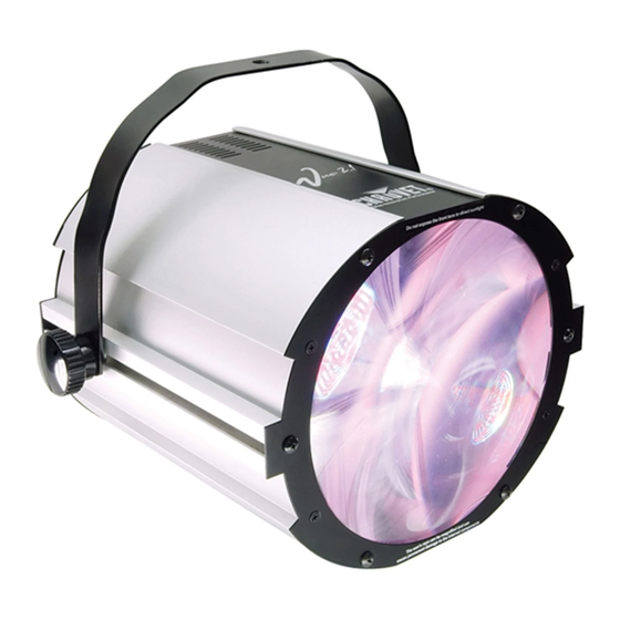
Product Overview Hanging Bracket Front Lens Tilt Adjustment Knob Sound Sensitivity Digital Knob Display Microphone Power DMX Input Output Connector Connector AC Power Input & Fuse Output Connector Vue™ 2.1 User Manual 2008-08-21/17:09... -
Page 7: Setup
Maximum recommended number of fixtures on a serial data link: 32 fixtures Data Cabling To link fixtures together you must obtain data cables. You can purchase CHAUVET-certified DMX cables directly from a dealer/distributor or construct your own cable. If you choose to create your own cable please use data-grade cables that can carry a high quality signal and are less prone to electromagnetic interference. -
Page 8: Cable Connectors
If you use a controller with a 5 pin DMX output connector, you will need to use a 5 pin to 3 pin adapter. Note! CHAUVET Model No: DMX5M, or DMX5F. The chart below details a proper cable conversion: IN TO... -
Page 9: Stand-Alone & Master/Slave Fixture Linking
Stand-Alone & Master/Slave Fixture Linking 1. Connect the (male) 3 pin connector side of the DMX cable to the output (female) 3 pin connector of the first fixture. 2. Connect the end of the cable coming from the first fixture which will have a (female) 3 pin connector to the input connector of the next fixture consisting of a (male) 3 pin connector. -
Page 10: Operating Instructions
4. O PERATING NSTRUCTIONS Operation Stand-Alone Mode (Sound-Active, Auto Mode, Strobe Mode, All On): This mode allows a single unit to run to the beat of the music, or the unit will auto change in Auto Mode. This fixture will automatically begin operating in standalone mode when there is no DMX signal present from a DMX controller. -
Page 11: Dmx Channel Values
DMX Channel Values HANNEL ALUE UNCTION Control/Operating Mode 000 011 Individual cluster control 012 017 Auto 1 018 023 Auto 2 024 029 Auto 3 030 035 Auto 4 036 041 Auto 5 042 047 Auto 6 048 ... -
Page 12: Menu Map
Display Options Menu Map UNCTION ELECTION NSTRUCTION SET.d d:000-d:512 Sets the DMX starting address SET.S S:100-s:100 Sets the speed of the current program SET.f F:000-f:100 Sets the flash rate of the current program SET.A A:000-a:024 Selects the current program in standalone This is displaying that the fixture is SUND operating in sound activation mode... -
Page 13: Setting The Starting Address
SETTING THE STARTING ADDRESS This DMX mode enables the use of a universal DMX controller device. Each fixture requires a "start address" from 1 to 512. A fixture requiring one or more channels for control begins to read the data on the channel indicated by the start address. -
Page 14: Dmx Quick Reference Chart
DMX Q UI CK REF ERENCE CH ART DMX Address Quick Reference Chart Dip Switch Position DMX DIP #9 0 0 0 SWITCH SET 0=OFF #8 0 0 0 1=ON #7 0 0 1 X=OFF or ON #6 0 1 0 #1 #2 #3 #4 #5 0 0 0 0 0 32 64 96 128 160 192 224 256 288 320 352 384 416 448 480... -
Page 15: General Troubleshooting
If you still have a problem after trying the above solutions, please contact CHAUVET Technical Support at the location on the next page. Vue™ 2.1 User Manual... -
Page 16: Technical Support
XLR male to female connectors. The shield connection is pin 1, while pin 2 is Data Negative (S-) and pin 3 is Data positive (S+). CHAUVET carries 3-pin XLR DMX compliant cables, DMX-10 (33’), DMX-4.5 (15’) and DMX-1.5 (5’) General Maintenance To maintain optimum performance and minimize wear fixtures should be cleaned frequently. -
Page 17: Returns Procedure
Package must be clearly labeled with a Return Merchandise Authorization Number (RMA #). Products returned without an RMA # will be refused. Call CHAUVET and request RMA # prior to shipping the fixture. Be prepared to provide the model number, serial number and a brief description of the cause for the return. -
Page 18: Blow-Out Diagram
Blow-out Diagram Description Part Number P170-VUE21PCB 1 Master PCB P172-VUE21DPY 2 Display PCB P200-21LED 3 LED PCB P110-VUE21 4 Stepper motor P140-VUE21ELT 5 Electronic Transformer P111-21BRKT 6 Bracket knob P150-VUE21LN 7 Vue 2.1 front lens Vue™ 2.1 User Manual 2008-08-21/17:09... -
Page 19: Technical Specifications
Master PCB........................P170-VUE21PCB Master IC..........................P177-VUE21IC Display PCB ........................P172-VUE21DPY LED PCB ..........................P200-21LED Stepper motor .........................P110-VUE21 Electronic Transformer ....................P140-VUE21ELT Bracket knob ........................P111-21BRKT Vue 2.1 front lens....................... P150-VUE21LN WARRANTY INFORMATION Warranty........................2-year limited warranty Vue™ 2.1 User Manual 2008-08-21/17:09...
Need help?
Do you have a question about the Vue 2.1 and is the answer not in the manual?
Questions and answers