Table of Contents
Advertisement
Advertisement
Table of Contents

Related Manuals for Antec P100


Summary of Contents for Antec P100
- Page 1 User P100 Manual...
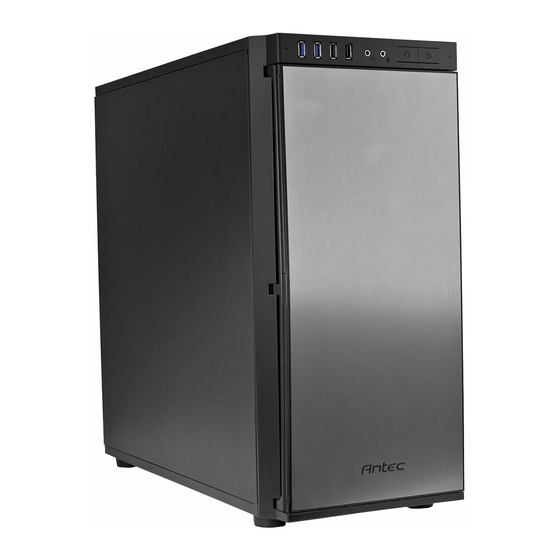
- Page 2 Performance One series design and Quiet Computing™ technologies that minimize system noise. In addition to 7 expansion slots, the P100 also supports 2 tool-less 5.25” drives and 7 tool-less 3.5”/ 2.5” drives. With a great price to feature ratio the P100 is the only economical case that delivers first class silence performance.
-
Page 3: Table Of Contents
Table of Contents Section 1: Introduction Getting to Know Your Chassis ................5 Chassis Specifications..................6 Included Screws ....................6 Before You Begin ....................7 Section 2: Hardware Installation Setting Up ......................9 Motherboard Installation................... 9 Installing KUHLER H O Liquid Coolers ..............11 Power Supply Installation .................. -
Page 4: Section 1: Introduction
Section 1 Introduction P100 User Manual... -
Page 5: Getting To Know Your Chassis
Getting to Know Your Chassis 1. 2 x 5.25” tool-less drive bays 2. 7 x 3.5” / 2.5” drive trays 3. 2 x 120 /140 mm top exhaust fans (optional) 4. 1 x 120 mm rear exhaust fan 5. 2 x 120 /140 mm front intake fans (optional) 6. -
Page 6: Chassis Specifications
Chassis Specifications Chassis Type Mid-Tower Chassis Color Black with aluminum door Dimensions 18.9” (H) x 8.6” (W) x 20.4” (D) 484 mm (H) x 220 mm (W) x 523 mm (D) Weight 16.1 lbs / 7.3 kg Cooling Fan mounts: - 1 x 120mm front intake fan mount - 1 x 120mm rear exhaust fan mount - 1 x 120/ 140 mm front intake fan mounts(optional) -
Page 7: Before You Begin
Before You Begin In order to ensure that your building experience with the P100 will be a positive one, please take note of the following: While working inside your P100, keep your chassis on a flat, stable surface. Make sure your build environment is clean, well-lit, and free of dust. -
Page 8: Section 2: Hardware Installation
Section 2 Hardware Installation P100 User Manual... -
Page 9: Setting Up
Setting Up Put the case upright on a flat, stable surface so that the rear panel (power supply and expansion slots) is facing you. To remove the left and right side panels, remove these thumbscrews first. Note: Place the panel thumbscrews aside carefully and remember where they are. - Page 10 The P100 comes with six preinstalled motherboard standoffs. These are positioned for Standard ATX motherboards but can be relocated to accommodate other form factors. 1. Align the motherboard with the standoff holes on the motherboard tray and remember or mark which holes are lined up 2.
-
Page 11: Installing Kuhler H O Liquid Coolers
Intel® LGA 1155 / 1156 / 1366 / 2011* AMD® AM2 / AM3 / AM2+ / AM3+ / FM1 *Your unit may not contain the LGA 2011 mounting bracket. To acquire this, please contact Antec customer support (information listed at end of manual). -
Page 12: Power Supply Installation
(KUHLER H O 620) or http://www.antec.com/Believe_it/product.php?id=NzA0MzcwJjE3 (KUHLER H O 920) for more information. 4. Prepare the retention ring according to the CPU socket you’re using. 5. Complete installation according to the KUHLER H O instructions. Power Supply Installation 1. With the case upright, place the power supply as illustrated in the image to the right. -
Page 13: External 5.25" Device Installation
External 5.25” Device Installation To install a 5.25” drive, you will need to remove the side panel and open the front door. For side panel removal, please see Section 2.1. 1. With the side panel off, carefully push the drive bay cover out of the drive bay. 2. -
Page 14: Internal 3.5" / 2.5" Device Installation
Internal 3.5” / 2.5” Device Installation The P100 has seven drive bays that are compatible with both 3.5” and 2.5” drives. To install a 3.5” drive: 1. Remove one of the drive trays by pinching the ends of the tray inward and pulling the drive tray out. - Page 15 To install a 2.5” drive: 1. Extract one of the drive trays by pinching the ends of the tray inward and pulling the drive tray out. 2. Place your 2.5” drive on the tray so that the holes line up with the 2.5” tray holes. 3.
-
Page 16: Cable Management
Cable Management There is a cable management compartment between the motherboard and right side panel, as well as cable tiedowns located on the back of the motherboard panel. You can tuck excess cables in this compartment or route them to the drive bays. Choose the cables you would like to pass through the holes behind the motherboard tray. -
Page 17: Section 3: Front I/O Ports
Section 3 Front I/O Ports P100 User Manual... -
Page 18: Usb 2.0
USB 2.0 Connect the front I/O panel USB cable to the USB header pin on your motherboard. Check your motherboard user’s manual to ensure that it matches the table below: Signal Names Signal Names USBPower1 USBPower2 NegativeSignal1 NegativeSignal2 PositiveSignal1 PositiveSignal2 Ground1 Ground2 Key(No Connection) -
Page 19: Ac'97 / Hd Audio Ports
AC’97 / HD Audio Ports There is an Intel® standard 10-pin AC’97 connector and an Intel® 10-pin HDA (High Definition Audio) connector linked to the front panel of the chassis. Signal Names Signal Names (HDA) (AC’97) MIC2L MIC In AGND MIC2R MIC Power AVCC... -
Page 20: Rewiring Motherboard Header Connections
Rewiring Motherboard Header Connections There may come a time when you need to reconfigure the pin-out of a motherboard header connector. Examples could be for your USB header, audio input header, or some other front panel connector such as the Power Button connector. Before performing any work, please refer to your motherboard user’s manual or your motherboard manufacturer's website to confirm the pin-out needed for your connector. -
Page 21: Section 4: Cooling System
Section 4 Cooling System P100 User Manual... -
Page 22: Included Fans
Included Fans The P100 comes with two standard top 120 mm TwoCool™ fans and a standard rear 120 mm TwoCool™ fan. The default fan speed setting is Low. 120 mm TwoCool™ fan specifications: Size 120 x 25 mm two-speed fan... -
Page 23: Fan Switch Controller
Align your fan with the pegs that correspond with the fan screw holes on the fan. Fan Switch Controller The P100 has 2-way speed switches that let you choose speed best suited to your need. Low mode: 600 R.P.M High mode: 1200 R.P.M... -
Page 24: Air Filters
Air Filters There are two filters in the P100 that can be removed and washed. One filter is the front filter and the other is the PSU intake filter. You can access the front filter by opening the front door and pushing down on the tabs at the top of the filter. - Page 25 Technical Support US &Canada 1-800-22ANTEC customersupport@antec.com Europe +31 (0) 10 462-2060 europe.techsupport@antec.com www.antec.com © Copyright 2011 Antec, Inc. All rights reserved. All trademarks are the property of their respective owners. Reproduction in whole or in part without written permission is prohibited.
Need help?
Do you have a question about the P100 and is the answer not in the manual?
Questions and answers