Table of Contents
Advertisement
Available languages
Available languages
Quick Links
OPERATOR'S MANUAL
MANUEL D'UTILISATION
MANUAL DEL OPERADOR
16 GAUGE STRAIGHT
FINISH NAILER
CALIBRE 16, CLOUSEUSE DE
FINITION DROITE
CALIBRE 16, CLAVADORA DE
ACABADO RECTA
YN250FSE
Your product has been engineered and manufactured to our high standard for dependability, ease of operation, and opera-
tor safety. When properly cared for, it will give you years of rugged, trouble-free performance.
WARNING:
To reduce the risk of injury, the user must read and understand the operator's manual before using
this product.
Thank you for your purchase.
SAVE THIS MANUAL FOR FUTURE REFERENCE
Cette produit a été conçue et fabriquée conformément aux strictes
normes de fiabilité, simplicité d'emploi et sécurité d'utilisation.
Correctement entretenu, cet outil vous donnera des années de
fonctionnement robuste et sans problème.
AVERTISSEMENT :
blessures, l'utilisateur doit lire et veiller à bien comprendre le
manuel d'utilisation avant d'employer ce produit.
Merci de votre achat.
CONSERVER CE MANUEL POUR
FUTURE RÉFÉRENCE
Pour réduire les risques de
Su producto ha sido diseñado y fabricado de conformidad con
nuestras estrictas normas para brindar fiabilidad, facilidad de
uso y seguridad para el operador. Con el debido cuidado, le
brindará muchos años de sólido funcionamiento y sin problemas.
ADVERTENCIA:
el usuario debe leer y comprender el manual del operador antes
de usar este producto.
Le agradecemos su compra.
GUARDE ESTE MANUAL PARA
FUTURAS CONSULTAS
Para reducir el riesgo de lesiones,
Advertisement
Chapters
Table of Contents

Subscribe to Our Youtube Channel
Related Manuals for Ryobi YN250FSE


Summary of Contents for Ryobi YN250FSE
- Page 1 CALIBRE 16, CLAVADORA DE ACABADO RECTA YN250FSE Your product has been engineered and manufactured to our high standard for dependability, ease of operation, and opera- tor safety. When properly cared for, it will give you years of rugged, trouble-free performance.
-
Page 2: Table Of Contents
The replacement power tool will be covered by the limited warranty for the balance of the three year period from the date of the original purchase. WHAT THIS WARRANTY COVERS: This warranty covers all defects in workmanship or materials in your RYOBI power ®... -
Page 3: General Safety Rules
GENERAL SAFETY RULES Keep fingers away from trigger when not driving DANGER: fasteners to avoid accidental firing. READ AND UNDERSTAND TOOL LABELS AND Do not overreach. Keep proper footing and balance MANUAL. Failure to follow warnings could result in at all times. -
Page 4: Specific Safety Rules
SPECIFIC SAFETY RULES OPERATION Know your pneumatic tool. Read operator’s manual carefully. Learn its applications and limitations, as well Always assume that the tool contains fasteners. as the specific potential hazards related to this tool. Do not carry the tool from place to place holding the Following this rule will reduce the risk of electric shock, trigger. - Page 5 SPECIFIC SAFETY RULES Always disconnect air supply: During normal use the tool will recoil immediately after driving a fastener. This is a normal function of • Before making adjustments the tool. Do not attempt to prevent the recoil by holding • When servicing the tool the nailer against the work.
-
Page 6: Symbols
SYMBOLS The following signal words and meanings are intended to explain the levels of risk associated with this product. SYMBOL SIGNAL MEANING Indicates an imminently hazardous situation, which, if not avoided, will result DANGER: in death or serious injury. Indicates a potentially hazardous situation, which, if not avoided, could result WARNING: in death or serious injury. -
Page 7: Glossary Of Terms
GLOSSARY OF TERMS Activate (operating controls) Operating control To move an operating control so that it is in a position that A control that separately, or as part of an actuation system, allows the tool to be actuated or that satisifes one require- can cause the actuation of a tool. -
Page 8: Features
FEATURES PRODUCT SPECIFICATIONS Operating Pressure..........70-120 psi Magazine Capacity ..........110 nails Air Consumption......0.09 ft3/cycle at 100psi Fastener Type ........16 gauge finish nails Fastener Range ..........1 in. to 2-1/2 in. Air Inlet .............. 1/4 in. NPT Weight ..............4.2 lbs. KNOW YOUR STRAIGHT FINISH NAILER JAM RELEASE See Figure 1, page 15. -
Page 9: Operation
OPERATION PREPARING THE TOOL FOR USE DANGER: See Figure 2, page 15. Do not use oxygen, combustible gases, or bottled gases Under normal use conditions, the tool should be lubricated as a power source for this tool. The tool will explode and before connecting the tool to an air supply. - Page 10 OPERATION NOTE: Air pressure that is higher than 120 psi may damage WARNING: the tool. The tool must have an air fitting that allows all pressure Never load nails with the workpiece contact or trigger to discharge from the tool when the air hose connector is activated.
- Page 11 OPERATION REMOVING NAILS FROM THE TOOL SETTING THE AIR PRESSURE See Figure 10, page 16. The amount of air pressure required will depend on the size Disconnect the tool from the air supply. of the nail and the workpiece material. Slide the pusher all the way to the rear of the magazine Begin testing the depth of drive by driving a test nail into until it locks into place.
-
Page 12: Maintenance
MAINTENANCE LUBRICATION WARNING: Frequent, but not excessive, lubrication is required for When servicing, use only identical replacement parts. best performance. Oil for pneumatic fastening tools added Use of any other parts could create a hazard or cause through the air line connection will lubricate the internal parts. product damage. -
Page 13: Accessories
MAINTENANCE REQUIRED DAILY CHECKLIST With the workpiece contact not engaged on the workpiece, point the tool down and away and pull the Disconnect the air supply from the tool and remove all trigger several times. Hold the trigger in this position for fasteners. -
Page 14: Troubleshooting
TROUBLESHOOTING PROBLEM POSSIBLE CAUSE SOLUTION Air leak near the top of the tool or in the Loose screws Tighten screws trigger area Worn or damaged O-rings or seals Install Overhaul Kit Air leak near the bottom of the tool Worn or damaged O-rings or bumper Install Overhaul Kit Tool does nothing or operates sluggishly Inadequate air supply Verify adequate air supply... - Page 15 POLITIQUE D’ÉCHANGE DE 90 JOURS : En cas de défaillance due à des vices de matériaux ou de fabrication au cours des 90 jours suivant la date d’achat, l’acheteur pourra faire réparer tout outil électrique RYOBI au titre de cette garantie ®...
-
Page 16: Règles De Sécurité Générales
RÈGLES DE SÉCURITÉ GÉNÉRALES Ne pas travailler hors de portée. Toujours se tenir bien campé et en équilibre. Une bonne tenue et un bon DANGER : équilibre permettent de mieux contrôler l’outil en cas de situation LIRE ET VEILLER À BIEN COMPRENDRE LES AUTOCOL- imprévue. -
Page 17: Règles De Sécurité Particulières
RÈGLES DE SÉCURITÉ PARTICULIÈRES UTILISATION Apprendre à pneumatique l’outil. Lire attentivement le manuel d’utilisation. Apprendre les applications et les Toujours présumer que l’outil contient des clous. limites de l’outil, ainsi que les risques spécifiques relatifs Ne pas transporter l’outil avec le doigt sur la gâchette. à... - Page 18 RÈGLES DE SÉCURITÉ PARTICULIÈRES Durant l’utilisation normale de l’outil, un recul se a été débranchée. Si un fusible de type incorrect est produit lorsqu’un clou est planté. Ce recul est normal. utilisé, l’outil peut resté chargé d’air une fois débranché Ne pas essayer de l’empêcher en maintenant l’outil contre et éjecter un clou, risquant de blesser quelqu’un.
-
Page 19: Symboles
SYMBOLES Les termes de mise en garde suivants et leur signification ont pour but d’expliquer le degré de risque associé à l’utilisation de ce produit. SYMBOLE SIGNAL SIGNIFICATION Indique une situation extrêmement dangereuse qui, si elle n’est pas évitée, DANGER : aura pour conséquences des blessures graves ou mortelles. -
Page 20: Glossaire
GLOSSAIRE Activer (commandes de l’outil) Commande Mettre une commande sur une position déclenchant ou Dispositif qui, séparément ou en conjonction avec un sys- permettant de déclencher l’outil. tème, peut causer le déclenchement de l’outil. Actionner (outil) Déclenchement par séquence unique Causer le mouvement des pièces conçues pour chasser Système de déclenchement comprenant plus d’une com- le clou. -
Page 21: Caractéristiques
CARACTÉRISTIQUES FICHE TECHNIQUE Pression de service ..........70 à 120 psi Consommation d’air .......0,09 ft3/cycle at 100psi Type de pièces de fixation ..Clous de finition de calibre 16 Entrée d’air ............1/4 po NPT Tailles ............1 po à 2-1/2 po Poids .............1,9 kg (4,2 lb) Capacité... -
Page 22: Utilisation
UTILISATION PRÉPARATION DE L’OUTIL POUR DANGER : LE TRAVAIL Voir la figure 2, page 15. Ne pas utiliser de l’oxygène ou des gaz combustibles Dans des conditions d’utilisation normales, l’outil doit être ou en bouteille pour alimenter l’outil. L’outil exploserait, lubrifié... -
Page 23: Chargement Des Clous
UTILISATION Cet outil est conçu pour fonctionner avec de l’air comprimé AVERTISSEMENT : propre, sous pression régulée de 70 à 120 psi. La pression d’air correcte est la plus basse permettant d’exécuter Ne jamais charger les clous avec la gâchette ou le le travail. - Page 24 UTILISATION RÉGLAGE DE LA PRESSION D’AIR RETRAIT DE CLOUS DE L’OUTIL Voir la figure 10, page 16. Le réglage de pression d’air dépend de la taille des clous et de la dureté du matériau à clouer. Débrancher l’outil de la source d’air. Commencer par tester la profondeur d’enfoncement en Glisser le poussoir à fond vers l’arrière du magasin jusqu’à...
-
Page 25: Entretien
ENTRETIEN LUBRIFICATION AVERTISSEMENT : Une lubrification fréquente, mais pas excessive, est néces- Utiliser exclusivement des pièces d’origine pour les saire pour obtenir un fonctionnement optimal. De l’huile pour réparations. L’usage de toute autre pièce peut créer une outils pneumatiques, placée dans le connecteur de flexible situation dangereuse ou endommager le produit. d’air, lubrifiera les pièces internes. -
Page 26: Accessoires
ENTRETIEN LISTE DE CONTRÔLE QUOTIDIEN Pointer l’outil vers le sol et loin de soi, sans que la surface de contact ne touche la pièce, et appuyer répétitivement Débrancher l’alimentation d’air de l’outil et retirer toutes sur la gâchette. Tenir la gâchette dans cette position les agrafes. -
Page 27: Dépannage
DÉPANNAGE PROBLEM POSSIBLE CAUSE SOLUTION Fuite d’air dans le haut de l’outil ou près Vis desserrées Serrer les vis de la gâchette Joints ou joints toriques usés Installer le kit de remise à neuf Fuite au bas de l’outil Joints, joints toriques ou butoir usés Installer le kit de remise à... - Page 28 One World Technologies, Inc., garantiza sus herramientas eléctricas con las siguientes condiciones: POLÍTICA DE INTERCAMBIO A LOS 90 DÍAS: Durante los primeros 90 días a partir de la fecha de compra, usted puede solicitar servicio al amparo de esta garantía o puede intercambiar cualquier herramienta eléctrica RYOBI que no funcione correctamente ®...
-
Page 29: Reglas De Seguridad Generalas
REGLAS DE SEGURIDAD GENERALES Para evitar disparar accidentalmente la herramienta, mantenga los dedos lejos del gatillo cuando no esté clavando. PELIGRO: No estire el cuerpo para alcanzar mayor distancia. Mantenga LEA Y COMPRENDA LAS ETIQUETAS DE LAS HER- una postura firme y buen equilibrio en todo momento. -
Page 30: Reglas De Seguridad Específicas
REGLAS DE SEGURIDAD ESPECÍFICAS Familiarícese con su herramienta neumáticas. Lea FUNCIONAMIENTO cuidadosamente el manual del operador. Aprenda sus usos Siempre suponga que la herramienta contiene y limitaciones, así como los posibles peligros específicos sujetadores. de esta herramienta. Con el cumplimiento de esta regla se No traslade la herramienta de un lugar a otro con el dedo reduce el riesgo de una descarga eléctrica, incendio o lesión en el gatillo. - Page 31 REGLAS DE SEGURIDAD ESPECÍFICAS Durante el uso normal de la herramienta, ésta se retrae Siempre desconecte el suministro de aire: de inmediato después de introducir un sujetador. Así es • Antes de efectuar ajustes el funcionamiento normal de la herramienta. No intente • Al dar servicio a la herramienta impedir la retracción presionando la clavadora contra la • Al despejar un atoramiento...
-
Page 32: Símbolos
SÍMBOLOS Las siguientes palabras de señalización y sus significados tienen el objeto de explicar los niveles de riesgo relacionados con este producto. SEÑAL SIGNIFICADO SÍMBOLO Indica una situación peligrosa inminente, la cual, si no se evita, causará la muerte PELIGRO : o lesiones serias. -
Page 33: Glosario De Términos
GLOSARIO DE TÉRMINOS Activar (los controles de accionamiento) Control de accionamiento Es mover un control de accionamiento de manera que Es un control que, por separado o como parte de un sistema quede en una posición en la cual se accione la herramienta de accionamiento de una herramienta, sirve para accionarla. -
Page 34: Características
CARACTERÍSTICAS ESPECIFICACIONES DEL PRODUCTO Presión de funcionamiento ......70 a 120 psi Consumo de aire ......0,09 ft3/cycle at 100psi Tipo de sujetador ... Clavos de acabado de calibre 16 Entrada de aire ..........1/4 pulg. NPT Gama de sujetadores .....de 1 pulg. a 2-1/2 pulg. Peso .............. -
Page 35: Funcionamiento
FUNCIONAMIENTO PELIGRO: ADVERTENCIA: No utilice oxígeno, gases combustibles ni gases Siempre póngase protección ocular. La protección ocu- embotellados como fuente de energía para esta herramienta. lar no les queda a todos los operadores de la misma La herramienta explotará y causará la muerte o lesiones forma. -
Page 36: Suministro De Aire
FUNCIONAMIENTO OPERACIÓN DE CARGA DE LOS CLAVOS EN LA HERRAMIENTA ADVERTENCIA: Vea las figuras 6 y 7, página 16. Desconecte la herramienta del suministro de aire antes Conecte la herramienta al suministro de aire. de abandonar el área de trabajo, de trasladar la her- ramienta a otro lugar y de alargar la herramienta a otra ADVERTENCIA: persona. - Page 37 FUNCIONAMIENTO Vuelva a conectar la herramienta al suministro de aire. MODO DE ACCIONAMIENTO SECUENCIAL SENCILLO Después de cada ajuste introduzca un clavo de prueba hasta lograr la profundidad deseada. El accionamiento secuencial sencillo permite lograr la colo- cación más exacta del sujetador. ADVERTENCIA: Conecte la herramienta al suministro de aire.
-
Page 38: Mantenimiento
MANTENIMIENTO UTILIZACIÓN DE LA HERRAMIENTA EN ADVERTENCIA: TIEMPO FRÍO Al dar servicio a la unidad, sólo utilice piezas de repuesto Para utilizar la herramienta en tiempo frío, cerca de la idénticas. El empleo de piezas diferentes podría causar temperatura de congelación y abajo de la misma, puede un peligro o dañar el producto. -
Page 39: Accesorios
MANTENIMIENTO LISTA DE CONTROL DIARIA OBLIGATORIA contacto con ella, apunte la herramienta hacia abajo y hacia afuera y oprima el gatillo varias veces. Sostenga el Desconecte el suministro de aire de la herramienta y retire gatillo en esta posición durante, al menos, 5 segundos. todos los sujetadores. -
Page 40: Solución De Problemas
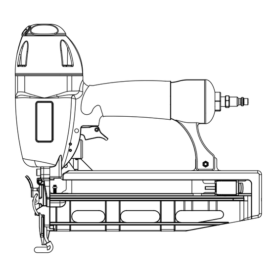
SOLUCIÓN DE PROBLEMAS PROBLEMA CAUSA POSIBLE SOLUCIÓN Fuga de aire cerca de la parte superior Tornillos sueltos Apriete los tornillos de la herramienta o junto al gatillo Juntas tóricas o sellos gastados o Instale el juego de mantenimiento dañados general Fuga de aire cerca de la parte inferior Juntas tóricas o tope gastados o da- Instale el juego de mantenimiento... - Page 41 Fig. 1 Fig. 4 A -Adjustable exhaust (échappement réglable, escape ajustable) Fig. 5 A - Workpiece contact (contact de déclenchement, disparador de contacto) B - No-mar nosepiece (coussinet de protection, almohadilla protectora) C - Jam release (déblocage, soltador) D - Adjustable exhaust (échappement réglable, escape ajustable) E - Trigger (gâchette, gatillo) F - Quick-connect air-fitting (embout pneumatique à...
- Page 42 Fig. 6 Fig. 10 Fig. 8 A - Pusher (poussoir, empujador) A - Trigger (gâchette, gatillo) B - Workpiece contact (contact Fig. 11 declénchement, disparador de contacto) A - Nails (clous, clovos) B - Pusher release (relâcher l’poussoir, soltar el Fig.
- Page 43 NOTES / NOTAS...
- Page 44 • HOW TO OBTAIN CUSTOMER OR TECHNICAL SUPPORT: To obtain Customer or Technical Support please contact us at 1-800-525-2579. RYOBI is a registered trademark of Ryobi Limited and is used pursuant to a license granted by Ryobi Limited. • PIÈCES ET SERVICE Avant de faire la demande de service ou l’achat de pièces de remplacement, veuillez obtenir le numéro de série du modèle à...
Need help?
Do you have a question about the YN250FSE and is the answer not in the manual?
Questions and answers