Table of Contents
Advertisement
Quick Links
Download this manual
See also:
Service Manual
OPERATORS MANUAL
0-NET DIESEL GENERATORS
22.0 KW EDE·:.&OHz 17.0 KW EDE·.&O:Hz
17 .. 0 KW EDE ·50.Hz 13.5 KW EDE-50 Hz
Single 31J
ree Phase
PUBLICATION NO. 053852
REVISION 4
DECEMBER 2012
~
WESTERBEKE
WESTERBEKE CORPORATION • 150 JOHN HANCOCK ROAD
MYLES STANDISH INDUSTRIAL PARK • TAUNTON MA 02780
WEBSITE:
WWW.
WESTERBEKE.COM
---
IVMMA Member National Marine Manufacturers Association
--
Advertisement
Table of Contents
Troubleshooting

Subscribe to Our Youtube Channel
Related Manuals for Westerbeke 22.0 KW EDE-60Hz


Summary of Contents for Westerbeke 22.0 KW EDE-60Hz
- Page 1 17 .. 0 KW EDE ·50.Hz 13.5 KW EDE-50 Hz Single 31J ree Phase PUBLICATION NO. 053852 REVISION 4 DECEMBER 2012 WESTERBEKE WESTERBEKE CORPORATION • 150 JOHN HANCOCK ROAD MYLES STANDISH INDUSTRIAL PARK • TAUNTON MA 02780 WEBSITE: WWW. WESTERBEKE.COM IVMMA Member National Marine Manufacturers Association...
- Page 2 Shut down the unit and do not restart until it has been inspected and repaired. A WARNING DECAL is provided by WESTERBEKE and should be fixed to a bulkhead near your engine or generator. WESTERBEKE also recommends installing CARBON MONOXIDE DETECTORS in the living/sleeping quarters of your vessel.
- Page 3 SAFETY INSTRUCTIONS INTRODUCTION PREVENT BURNS - FIRE Read this safety manual carefully. Most accidents are caused by failure to follow fundamental rules and WARNING: Fire can cause injury or death! precautions. Know when dangerous conditions exist and take the necessary precautions to protect yourself, your •...
- Page 4 SAFETY INSTRUCTIONS ACCIDENTAL STARTING TOXIC EXHAUST GASES WARNING: Accidental starting can cause injury WARNING: Carbon monoxide (CO) is a deadly gas! or death! • Ensure that the exhaust system is adequate to expel gases • Disconnect the battery cables before servicing the engine/ discharged from the engine.
- Page 5 SAFETY INSTRUCTIONS • Do not wear loose clothing or jewelry when servicing ABYC, NFPA AND USCG PUBLICATIONS FOR equipment; tie back long hair and avoid wearing loose INSTALLING DIESEL ENGINES jackets, shirts, sleeves, rings, necklaces or bracelets that Read the following ABYC, NFPA and USCG publications could be caught in moving parts.
- Page 6 INSTALLATION When installing WESTERBEKE engines and generators it is important that strict attention be paid to the following information: CODES AND REGULATIONS Strict federal regulations, ABYC guidelines, and safety codes must be complied with when installing engines and generators in a marine environment.
-
Page 7: Table Of Contents
TABLE OF CONTENTS Parts Identification oo ............2 Introduction ................. 3 Fuel, Engine Oil and Engine Coolant........Preparations for Initial Start-Up ......... 6 Digital Control Panel ........oo ..... 7 LCD Sequence ..............8 Digital Control Panei ............SA-B Remote Stop/Start Panel ...... -
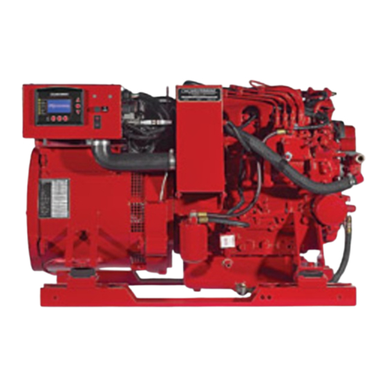
Page 8: Parts Identification Oo
PARTS IDENTIFICATION CONNECTIONS-~ REMOTE PANEl CONNECTION INTAKE ELBOW THER.MOSTAT ASSEMBLY DRIP TRAY LEFT SIDE FRONT Oil FILl COOLANT PRESSURE CAP. INJECTION PUMP HEAT EXCHANGER FUSL AIR INTAKE OIL FILTER CONTROL BOX AIR INTAKE SILENCER DIGITAL CONTROl SPIN-ON PANEL FUEL FILTER DC BREAKER RIGHT SIDE REAR... -
Page 9: Introduction
WESTERBEKE products, whether from WARRANTY PROCEDURES WESTERBEKE or other suppliers, must not and cannot Your WESTERBEKE Warranty is included in a separate · be relied upon exclusively as the definitive authority on folder. If, days of submittil;tg the Warranty Regiftry... - Page 10 INTRODUCTION NOTE: A carbon monoxide warning decal has been provided SERIAL NUMBER LOCATION by WESTERBEKE. Affix this decal in a visible position in the The engine's model number and serial number are located on engine room. an I.D. plate that is mounted on the side of the water jacketed exhaust manifold.
- Page 11 DIESEL FUEL, ENGINE OIL AND ENGINE COOLANT DIESEL FUEL ENGINE COOLANT WESTERBEKE recommends a mixture of 50% antifreeze USE A DIESEL FUEL WITH A CETANE RATING OF #45 OR HIGHER. and 50% distilled water. Distilled water is free from the (No.
-
Page 12: Preparations For Initial Start-Up
PREPARATIONS FOR INITIAL START ·UP PRESTART INSPECTION • Be sure that in power systems with a neutral line that Before starting your generator for the first time or after a pro- the neutral is properly grounded (or ungrounded) as the longed layoff, check the following items: system requires, and that the generator neutral is properly •... -
Page 13: Digital Control Panel
DIGITAL CONTROL PANEL DESCRIPTION LCD DISPLAY WESTERBEKE' S Digital Control Panel provides the Operating temperatures may cause the LCD display to vary operator with an LCD display that contunuously monitors in color. This is normal and a change.in color will not affect all the operations of the generator in easy to understand the operation on the control panel. -
Page 14: Lcd Sequence
DIGITAL CONTROL PANEL/LCD SEQUENCE START SEQUENCE STOP SEQUENCE With the pre-start inspection completed, press the START To stop the generator, press the STOP button. The display button and the automatic sequence will begin. The six will cycle thru the following text messages and shutdown. will indicator lights will illuminate green and the panel display the following text:... - Page 15 NMEA-2000 system or shut off the DC breaker on the generators control box for a WESTERLINK system. NOTE: Keep in mind that the Westerbeke generator maybe the DC power supply for the vessel's NMEA-2000 network. Engines &...
-
Page 16: Digital Control Panei
NMEA-2000 system or shut off the DC breaker on the generator's control box for a WESTERLINK system. vessel~· NOTE: Keep in mind that the Westerbeke generator maybe the DC power supply for the NMEA-2000 network. -
Page 17: Remote Stop/Start Panel
75' (22.17M). NOTE: For additionol information, contact your local WESTERBEKE dealer. CONNECTING EXTENSION CABLES 6" (152.4MM) . ·15' (4.75M) PN 052959 30' (9.1M) PN 052789 60' (18.2M) -
Page 18: Generator Break-In Procedure
DC breaker on the generator's control box for a When the engine is warm - almost Smokeless. WESTERLINK system. When the engine is overloaded - some Black Smoke. NOTE: Keep in mind that the Westerbeke generator maybe the DC power supply for the vessel's NMEA-2000 network. -
Page 19: Maintenance Schedule (Chart)
Check that all connections are tight. Engine Hoses Hose should be hard & tight. Replace if soft or spongy. Check and tighten all hose clamps. *WESTERBEKE recommends this service be performed by an authorized mechanic. (continued) Engines & Generators... - Page 20 NMEA-2000 system or shut off the DC breaker on the generators control box for a WESTERLINK system. NOTE: Keep in mind that the Westerbeke generator maybe the DC power supply for the vessel's NMEA-2000 network. Engines & Generators...
-
Page 21: Fuel System
This process is accomplished by installing and maintaining a proper fuel filter/water separator between the tank fuel and the generator/engine. Westerbeke recommends a 10 micron filter be used. FUEL LIFT PUMP FROM FUEL '\ L/FTPUMP... - Page 22 FUEL SYSTEM FUEL INJECTION PUMP BLEED SCREW The fuel injection pump is the most important component The bleed screw on the injection pump should be left in the of the diesel engine, requiring the utmost caution in handling. open position. This will then allow for ease in priming the The fuel injection pump has been thoroughly bench-tested engine's fuel system and during engine operation allow for and the owner/operator is cautioned not to attempt to service...
-
Page 23: Cooling System
COOLING SYSTEM DESCRIPTION Heat Exchanger Westerbeke marine diesel engines are designed and equipped The heat exchanger is a copper tube which encloses a number of small copper tubes. Raw water is pumped through for fresh water cooling. Heat produced in the engine by com-... - Page 24 COOLING SYSTEM. THERMOSTAT A thermostat, located near the manifold at the front of the engine, controls the coolant temperature as the coolant continuously flows through the closed cooling circuit. When the engine is first started, the closed thermostat pre- vents coolant from flowing (some coolant is by-passed through a hole in the thermostat to prevent the exhaust manifold from overheating).
- Page 25 COOLING SYSTEM FRESH WATER COOLING CIRCUIT CHANGING COOLANT The engine's coolant must be changed according to the NOTE: Refer to the ENGINE COOLANT section for the MAINTENANCE SCHEDULE. If the coolant is allowed to recommended antifreeze and water mixture to be used as the become contaminated, it can lead to overheating problems.
-
Page 26: Raw Water Cooling Circuit
COOLING SYSTEM RAW WATER COOLING CIRCUIT RAW WATER PUMP The raw water flow is created by a positive displacement #042175 impeller pump. This pump draws water directly from the ocean, lake, or river from a thru-hull opening through a hose to the water strainer. -
Page 27: Engine Lubricating Oil
ENGINE LUBRICATING OIL GASKET ENGINE OIL CHANGE APPLY CLEAN OIL TO SEALING GASKET 1. Draining the Oil Sump. Discharge the used oil through the sump drain hose (attached to the front of the engine) while the engine is warm. Drain the used oil completely, replace the hose in its brocket, and replace the end cap securely. -
Page 28: Testing Oil Pressure 00.00
OIL PRESSURE DESCRIPTION The lubricating system is a pressure feeding system using an oil pump. The engine oil is drawn from the oil sump by the oil pump, which drives the oil, under pressure, through TESTING OIL PRESSURE the oil filter, oil cooler and various lubricating points in the NOTE: To test the oil pressure, install a mechanical pressure engine. -
Page 29: Remote Oil Filter (Optional)Oooooooooooooo000Ooooooooooooooooo
PN.#054372 INSTALLATION NOTE: Westerbeke is not responsible for engine failure due to incorrect installation of the Remote Oil Filter. This popular accessory is used to relocate the engine's oil fil- ter from the engine to a more convenient location such as an engine room bulkhead. - Page 30 r - - - - ~~ll THISWIRENOTREQUIREDFORTHISAPPLICATION -+1. 12 VOLT WIRING DIAGRAM #53731 Ll;m CURR~~~Li!~S[ " \ ~~ t,}~l ~~ ~ ~ >~ • "a 8-f'OS rnMNAL El.OCK ® IN I 12WC ~Tl!RY ..~----~ < STATOR~ _ _j ---c-:-:-'-- : :a ,,a.Hlllflc~ SI'EEilliiEMOI...
- Page 31 , - - - - - - - - - 24 VOLT WIRING DIAGRAM #53829 r;;- VOlTSEMSE tAIILE (UAR~:'L~ENSE NOTE: t:::::. I. FIRE SUPRESSION SYSTEN CONNECTION IS NOT A POWER SOURCE. THIS CIRCUIT MUST CLOSED TO RUN. OPEN TO STOP GENSEl CS®...
- Page 32 c!NA.l::CK C::CTIO:-• - WIRING DIAGRAM #529\51 (12 VOLT} SHOWN ARE CONFIGUR(D fOR ·~ •I PAAALL{L·WY£ 1901Z08VAC REHR TO Sll28 FOR OTH[R u•u OPliOKS '101.1 CUIJI[II Ull( NOTES: c~&\{ II [lt(RUL ALAIN SIST[N COfUI[CTICI IS NOT A POilU $0URC[. CIRCUIT LOGIC IS CLOUD TO OP[H tO STOP G(IS[T.
-
Page 33: Engine Troubleshooting (Chart) Ooooooooooooooooooooooooooooooooooooooo.23
ENGINE TROUBLESHOOTING LCD DISPLAY FAULTS • (continued) Note: The engine's DC electrical system is protected by a 20 amp rocker type reset circuit breaker mounted on the control panel. Problem Probable Cause Verification/Remedy START BUTION depressed 1. Battery Switch not on. 1. - Page 34 ENGINE TROUBLESHOOTING LCD DISPLAY FAULTS PROBLEM PROBABLE CAUSE VERIFICATION/REMEDY LCD DISPLAY DOES 1. Check battery. 1. Battery on. NOT ILLUMINATE 2. 20 amp breaker off. 2. Turn breaker on. 3. Loose display connection. 3. Check all cable connections. 4. 1 amp fuse blown (faulty). 4.
- Page 35 A working alternator runs hot. A failed The following information applies to the standard alternators alternator can become very hot. Do not touch the that are supplied with WESTERBEKE' S Engines and Generators. alternator until if has cooled. ELECTRICAL CHARGING CIRCUIT...
- Page 36 ALTERNATORS TESTING/TROUBLESHOOTING MEASURING BATTERY VOLTAGE TESTING THE ALTERNATOR {IGNITION ON ENGINE OFF) CAUTION: Before starting the engine make certain that everyone is clear of moving parts! Keep away from sheaves and belts during test procedures. Start the Engine. 2. After the engine has run for a few minutes, measure the starting battery voltage at the battery terminals using a multimeter set on DC volts.
- Page 37 If tests indicate a failed alternator, it will need to be disas- sembled and repaired. Any good alternator service shop can do the job. NOTE: WESTERBEKE'S Service Manual has detailed instructions for the disassembly and repair of their standard alternators. BAnERYCARE...
-
Page 38: Engine Adjustments
ENGINE ADJUSTMENTS NOTE: WESTERBEKE recommends that the following engine adjust- ments be performed by a competent engine mechanic. The information below is provided to assist the mechanic. CHECKING VALVE CLEARANCE Valve clearance must be checked and adjusted when engine is cold. -
Page 39: Glow Plugs
ENGINE ADJUSTMENTS DRIVE BELT ADJUSTMENT Proper inspection, service and maintenance of the drive belts is important for the efficient operation of your engine (see GLOW PLUG Drive Belts under MAINTENANCE SCHEDULE). CONNECTION STRAP Drive belts must be properly tensioned. Loose d1ive belts will not provide proper alternator charging and will eventually damage the alternator. -
Page 40: Fuel Injectors
FUEL INJECTORS Inspecting Spray Pattern REMOVING THE INJECTORS Operate the hand lever of the nozzle tester at intervals of NOTE: Injector must be serviced in a "clean room" emirmunent. one stroke per second to check if the fuel is injected cor- Disconnect the high pressure lines from the injectors and rectly in its axial direction. -
Page 41: Troubleshooting
STARTER MOTOR TROUBLESHOOTING Prior to testing, make certain the ships batteries are at full charge and that the starting system wiring connections (terminals) are clean and tight. Pay particular attention to the ground wire connections on the engine block. To check the wiring, cranking the starter for a few seconds, never more than 10 seconds at a time, then run your hand along the wires and terminals looking for warm spots... - Page 42 When you reach a repair facility, the starter will need to be repaired. SERVICE WESTERBEKE uses a standard starter motor which can be REFER TO THR WIRING serviced or rebuilt at any starter motor automotive service...
- Page 43 SPECIFICATIONS 22.0/17.0 EDE ENGINE SPECIFICATIONS COOLING SYSTEM Engine Type Diesel, four-cycle, four-cylinder, fresh General Fresh water-cooled engine block, water-cooled, vertical in-line overhead valve thermostatically-controlled with heat exchanger. mechanism (35.5 hp at 1800 rpm maximum) Operating Temperature 160-180° F (71 -82° C) Aspiration Naturally aspirated Fresh Water Pump...
- Page 44 SPECIFICATIONS 17.0/13.5 EDE ENGINE SPECIFICATIONS LUBRICATION SYSTEM Engine Type Diesel, four-cycle, three-cylinder, fresh Operating Oil Pressure 28 - 57 psi (2.0 - 4.0 kg/em') water-cooled, vertical in-line overhead valve (engine hot) mechanism. Oil Grade Specification CF, CG-4, CF-4, CH-4, CI-4 Aspiration Naturally aspirated SAE IOW-40...
- Page 45 GENERATOR SPECIFICATION 3 PHASE 17.0/13.5 EDE 22.0/17.0 EDE AC GENERATOR (3 Phase) AC GENERATOR (3 Phase) Three Phase Brushless, six- pole, revolving field. Sealed Three Phase Brushless, six- pole, revolving field. Sealed 17.0 Kw- 60 Hertz lubricated, single-bearing design. 12 Lead 22.0 Kw - 60 Hertz lubricated, single-bearing design.
-
Page 46: Generator Lnformation
(split-phase) are not CARBON MONOXIDE DETECTOR made in larger sizes. WESTERBEKE recommends mounting a carbon monoxide Because the heavy surge of current needed for starting detector in the living quarters. Carbon Monoxide, even in motors is required for only an instant, the generator will not small amounts is deadly. -
Page 47: Electronic Regulation Oo•Oo•Oooo•Oo·oo
ELECTRONIC REGULATION #052944 5 AMP FUSE ADJUSTABLE THRESH PN #052951 l=:l OVERLOAD PROTECT/0 ·D/~ INTERVENTION liJon~~ p-.--; ADJUSTABLE THRESHOLD Z---'. OF UNDERSPEED -----tCONNECT FOR 60Hz INTERVENTION~ PROTECTION . Stab l-oi ~ :t ___J REMOVE FOR 50Hz volt -------:; _,I~ 1$,. !"'-t -:==J EXCITER FIELD... - Page 48 ELECTRONIC REGULATION #052944 TERMINAL BLOCK CONNECTIONS SHOWN ARE CONFIGUREO FOR LO·WYE 110/108 VAC TERI.INAL ElOCK Hertz: With this potentiometer, which is normally pre-calibrated then sealed by the manufacturer, it is possible to adjust the low frequency protection intervention. To recalibrate this protection, you must take the generator to a normal zero load condition, tum the potentiometer clockwise until the limit position is reached, then decrease REFER TO THE COMPLETE...
-
Page 49: Generator Wiring Schematics Oooooooooooooooooooo
GENERATOR WIRING SCHEMATICS r-----------~ : _A EXCITER STATOR . : CONDENSER i-8--:----c----~ I r-;----~ 10 STATOR : EXCITER : ROTOR FIELD ROTOR BLUE ... 5 I . DIDOES _T~E~~s_- ~~E~~ L - - - - _ _ _ _ _ _ _ _ _ _j . - Page 50 INTERNAL WIRING SCHEMATIC EXCITER ROTOR/ROTATING FIELD TRANSIENT CONDENSER ,------------ EXCITER ROTOR WINDINGS ------------- ----..J ~------ Erygines & Generators...
- Page 51 TWELVE LEAD WINDING/TERMINAL BOARD CONNECTIONS AND (NOMINAL) VOLTAGES (SERIES WYE) (PARALLEL WYE) SERIES SERIES PARALLEL DELTA STAR STAR ---~ 10-11 10-12 ·o 10..:11 4-8-12 1-12 50 Hz L-L 230 volts 50 Hz L-L 400 volts 50 Hz L-L 200 volts 50 Hz t-N 115 volts 50 Hz L-N 230 volts 50 Hz L-N 115 volts...
- Page 52 Reference the illustration on this page. Using the EC20 Monitoring Software forD-Net models. (available from the Westerbeke Distributor). Connect your laptop with the software installed to the communication pins on the ECU using the #055351 communications cable connected between your laptop and the ECU.
-
Page 53: Be Troubleshooting (Chart)
BE TROUBLESHOOTING NOTE: AC generator troubleshooting must be performed with the generator operating at the correct hertz. FAULT PROBABLE CAUSE NO AC VOLTAGE OUTPUT AT NO LOAD. 1. Short or open in the 4. Open in exciter main stator winding. stator winding. -
Page 54: Exciter Rotor Troubleshooting Oo
EXCITER ROTOR TROUBLESHOOTING LOW VOLTAGE • EXCITER ROTOR TESTING THE EXCITER ROTOR WINDINGS AND ROTATING FIELD These windings are tested in pairs: A B, B C, and C as shown on the drawing. Position the exciter rotor/rotating field so the transient suppressor is visible at the 12 O'Clock position. -
Page 55: Generator Servicing 00 Oooooo
GENERATOR . SERVICING TESTING THE MAGNETIC PICK UP COIL MAGNETIC PICK·UP [MPU] INSTALLATION Test the speed sensor connector for voltage and resistance The MPU is installed in the threaded opening on the side values. of the flywheel bellhousing. This positions the MPU over the teeth of the flywheel ring gear. - Page 56 BE GENERATOR MAINTENANCE/PARTS BREAKDOWN INSPECTION/CLEANING Periodically inspect the rotor carrier bearing. Replace this Remove all dirt, oil, grease and dust build up from the bearing at 10,000 hours of normal operation or sooner if external surface of the generator. Build-up reduces heat wear is evident.
- Page 57 BE GENERATOR ASSEMBLY OF THE GENERATOR TO THE ENGINE Rotate the generator by hand two full revolutions to Position the rotor assembly onto the flywheel aligning the · ensu.re the generator rotates freely. Reinstall the rear holes in the drive discs with the holes in the flywheel. vent cover.
- Page 58 SHORE POWER TRANSFER SWITCH CONNECTIONS GENERATOR -=;,. DESCRIPTION NOTE: Diagram shows connections for a two- If the installer connects shore power to the vessel's AC cir- wire, 120-Volt system from the generator. with three-wire,120-Volt boat system. cuit, this must be done by means of the SHORE POWER GENERATORiSHORE OFF SHIPS GEN.
- Page 59 LAY·UP & RECOMMISSIONING GENERAL Fuel System [Gasoline] Many owners rely on their boatyards to prepare their craft, Top off your fuel tanks with unleaded gasoline of 89 octane including engines and generators, for lay-up during the or higher. A fuel conditioner such as Sta-Bil gasoline off-season or for long periods of inactivity.
-
Page 60: Lay-Up And Recommissioning
Lay-up time provides a good opportunity to inspect your if access to the starter permits its easy removal. Make sure the Westerbeke engine to see if external items such as drive belts battery connections are shut off before attempting to remove or coolant hoses need replacement. -
Page 61: Water Heater Connections. 00
WATER HEATER CONNECTIONS WATER HEATER INSTALLATIONS These engines are equipped with connections for the plumbing WATER HEATER CONNECTIONS of engine coolant to transfer heat to an on·board water hea,:et. · ANi)- CONNECT HOSES TO The water heater should be mounted in a convenient locatiorl FROM THE HOT WATER HEATER either in a high or low position in relation to the engine, so AS SHOWN HERE. - Page 62 DECIMAL TO METRIC EQUIVALENT CHART Fractions of Fractions of Metric (mm) Decimal (in.) Metric (mm) Decimal (in.) an inch an inch 1/64 0.39688 33/64 0.515625 13.09687 0.015625 13.49375 1/32 0.03125 0.79375 17/32 0.53125 3/64 35/64 0.546875 13.89062 0.046875 1.19062 1/16 0.0625 1.58750 9116...
-
Page 63: Metric Conversion Data (Chart)
STANDARD AND METRIC CONVERSION DATA LENGTH-DISTANCE Inches (in) x 25.4 = Millimeters (mm) x .0394 = Inches Feet (ft) x .305 = Meters (m) x 3.281 = Feet Miles x 1.609 = Kilometers (km) x .0621 = Miles DISTANCE EQUIVALENTS 1 Degree of Latitude = 60 Nm = 111.120 km 1 Minute of Latitude = 1 Nm = 1.852 km VOLUME... - Page 64 SUGGESTED SPARE PARTS WESTERBEKE MARINE GENERATORS CONTACT YOUR WESTERBEKE DEALER FOR SUGGESTIONS AND ADDITIONAL INFORMATION HARDWARE KIT IN·LINE FUEL FILTERS (OWNER INSTALLED) .SA FUSE (ON FRONT MOLDED OF THE CONTROL PANEL) HOSE KIT WESTERBEKE RECOMMENDS HAVING ENOUGH SPARE IN A CANVAS ENGINE OIL (YOUR BRAND) FOR AN OIL CHANGE (5 QTS.)
- Page 66 Engines & Generators 12/2012-1180...
Need help?
Do you have a question about the 22.0 KW EDE-60Hz and is the answer not in the manual?
Questions and answers