Mitsubishi Electric Mr. Slim MXZ-2A20NA Service Manual
Split-type outdoor unit
Hide thumbs
Also See for Mr. Slim MXZ-2A20NA:
- Installation manual (9 pages) ,
- Installation manual (10 pages) ,
- Service manual (88 pages)
Table of Contents
Advertisement
SPLIT-TYPE AIR CONDITIONERS
OUTDOOR UNIT
SERVICE MANUAL
Models
MXZ-2A20NA
MXZ-2A20NA -
MXZ-2A20NA -
MXZ-3A30NA
MXZ-3A30NA -
MXZ-4A36NA
NOTE:
• This service manual describes technical
data of the outdoor units.
• RoHS compliant products have <G> mark
on the spec name plate.
For servicing of RoHS compliant products,
refer to the RoHS Parts List.
1
2
1
MXZ-2A20NA
MXZ-2A20NA -
1
9700058
Revision G:
• SPECIFICATION, NOISE CRITERIA CURVES
and OPTIONAL PARTS have been modified.
Please void OB444 REVISED EDITION-F.
HFC
utilized
R410A
Indoor unit service manual
MSZ-A·NA Series (OB450)
SEZ-KD·NA.TH Series
CONTENTS
1. TECHNICAL CHANGES· ·································· 2
2. PART NAMES AND FUNCTIONS ····················· 6
3. INDOOR UNITS COMBINATION ······················ 7
4. SPECIFICATION ·············································· 43
5. NOISE CRITERIA CURVES ···························· 46
6. OUTLINES AND DIMENSIONS ······················ 47
7. WIRING DIAGRAM ·········································· 52
8. REFRIGERANT SYSTEM DIAGRAM ············· 58
9. DATA ································································ 64
10. ACTUATOR CONTROL ··································· 80
11. SERVICE FUNCTIONS ···································· 80
12. TROUBLESHOOTING ····································· 82
13. DISASSEMBLY INSTRUCTIONS ·················· 100
14. PARTS LIST ····················································112
15. RoHS PARTS LIST ········································ 120
16. OPTIONAL PARTS ········································ 136
The Slim Line.
From Mitsubishi Electric.
33223
No. OB444
REVISED EDITION-G
TM
Advertisement
Table of Contents
Troubleshooting

Related Manuals for Mitsubishi Electric Mr. Slim MXZ-2A20NA


Summary of Contents for Mitsubishi Electric Mr. Slim MXZ-2A20NA
-
Page 1: Table Of Contents
Please void OB444 REVISED EDITION-F. OUTDOOR UNIT No. OB444 SERVICE MANUAL REVISED EDITION-G utilized R410A Models MXZ-2A20NA MXZ-2A20NA - MXZ-2A20NA - MXZ-3A30NA MXZ-3A30NA - Indoor unit service manual MSZ-A·NA Series (OB450) MXZ-4A36NA SEZ-KD·NA.TH Series CONTENTS 1. TECHNICAL CHANGES· ·································· 2 2. -
Page 2: Technical Changes
• MXZ-4A36NA has been added. Revision D: • MXZ-2A20NA - has been added. Revision E: • Wiring diagrams of MXZ-2A20NA - MXZ-4A36NA have been corrected. Revision F: • Indoor units combinations for SEZ series have been added. Revision G: • SPECIFICATION, NOISE CRITERIA CURVES and OPTIONAL PARTS have been modified. - Page 3 MXZ-4A36NA New model MXZ-2A20NA - MXZ-2A20NA - 1. Electronic control P.C. board has been changed. 2. Noise filter P.C. board has been changed. 3. Ball valve has been changed to stop valve. 4. Sub panel has been added. INFORMATION FOR THE AIR CONDITIONER WITH R410A REFRIGERANT •...
- Page 4 New Specification Current Specification The incompatible refrigeration oil easily separates from Since refrigerant and refrigeration oil are compatible, refrigerant and is in the upper layer inside the suction muffler. refrigeration oil goes back to the compressor through the Raising position of the oil back hole enables to back the lower position oil back hole.
- Page 5 2. Refrigerant piping Specifications Use the copper or copper-alloy seamless pipes for refrigerant that meet the following specifications. Outside diameter Wall thickness Insulation material (inch) (inch) 0.0315 0.0315 Heat resisting foam plastic 0.0315 Specific gravity 0.045 Thickness 0.315 inch 0.0394 Flaring work and flare nut Flaring work for R410A pipe differs from that for R22 pipe.
-
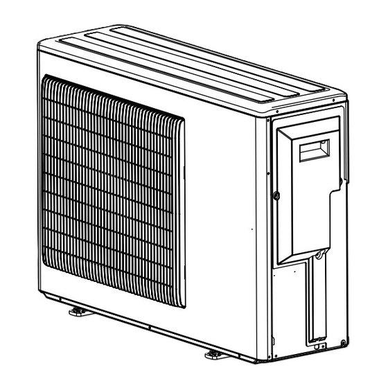
Page 6: Part Names And Functions
PART NAMES AND FUNCTIONS MXZ-2A20NA MXZ-2A20NA - MXZ-2A20NA - Air inlet Air inlet (Back and side) (Back and side) Air outlet Air outlet Drain outlet Drain outlet MXZ-3A30NA - MXZ-4A36NA MXZ-3A30NA Air inlet Air inlet (Back and side) (Back and side) -
Page 7: Indoor Units Combination
INDOOR UNITS COMBINATION MXZ-2A20NA MXZ-2A20NA - MXZ-2A20NA- Cooling Power Indoor type Cooling capacity (BTU/h) Current(A) Indoor units Power consumption factor combination Unit A Unit B Total 208V 230V Wall — 9000 — 9000 3.69 3.34 5400 9000 Duct — 9000 —... - Page 8 MXZ-2A20NA MXZ-2A20NA - MXZ-2A20NA- Heating Power Indoor type Heating capacity (BTU/h) Current(A) Indoor units Power consumption factor combination Unit A Unit B Total 208V 230V Wall — 10900 — 10900 4.76 4.30 5200 15400 ) ( 1430 Duct — 10900 —...
- Page 9 MXZ-3A30NA MXZ-3A30NA - Cooling Power Indoor type Cooling capacity (BTU/h) Current(A) Indoor units Power consumption factor combination Unit A Unit B Unit C Total 208V 230V Wall — — 9000 — — 9000 4.05 3.66 7200 9000 Duct — — 9000 —...
- Page 10 Power Indoor type Cooling capacity (BTU/h) Current(A) Indoor units Power consumption factor combination Unit A Unit B Unit C Total 208V 230V Wall Wall — 7600 20400 — 28000 3200 15.86 14.34 ( 12000 - 28000 ) ( 3200 09+24 Duct Wall —...
- Page 11 Power Indoor type Cooling capacity (BTU/h) Current(A) Indoor units Power consumption factor combination Unit A Unit B Unit C Total 208V 230V Wall Wall Wall 9000 9000 9000 27000 2860 14.18 12.82 ( 12600 - 27000 ) ( 1000 2860 Wall Wall Duct 9000...
- Page 12 MXZ-3A30NA MXZ-3A30NA - Heating Power Indoor type Heating capacity (BTU/h) Current(A) Indoor units Power consumption factor combination Unit A Unit B Unit C Total 208V 230V Wall — — 10900 — — 10900 1100 5.57 5.03 8600 - 15400 ) ( 1520 Duct —...
- Page 13 Power Indoor type Heating capacity (BTU/h) Current(A) Indoor units Power consumption factor combination Unit A Unit B Unit C Total 208V 230V Wall Wall — 7300 19700 — 27000 1980 9.81 8.87 ( 11000 - 35000 ) ( 2740 09+24 Duct Wall —...
- Page 14 Power Indoor type Heating capacity (BTU/h) Current(A) Indoor units Power consumption factor combination Unit A Unit B Unit C Total 208V 230V Wall Wall Wall 9500 9500 9500 28500 2180 10.80 9.77 ( 11400 - 36000 ) ( 2880 Wall Wall Duct 9500 9500...
- Page 15 MXZ-4A36NA 208V Cooling Current(A) Power Indoor type Cooling capacity (BTU/h) Indoor units Power consumption factor combination Unit A Unit B Unit C Unit D Total 208V Wall — — — 9000 — — 9000 4.05 ( 7200 - 9000 ) ( Duct —...
- Page 16 Current(A) Power Indoor type Cooling capacity (BTU/h) Indoor units Power consumption factor combination Unit A Unit B Unit C Unit D Total 208V Wall Wall — — 12000 12000 — — 24000 2500 12.39 ( 12000 - 24000 ) ( - 2500 ) Wall Duct —...
- Page 17 Current(A) Power Indoor type Cooling capacity (BTU/h) Indoor units Power consumption factor combination Unit A Unit B Unit C Unit D Total 208V Wall Wall Wall — 9000 9000 12000 — 30000 3270 16.21 ( 12600 - 30000 ) ( 1000 - 3270 ) Wall Wall Duct —...
- Page 18 Current(A) Power Indoor type Cooling capacity (BTU/h) Indoor units Power consumption factor combination Unit A Unit B Unit C Unit D Total 208V Wall Wall Wall — 8000 10700 13400 — 32100 3500 17.35 ( 12600 - 32100 ) ( 1000 - 3500 ) Wall Wall Duct —...
- Page 19 Current(A) Power Indoor type Cooling capacity (BTU/h) Indoor units Power consumption factor combination Unit A Unit B Unit C Unit D Total 208V Wall Wall Duct — 7000 11600 13500 — 32100 3520 17.45 ( 12600 - 32100 ) ( 1020 - 3520 ) Wall Duct Duct —...
- Page 20 Current(A) Power Indoor type Cooling capacity (BTU/h) Indoor units Power consumption factor combination Unit A Unit B Unit C Unit D Total 208V Wall Wall Wall — 9100 11500 11500 — 32100 3500 17.35 ( 12600 - 32100 ) ( 1000 - 3500 ) Wall Wall Duct —...
- Page 21 Current(A) Power Indoor type Cooling capacity (BTU/h) Indoor units Power consumption factor combination Unit A Unit B Unit C Unit D Total 208V Wall Wall Wall Wall 7700 7700 10300 10300 36000 3820 18.55 ( 12600 - 36400 ) ( 1000 - 3900 ) Wall Wall Wall Duct...
- Page 22 MXZ-4A36NA 230V Cooling Current(A) Power Indoor type Cooling capacity (BTU/h) Indoor units Power consumption factor combination Unit A Unit B Unit C Unit D Total 230V Wall — — — 9000 — — — 9000 3.66 ( 7200 - 9000 ) ( Duct —...
- Page 23 Current(A) Power Indoor type Cooling capacity (BTU/h) Indoor units Power consumption factor combination Unit A Unit B Unit C Unit D Total 230V Wall Wall — — 12000 12000 — — 24000 2500 11.21 ( 12000 - 24000 ) ( - 2500 ) Wall Duct —...
- Page 24 Current(A) Power Indoor type Cooling capacity (BTU/h) Indoor units Power consumption factor combination Unit A Unit B Unit C Unit D Total 230V Wall Wall Wall — 9000 9000 12000 — 30000 3270 14.66 ( 12600 - 30000 ) ( 1000 - 3270 ) Wall Wall Duct —...
- Page 25 Current(A) Power Indoor type Cooling capacity (BTU/h) Indoor units Power consumption factor combination Unit A Unit B Unit C Unit D Total 230V Wall Wall Wall — 8000 10700 13400 — 32100 3500 15.69 ( 12600 - 32100 ) ( 1000 - 3500 ) Wall Wall Duct —...
- Page 26 Current(A) Power Indoor type Cooling capacity (BTU/h) Indoor units Power consumption factor combination Unit A Unit B Unit C Unit D Total 230V Wall Wall Duct — 7000 11600 13500 — 32100 3520 15.78 ( 12600 - 32100 ) ( 1020 - 3520 ) Wall Duct Duct —...
- Page 27 Current(A) Power Indoor type Cooling capacity (BTU/h) Indoor units Power consumption factor combination Unit A Unit B Unit C Unit D Total 230V Wall Wall Wall — 9100 11500 11500 — 32100 3500 15.69 ( 12600 - 32100 ) ( 1000 - 3500 ) Wall Wall Duct —...
- Page 28 Current(A) Power Indoor type Cooling capacity (BTU/h) Indoor units Power consumption factor combination Unit A Unit B Unit C Unit D Total 230V Wall Wall Wall Wall 7700 7700 10300 10300 36000 3820 16.78 ( 12600 - 36400 ) ( 1000 - 3900 ) Wall Wall Wall Duct...
- Page 29 MXZ-4A36NA 208V Heating Current(A) Power Indoor type Heating capacity (BTU/h) Indoor units Power consumption factor combination Unit A Unit B Unit C Unit D Total 208V Wall — — — 10900 — — — 10900 1100 5.57 ( 8600 - 15400 ) ( - 1520 ) Duct —...
- Page 30 Current(A) Power Indoor type Heating capacity (BTU/h) Indoor units Power consumption factor combination Unit A Unit B Unit C Unit D Total 208V Wall Wall — — 13500 13500 — — 27000 2200 10.90 ( 11000 - 35000 ) ( - 2920 ) Wall Duct —...
- Page 31 Current(A) Power Indoor type Heating capacity (BTU/h) Indoor units Power consumption factor combination Unit A Unit B Unit C Unit D Total 208V Wall Wall Wall — 10000 10000 12400 — 32400 2700 13.38 ( 11400 - 36000 ) ( - 2880 ) Wall Wall Duct...
- Page 32 Current(A) Power Indoor type Heating capacity (BTU/h) Indoor units Power consumption factor combination Unit A Unit B Unit C Unit D Total 208V Wall Wall Wall — 8300 10400 13700 — 32400 2700 13.38 ( 11400 - 36000 ) ( - 2880 ) Wall Wall Duct...
- Page 33 Current(A) Power Indoor type Heating capacity (BTU/h) Indoor units Power consumption factor combination Unit A Unit B Unit C Unit D Total 208V Wall Wall Duct — 7100 11900 13400 — 32400 2700 13.38 ( 11400 - 36000 ) ( - 2880 ) Wall Duct Duct —...
- Page 34 Current(A) Power Indoor type Heating capacity (BTU/h) Indoor units Power consumption factor combination Unit A Unit B Unit C Unit D Total 208V Wall Wall Wall — 9000 11700 11700 — 32400 2700 13.38 ( 11400 - 36000 ) ( - 2880 ) Wall Wall Duct...
- Page 35 Current(A) Power Indoor type Heating capacity (BTU/h) Indoor units Power consumption factor combination Unit A Unit B Unit C Unit D Total 208V Wall Wall Wall Wall 7700 7700 10300 10300 36000 3100 15.05 ( 11400 - 41200 ) ( - 4000 ) Wall Wall...
- Page 36 MXZ-4A36NA 230V Haeting Current(A) Power Indoor type Heating capacity (BTU/h) Indoor units Power consumption factor combination Unit A Unit B Unit C Unit D Total 230V Wall — — — 10900 — — — 10900 1100 5.03 ( 8600 - 15400 ) ( - 1520 ) Duct —...
- Page 37 Current(A) Power Indoor type Heating capacity (BTU/h) Indoor units Power consumption factor combination Unit A Unit B Unit C Unit D Total 230V Wall Wall — — 13500 13500 — — 27000 2200 9.86 ( 11000 - 35000 ) ( - 2920 ) Wall Duct —...
- Page 38 Current(A) Power Indoor type Heating capacity (BTU/h) Indoor units Power consumption factor combination Unit A Unit B Unit C Unit D Total 230V Wall Wall Wall — 10000 10000 12400 — 32400 2700 12.10 ( 11400 - 36000 ) ( - 2880 ) Wall Wall Duct...
- Page 39 Current(A) Power Indoor type Heating capacity (BTU/h) Indoor units Power consumption factor combination Unit A Unit B Unit C Unit D Total 230V Wall Wall Wall — 8300 10400 13700 — 32400 2700 12.10 ( 11400 - 36000 ) ( - 2880 ) Wall Wall Duct...
- Page 40 Current(A) Power Indoor type Heating capacity (BTU/h) Indoor units Power consumption factor combination Unit A Unit B Unit C Unit D Total 230V Wall Wall Duct — 7100 11900 13400 — 32400 2700 12.10 ( 11400 - 36000 ) ( - 2880 ) Wall Duct Duct —...
- Page 41 Current(A) Power Indoor type Heating capacity (BTU/h) Indoor units Power consumption factor combination Unit A Unit B Unit C Unit D Total 230V Wall Wall Wall — 9000 11700 11700 — 32400 2700 12.10 ( 11400 - 36000 ) ( - 2880 ) Wall Wall Duct...
- Page 42 Current(A) Power Indoor type Heating capacity (BTU/h) Indoor units Power consumption factor combination Unit A Unit B Unit C Unit D Total 230V Wall Wall Wall Wall 7700 7700 10300 10300 36000 3100 13.61 ( 11400 - 43000 ) ( - 4350 ) Wall Wall...
-
Page 43: Specification
SPECIFICATION Outdoor model MXZ-2A20NA MXZ-2A20NA - MXZ-2A20NA - Item Indoor type Wall Duct Cooling 20,000/ (7,800 ~ 20,000) 20,000/ (7,800 ~ 20,000) Btu/h 22,000/ (8,500 ~ 22,000) 22,000/ (8,500 ~ 22,000) Capacity Heating 47 Btu/h 14,500 12,500 Heating 17 Btu/h... - Page 44 Outdoor model MXZ-3A30NA MXZ-3A30NA - Indoor type Wall Duct Item Cooling Btu/h 28,400/ (12,600 ~ 28,400) 27,400/ (12,600 ~ 27,400) Capacity Heating 47 Btu/h 28,600/ (11,400 ~ 36,000) 27,600/ (11,400 ~ 35,000) Heating 17 Btu/h 18,800 18,000 Cooling 3,250/ (1,000 ~ 3,250) 3,330/ (1,060 ~ 3,330) Power Heating 47...
- Page 45 Outdoor model MXZ-4A36NA Wall Duct Indoor type Item Cooling Btu/h 36,000/ (12,600 ~ 36,400) 34,400/ (12,600 ~ 34,800) 208 V 36,000/ (11,400 ~ 41,200) 208 V 34,400/ (11,400 ~ 39,600) Capacity Heating 47 Btu/h 230 V 36,000/ (11,400 ~ 43,000) 230 V 34,400/ (11,400 ~ 41,600) Heating 17...
-
Page 46: Noise Criteria Curves
NOISE CRITERIA CURVE MXZ-2A20NA MXZ-3A30NA FAN SPEED FUNCTION SPL(dB LINE FAN SPEED FUNCTION SPL(dB LINE High Cooling High Cooling High Heating High Heating NC-70 NC-70 NC-60 NC-60 NC-50 NC-50 NC-40 NC-40 NC-30 NC-30 APPROXIMATE APPROXIMATE THRESHOLD OF THRESHOLD OF HEARING FOR... -
Page 47: Outlines And Dimensions
OUTLINES AND DIMENSIONS Unit: inch MXZ-2A20NA MXZ-2A20NA - REQUIRED SPACE Open as a rule More than 19.69 in. if the front and both sides are 6-9/16" 19-11/16" 6-21/32" open 9-3/16" 11-11/32" 2-1/2" More than 3.94 in. More than 3.94 in. -
Page 48: Installation Space
MXZ-2A20NA - Unit: inch 6-9/16" 19-11/16" 6-21/32" 2-1/2" 9-3/16" 11-11/32" Rear Air Intake Side Air Intake 3- (1-5/16") Drain Hole Discharge 4-(13/32"×13/16") Oval Hole (Foundation Bolt M10) 33-1/16" 1-3/16" 7-7/8" 1-3/16" 13" 1/2" 3- 7/8" Punched holes (Connecting wire hole) 1-5/32"... - Page 49 MXZ-3A30NA Unit: inch REQUIRED SPACE Open as a rule More than 19.69 in. if the front and both sides are open 7-7/8" 19-11/16" (7-7/8") More than 3.94 in. More than 3.94 in. 9-27/32" More than 7.87 in. 1-3/8" 10-5/8" if there are obstacles to both sides 2-U-shape notched holes...
- Page 50 MXZ-3A30NA - Unit: inch 7-7/8" 19-11/16" 7-7/8" 9-27/32" 10-5/8" 2-U Shaped notched hole 1-3/8" (Base bolt M10) Air in Air in Drain hole 3- 1-5/16" Air out 2-(15/32" x 1-13/32") Oval hole (Base bolt M10) 3- 7/8"Punched hole (Connect wiring hole) 1-3/16"...
- Page 51 MXZ-4A36NA Unit: inch 7-7/8" 19-11/16" 7-7/8" 9-27/32" 10-5/8" 2-U Shaped notched hole 1-3/8" (Base bolt M10) Air in Air in Drain hole 3- 1-5/16" Air out 2-(15/32" x 1-13/32") Oval hole (Base bolt M10) 3- 7/8"Punched hole (Connect wiring hole) 1-3/16"...
-
Page 52: Wiring Diagram
WIRING DIAGRAM MXZ-2A20NA... - Page 53 MXZ-2A20NA -...
- Page 54 MXZ-2A20NA -...
- Page 55 MXZ-3A30NA...
- Page 56 MXZ-3A30NA -...
- Page 57 MXZ-4A36NA...
-
Page 58: Refrigerant System Diagram
LEV E #100 #100 Distributor Power receiver Capillary tube O.D.0.16 x I.D.0.11 x 3.93 Indoor unit LEV B Strainer #100 * Except MXZ-2A20NA - MXZ-2A20NA - Service port Compressor R.V. coil Discharge Service temperature Refrigerant flow in cooling port thermistor RT62... - Page 59 Operating Range MXZ-2A20NA MXZ-2A20NA - MXZ-2A20NA - Indoor intake air temperature Outdoor intake air temperature Maximum 95°FDB, 71°FWB 115°FDB Cooling Minimum 67°FDB, 57°FWB 14°FDB Maximum 80°FDB, 67°FWB 75°FDB, 65°FWB Heating Minimum 70°FDB, 60°FWB 14°FDB, 12°FWB MAX. REFRIGERANT PIPING LENGTH & PIPE SIZE SELECTION...
- Page 60 Service MXZ-3A30NA Unit: mm port Service Compressor R.V. coil port Discharge High-pressure Refrigerant flow in cooling temperature switch Refrigerant flow in heating thermistor RT62 Oil separator Capillary tube O.D.0.10 x I.D.0.02 x 39.37 Unit C gas pipe Ball valve with temperature thermistor Indoor unit service port...
- Page 61 Operating Range MXZ-3A30NA MXZ-3A30NA - Indoor intake air temperature Outdoor intake air temperature Maximum 95°FDB, 71°FWB 115°FDB Cooling Minimum 67°FDB, 57°FWB 14°FDB Maximum 80°FDB, 67°FWB 75°FDB, 65°FWB Heating Minimum 70°FDB, 60°FWB 14°FDB, 12°FWB MAX. REFRIGERANT PIPING LENGTH & PIPE SIZE SELECTION MXZ-3A30NA MXZ-3A30NA - Piping length each indoor unit (a, b, c) 82 ft.
- Page 62 MXZ-4A36NA Unit: mm Service port Compressor Service Discharge port R.V. coil temperature High-pressure Refrigerant flow in cooling thermistor RT62 switch Refrigerant flow in heating Oil separator Capillary tube Indoor unit O.D.0.10 x I.D.0.02 x 39.37 Stop valve 4-way valve (with service port) Indoor unit Indoor unit Muffler...
- Page 63 Operating Range MXZ-4A36NA Indoor intake air temperature Outdoor intake air temperature Maximum 95°FDB, 71°FWB 115°FDB Cooling Minimum 67°FDB, 57°FWB 14°FDB Maximum 80°FDB, 67°FWB 75°FDB, 65°FWB Heating Minimum 70°FDB, 60°FWB 14°FDB, 12°FWB MAX. REFRIGERANT PIPING LENGTH & PIPE SIZE SELECTION MXZ-4A36NA Piping length each indoor unit (a, b, c, d) 82 ft.
-
Page 64: Data
DATA MXZ-2A20NA MXZ-2A20NA- MXZ-2A20NA- Model Indoor type Wall Duct Item Unit Cooling Heating Cooling Heating Total Capacity But/h 20,000 22,000 20,000 22,000 – – – – – Input 2.15 1.78 2.19 1.78 Electrical Outdoor unit MXZ-2A20NA MXZ-2A20NA- MXZ-2A20NA- circuit Power supply (V,phase,Hz) - Page 65 MXZ-3A30NA MXZ-3A30NA- Model Indoor type Wall Duct Item Unit Cooling Heating Cooling Heating Total Capacity But/h 28,400 28,600 27,400 27,600 – – – – – Input 3.25 2.18 3.33 2.22 Electrical Outdoor unit MXZ-3A30NA MXZ-3A30NA- circuit Power supply (V,phase,Hz) 208/230,1,60 Input 3.197 2.127...
- Page 66 MXZ-4A36NA Model Indoor type Wall Duct Item Unit Cooling Heating Cooling Heating Total Capacity But/h 36,000 36,000 34,400 34,400 – – – – – Input 3.82 3.94 Electrical Outdoor unit MXZ-4A36NA circuit Power supply (V,phase,Hz) 208/230,1,60 Input 3.756 3.036 3.62 2.86 Comp.
- Page 67 9-1. OPERATING RANGE (1) POWER SUPPLY Rating Guaranteed Voltage Model MXZ-2A20NA MXZ-2A20NA - MXZ-2A20NA - Min. 198 V 208 V 230 V Max. 253 V Outdoor unit 208/230 V 60 Hz 1 MXZ-3A30NA MXZ-3A30NA - MXZ-4A36NA (2) OPERATION Intake air...
- Page 68 MXZ-2A20NA MXZ-2A20NA - MXZ-2A20NA - MXZ-3A30NA MXZ-3A30NA - MXZ-4A36NA The standard specifications apply only to the operation of the air conditioner under normal conditions. Since operating conditions vary according to the areas where these units are installed, the following information has been pro- vided to clarify the operating characteristics of the air conditioner under the conditions indicated by the performance curve.
- Page 69 Total input (Cooling : at Rated frequency Indoor intake air Wet-bulb temperature( F) Outdoor intake air Dry-bulb temperature (°F) Heating capacity Total input (Heating (at Rated frequency) : at Rated frequency 43.2 47.0 53.5 40.0 43.4 49.3 36.5 39.8 45.4 33.3 36.0 41.2...
- Page 70 NOTE: The above broken lines are for the heating operation without any frost and defrost operation. 9-3. CAPACITY AND INPUT CORRECTION BY MEANS OF INVERTER OUTPUT FREQUENCY (OUTDOOR UNIT : MXZ-2A20NA MXZ-2A20NA - MXZ-2A20NA - 1. 09-class unit in single operation <COOL>Total input...
- Page 71 (OUTDOOR UNIT: MXZ-3A30NA MXZ-3A30NA - MXZ-4A36NA ) 1. 09-class unit in single operation <COOL>Total input <HEAT>Capacity <COOL>Capacity <HEAT>Total input Frequency Frequency Frequency Frequency 2. 12-class unit in single operation <COOL>Capacity <COOL>Total input <HEAT>Capacity <HEAT>Total input Frequency Frequency Frequency Frequency 3. 15-class unit in single operation <COOL>Total input <HEAT>Capacity <COOL>Capacity...
- Page 72 9-4. OUTDOOR LOW PRESSURE AND OUTDOOR UNIT CURRENT 1. 09-class unit in single operation (OUTDOOR UNIT : MXZ-2A20NA MXZ-2A20NA - MXZ-2A20NA - (1) COOL operation Data is based on the condition of indoor <How to work fixed-frequency operation> humidity 50% 1.Set emergency switch to COOL or HEAT.
- Page 73 2. 12-class unit in single operation (OUTDOOR UNIT : MXZ-2A20NA MXZ-2A20NA - MXZ-2A20NA - (1) COOL operation Data is based on the condition of indoor humidity 50% <How to work fixed-frequency operation> Air flow speed : High 1.Set emergency switch to COOL or HEAT. The switch is Inverter output frequency : 33 Hz located on indoor unit.
- Page 74 3. 15-class unit in single operation (OUTDOOR UNIT : MXZ-2A20NA MXZ-2A20NA - MXZ-2A20NA - (1) COOL operation Data is based on the condition of indoor humidity 50% <How to work fixed-frequency operation> Air flow speed : High 1.Set emergency switch to COOL or HEAT. The switch is Inverter output frequency : 33 Hz located on indoor unit.
- Page 75 4. 09-class unit in single operation (OUTDOOR UNIT : MXZ-3A30NA MXZ-3A30NA - MXZ-4A36NA ) (1) COOL operation Data is based on the condition of indoor humidity 50% <How to work fixed-frequency operation> Air flow speed : High 1.Set emergency switch to COOL or HEAT. The switch is Inverter output frequency : 33 Hz located on indoor unit.
- Page 76 5. 12-class unit in single operation (OUTDOOR UNIT : MXZ-3A30NA MXZ-3A30NA - MXZ-4A36NA ) (1) COOL operation Data is based on the condition of indoor humidity 50% <How to work fixed-frequency operation> Air flow speed : High 1.Set emergency switch to COOL or HEAT. The switch is Inverter output frequency : 33 Hz located on indoor unit.
- Page 77 6. 15-class unit in single operation (OUTDOOR UNIT : MXZ-3A30NA MXZ-3A30NA - MXZ-4A36NA ) (1) COOL operation Data is based on the condition of indoor humidity 50% <How to work fixed-frequency operation> Air flow speed : High 1.Set emergency switch to COOL or HEAT. The switch is Inverter output frequency : 33 Hz located on indoor unit.
- Page 78 7. 17 or 18-class unit in single operation (OUTDOOR UNIT : MXZ-3A30NA MXZ-3A30NA - MXZ-4A36NA ) (1) COOL operation Data is based on the condition of indoor humidity 50% Air flow speed : High <How to work fixed-frequency operation> 1.Set emergency switch to COOL or HEAT. The switch is Inverter output frequency : 33 Hz located on indoor unit.
- Page 79 8. 24-class unit in single operation (OUTDOOR UNIT : MXZ-3A30NA MXZ-3A30NA - MXZ-4A36NA ) (1) COOL operation Data is based on the condition of indoor humidity 50% Air flow speed : High <How to work fixed-frequency operation> 1.Set emergency switch to COOL or HEAT. The switch is Inverter output frequency : 33 Hz located on indoor unit.
-
Page 80: Actuator Control
Protection Capacity code Control SERVICE FUNCTIONS 11-1. PRE-HEAT CONTROL <MXZ-2A20NA - , MXZ-2A20NA - , MXZ-3A30NA - , MXZ-4A36NA > If moisture gets into the refrigerant cycle, or when refrigerant is liquefied and collected in the compressor, it may interfere the start-up of the compressor. - Page 81 11-2. AUTO LINE CORRECTING <MXZ-3A30NA - , MXZ-4A36NA > Outdoor unit has an auto line correcting function which automatically detects and corrects improper wiring or piping. Improper wiring or piping can be automatically detected by pressing the piping/wiring correction switch (SW871). When improper wiring or piping is detected, wiring lines are corrected.
-
Page 82: Troubleshooting
TROUBLESHOOTING MXZ-2A20NA MXZ-2A20NA - MXZ-2A20NA - MXZ-3A30NA MXZ-3A30NA - MXZ-4A36NA 12-1. CAUTIONS ON TROUBLESHOOTING 1. Before troubleshooting, check the following: 1) Check the power supply voltage. 2) Check the indoor/outdoor connecting wire for mis-wiring. 2. Take care of the following during servicing. - Page 83 A detected in the thermistor during • Refer to 12-6. "Check cooling. of outdoor thermistors". Gas pipe temperature Lighting 11 times (A,B: MXZ-2A20NA, MXZ-3A30NA) thermistor B (C : MXZ-3A30NA) Gas pipe temperature Lighting 12 times thermistor C Overcurrent 4-time flash...
- Page 84 LED indication The left lamp of Indoor/outdoor Abnormal point Correspondence (Outdoor P.C. board) Condition OPERATION INDICATOR unit failure mode (Failure mode/protection) recall function lamp(Indoor unit) LED 1 LED 2 Communication error 11-time flash Communication error occurs Lighting 6 times • Check the connecting between P.C.
-
Page 85: Troubleshooting Check Table
A cooling. Gas pipe temperature Lighting 10 times • Refer to 12-6. "Check of outdoor thermistors". (A,B : MXZ-2A20NA, MXZ-3A30NA) thermistor B : MXZ-3A30NA) Gas pipe temperature thermistor C Communication error When the communication protection stop between boards is •... - Page 86 Outdoor electronic control P.C. board(Parts side) NOTE 1. The location of LED is illustrated at the right figure. Refer to 12-7.1. 2. LED is lighted during normal operation. MXZ-2A20NA, MXZ-2A20NA- , MXZ-2A20NA- MXZ-3A30NA The flashing frequency shows the number of times the LED blinks after every 2.5-second OFF.
- Page 87 12-5. TROUBLE CRITERION OF MAIN PARTS MXZ-2A20NA MXZ-2A20NA - MXZ-2A20NA - MXZ-3A30NA MXZ-3A30NA - MXZ-4A36NA Part name Check method and criterion Defrost thermistor (RT61) Fin temperature Measure the resistance with a tester. thermistor (RT64) Refer to 12-7. “Test point diagram and voltage”,1. “Outdoor electronic control P . C.
- Page 88 12-6. TROUBLESHOOTING FLOW MXZ-2A20NA MXZ-2A20NA - MXZ-2A20NA - MXZ-3A30NA MXZ-3A30NA - MXZ-4A36NA Outdoor unit does not operate. Check of power supply Check the connecting of parts of main power supply circuit. Turn ON the power supply. Is there voltage of 208/230 V AC in the Check the power supply cable.
-
Page 89: Outdoor Unit Does Not Operate
INDICATOR lamp light up ? indicate abnormal communication. <Confirmation of the power to the indoor unit> MXZ-2A20NA Is there any mis-wiring, poor contact, or wire MXZ-2A20NA - Is serial signal error indicated 6 minutes later ? Correct them. disconnection of the MXZ-2A20NA - indoor/outdoor... - Page 90 The cooling operation or heating operation does not operate. Check of R.V. coil CN912 Noise filter P.C. board CN781 Outdoor electronic control P.C. board • When heating operation does not work. 1. Disconnect the lead wire leading to the compressor. 2.
- Page 91 • When cooling, heat exchanger of non-operating indoor unit frosts. • When heating, non-operating indoor unit get warm. Check of LEV Turn ON the power supply to the outdoor unit after checking LEV coil is mounted to the LEV body securely. Is "click - click"...
- Page 92 • When heating, room does not get warm. • When cooling, room does not get cool. How to check inverter/compressor Disconnect the terminal of the compressor. 3 minutes after turning ON the power supply, start EMERGENCY OPERATION. 1 • After the outdoor fan starts running, wait for 1 minute or more before measuring the voltage.
- Page 93 RT65 RT64 Between CN3 pin1 and pin2 Outdoor power board Fin temperature Except MXZ-2A20NA - , MXZ-2A20NA - , MXZ-3A30NA - and MXZ-4A36NA. • Fan motor does not operate or stops operating shortly after starting the operation. Check of outdoor fan motor Disconnect CN932 from the outdoor electronic control P.C.
- Page 94 • When the operation frequency does not go up from lowest frequency. Check of HPS MXZ-3A30NA MXZ-3A30NA - MXZ-4A36NA 1. Disconnect the connector CN681 in the electronic control P.C. board. 2. Check the resistance of HPS after 1 minute has passed since the outdoor unit power supply was turned OFF. Infinity Check the resistance between Replace HPS.
- Page 95 MXZ-2A20NA MXZ-2A20NA - thermistor (RT68) MXZ-2A20NA - MXZ-3A30NA 86 104 122 140 158 176 194 212 230 248 Temperature (°F) Temperature (°F) Except MXZ-2A20NA - LED 1 LED 2 LED 3 CN603 Serial signal Room C 12~24 V DC Bus-bar...
- Page 96 Defrost thermistor (RT61) Ambient temperature thermistor (RT65) MXZ-3A30NA - MXZ-4A36NA Outdoor heat exchanger Discharge temperature thermistor (RT62) temperature thermistor (RT68) 100 110 120 Temperature (°C) 86 104 Temperature (°F) LED 1 LED 2 LED 3 F931 FUSE CN631 T3.15AL250V Serial signal Room D 12~24 V DC CN621 Serial signal Room C...
- Page 97 2. Noise filter P.C. board MXZ-2A20NA MXZ-2A20NA - MXZ-3A30NA CN901 To electronic CN902 CN903 control To power To power P.C. board board board 208/230 V AC Input CN912 R.V. coil 208/230 V AC C N61 208/230 V AC 208/230 V AC...
- Page 98 MXZ-3A30NA - MXZ-4A36NA CN901 CN912 To electronic CN903 CN902 R.V. coil control To power To power 208/230 V AC P.C. board board board CN61 208/230 V AC Output 208/230 V AC Output FUSE T6.3AL250V FUSE T2AL250V 208/230 V AC Input...
- Page 99 3. Outdoor Power board Fin temperature thermistor (RT64) MXZ-2A20NA MXZ-2A20NA - MXZ-2A20NA - MXZ-3A30NA MXZ-3A30NA - MXZ-4A36NA 294-370 V DC Output 32 50 68 86 104 122 140 158 176 (Red) Temperature (°F) Connect to the compressor Voltage among phases: (–)
-
Page 100: Disassembly Instructions
(U, V, W). (7) Disconnect the outdoor electronic control P.C. board Screw of connectors: the cabinet CN661, CN662 (MXZ-2A20NA), CN663, CN791, CN792, Screws of the cabinet CN795, CN931, CN932 Disconnect the noise filter P.C. board connector: Photo 2 CN912... - Page 101 OPERATING PROCEDURE PHOTOS Photo 3 Screw of the rear guard Screws of the back panel Photo 5 R.V. coil 4-way valve Screws of LEV coil E the back panel Expansion valve E Screws of the back panel Discharge pipe welded part Photo 4 Suction pipe welded part...
- Page 102 OPERATING PROCEDURE PHOTOS 3. Removing the 4-way valve Photo 7 R.V. coil (1) Remove the top panel (Photo 1). (2) Remove the service panel, the cabinet and the back panel (Photo 1, 2, 3). (3) Recover gas from the refrigerant circuit. 4-way valve NOTE : Recover gas from the pipes until the pressure gauge shows 0 PSIG.
- Page 103 13-2. MXZ-2A20NA - OUTDOOR UNIT OPERATING PROCEDURE PHOTOS 1. Removing the compressor Photo 1 Screws of the (1) Remove the screws of the top panel, and remove the top top panel panel. (2) Remove the screws of the service panel, and remove the service panel.
- Page 104 OPERATING PROCEDURE PHOTOS Photo 3 Screw of the rear guard Screw of the back panel R.V. coil Photo 5 4 way valve Screws of the back panel LEV coil E Expansion valve E Suction pipe Screws of welded part the back panel Screw of the back panel Photo 4...
- Page 105 OPERATING PROCEDURE PHOTOS Photo 7 4. Removing the 4-way valve (1) Remove the top panel (Photo 1). (2) Remove the service panel, the cabinet, and the back panel (Photo 1, 2, 3). 4 way valve (3) Recover gas from the refrigerant circuit. NOTE: Recover gas from the pipes until the pressure gauge shows PSIG.
- Page 106 13-3. MXZ-3A30NA OUTDOOR UNIT OPERATING PROCEDURE PHOTOS 1. Removing the compressor Photo 1 Screws of the top panel (1) Remove the screws of the top panel, and remove the top panel (Photo 1). (2) Remove the screws of the service panel, and remove the service panel (Photo 1).
- Page 107 OPERATING PROCEDURE PHOTOS Photo 4 2. Removing the fan motor Screws of the outdoor fan motor (1) Remove the top panel, the service panel, and the front panel (Photo 1). (2) Disconnect the connectors CN931 and CN932 on the outdoor electronic control P.C.
- Page 108 OPERATING PROCEDURE PHOTOS 5. Removing the reactor Photo 7 (1) Remove the top panel (Photo 1). (2) Disconnect the reactor lead wire. (3) Remove the screws of the reactor, and remove the reactor. Screws of the reactor...
- Page 109 13-4. MXZ-3A30NA - MXZ-4A36NA OUTDOOR UNIT Photo : MXZ-3A30NA - OPERATING PROCEDURE PHOTOS Photo 1 Screws of the top panel 1. Removing the compressor (1) Remove the screws of the top panel, and remove the top panel. (2) Remove the screws of the service panel, and remove the Screws of service panel.
- Page 110 Photo : MXZ-3A30NA - OPERATING PROCEDURE PHOTOS Photo 5 2. Removing the fan motor Screws of the outdoor fan motor (1) Remove the top panel, the service panel, and the front panel (Photo 1, 2). (2) Disconnect the connectors CN931 and CN932 on the outdoor electronic control P.C.
- Page 111 Photo : MXZ-3A30NA - OPERATING PROCEDURE PHOTOS 5. Removing the reactor Photo 8 (1) Remove the top panel (Photo 1, 2). (2) Disconnect the reactor lead wire. (3) Remove the screws of the reactor, and remove the reactor. Screws of the reactor...
-
Page 112: Parts List
PARTS LIST (non-RoHS compliant) MXZ-2A20NA 14-1. OUTDOOR UNIT STRUCTURAL PARTS AND FUNCTIONAL PARTS 5 6 7 8... - Page 113 PARTS LIST (non-RoHS compliant) MXZ-2A20NA 14-1. OUTDOOR UNIT STRUCTURAL PARTS AND FUNCTIONAL PARTS Part numbers that are circled are not shown in the illustration. Q'ty/unit Symbol Parts No. Parts Name in Wiring Remakes MXZ-2A20NA Diagram E02 939 232 CABINET E02 817 009 HANDLE...
- Page 114 PARTS LIST (non-RoHS compliant) MXZ-2A20NA 14-2. OUTDOOR UNIT FUNCTIONAL PARTS AND ELECTRICAL PARTS...
- Page 115 PARTS LIST (non-RoHS compliant) MXZ-2A20NA 14-2. OUTDOOR UNIT FUNCTIONAL PARTS AND ELECTRICAL PARTS Q'ty/unit Symbol Parts No. Parts Name in Wiring Remakes MXZ-2A20NA Diagram E02 851 501 PROPELLER E02 A58 301 OUTDOOR FAN MOTOR RC0J60- E02 B05 440 POWER BOARD Including heat sink and RT64 E02 B05 450 ELECTRONIC CONTROL P.C.
- Page 116 PARTS LIST (non-RoHS compliant) MXZ-3A30NA 14-3. OUTDOOR UNIT STRUCTURAL PARTS AND FUNCTIONAL PARTS 7 8 9...
- Page 117 PARTS LIST (non-RoHS compliant) MXZ-3A30NA 14-3. OUTDOOR UNIT STRUCTURAL PARTS AND FUNCTIONAL PARTS Part numbers that are circled are not shown in the illustration. Q'ty/unit Symbol Parts No. Parts Name in Wiring Remakes MXZ-3A30NA Diagram M21 TK0 232 FRONT PANEL M21 TK0 027 HANDLE ASSEMBLY M21 TK5 010 GRILLE M21 TK0 245 SERVICE PANEL...
- Page 118 PARTS LIST (non-RoHS compliant) MXZ-3A30NA 14-4. OUTDOOR UNIT FUNCTIONAL PARTS AND ELECTRICAL PARTS...
- Page 119 PARTS LIST (non-RoHS compliant) MXZ-3A30NA 14-4. OUTDOOR UNIT FUNCTIONAL PARTS AND ELECTRICAL PARTS Q'ty/unit Symbol Parts No. Parts Name in Wiring Remakes MXZ-3A30NA Diagram M21 TK0 501 PROPELLER T2W J7E 301 OUTDOOR FAN MOTOR RC0J60- T2W J7E 440 POWER BOARD Including heat sink and RT64 T2W J7E 451 ELECTRONIC CONTROL P.C.
-
Page 120: Rohs Parts List
RoHS PARTS LIST (RoHS compliant) MXZ-2A20NA MXZ-2A20NA - 15-1. OUTDOOR UNIT STRUCTURAL PARTS AND FUNCTIONAL PARTS 5 6 7 8... - Page 121 PARTS LIST (RoHS compliant) MXZ-2A20NA MXZ-2A20NA - 15-1. OUTDOOR UNIT STRUCTURAL PARTS AND FUNCTIONAL PARTS Part numbers that are circled are not shown in the illustration. Q'ty/unit Symbol Parts No. Parts Name in Wiring Remakes MXZ- MXZ- Diagram 2A20NA 2A20NA-...
- Page 122 RoHS PARTS LIST (RoHS compliant) MXZ-2A20NA MXZ-2A20NA - 15-2. OUTDOOR UNIT FUNCTIONAL PARTS AND ELECTRICAL PARTS...
- Page 123 PARTS LIST (RoHS compliant) MXZ-2A20NA MXZ-2A20NA - 15-2. OUTDOOR UNIT FUNCTIONAL PARTS AND ELECTRICAL PARTS Q'ty/unit Symbol Parts No. Parts Name in Wiring Remakes MXZ- MXZ- Diagram 2A20NA 2A20NA- E12 851 501 PROPELLER E12 A58 301 OUTDOOR FAN MOTOR RC0J60-...
- Page 124 RoHS PARTS LIST (RoHS compliant) MXZ-2A20NA - 15-3. OUTDOOR UNIT STRUCTURAL PARTS AND FUNCTIONAL PARTS 7 8 9...
- Page 125 PARTS LIST (RoHS compliant) MXZ-2A20NA - 15-3. OUTDOOR UNIT STRUCTURAL PARTS AND FUNCTIONAL PARTS Part numbers that are circled are not shown in the illustration. Q'ty/unit Symbol Parts No. Parts Name in Wiring Remakes MXZ-2A20NA- Diagram E12 D36 232 CABINET...
- Page 126 RoHS PARTS LIST (RoHS compliant) MXZ-2A20NA - 15-4. OUTDOOR UNIT FUNCTIONAL PARTS AND ELECTRICAL PARTS...
- Page 127 PARTS LIST (RoHS compliant) MXZ-2A20NA - 15-4. OUTDOOR UNIT FUNCTIONAL PARTS AND ELECTRICAL PARTS Q'ty/unit Symbol Parts No. Parts Name in Wiring Remakes MXZ-2A20NA- Diagram E12 851 501 PROPELLER E12 A58 301 OUTDOOR FAN MOTOR RC0J60- E12 C15 440 POWER BOARD Including heat sink and RT64 E12 C88 450 ELECTRONIC CONTROL P.C.
- Page 128 RoHS PARTS LIST (RoHS compliant) MXZ-3A30NA 15-5. OUTDOOR UNIT STRUCTURAL PARTS AND FUNCTIONAL PARTS 7 8 9...
- Page 129 PARTS LIST (RoHS compliant) MXZ-3A30NA 15-5. OUTDOOR UNIT STRUCTURAL PARTS AND FUNCTIONAL PARTS Part numbers that are circled are not shown in the illustration. Q'ty/unit Symbol Parts No. Parts Name in Wiring Remakes MXZ-3A30NA Diagram M21 L2V 232 FRONT PANEL M21 L2V 027 HANDLE ASSEMBLY M21 L2V 010 GRILLE M21 L2V 245 SERVICE PANEL...
- Page 130 RoHS PARTS LIST (RoHS compliant) MXZ-3A30NA 15-6. OUTDOOR UNIT FUNCTIONAL PARTS AND ELECTRICAL PARTS...
- Page 131 PARTS LIST (RoHS compliant) MXZ-3A30NA 15-6. OUTDOOR UNIT FUNCTIONAL PARTS AND ELECTRICAL PARTS Q'ty/unit Symbol Parts No. Parts Name in Wiring Remakes MXZ-3A30NA Diagram M21 L2V 501 PROPELLER T2W L7V 301 OUTDOOR FAN MOTOR RC0J60- T2W L7V 440 POWER BOARD Including heat sink and RT64 T2W L7V 451 ELECTRONIC CONTROL P.C.
- Page 132 RoHS PARTS LIST (RoHS compliant) MXZ-3A30NA - MXZ-4A36NA 15-7. OUTDOOR UNIT STRUCTURAL PARTS AND FUNCTIONAL PARTS 8 9 10...
- Page 133 RoHS PARTS LIST (RoHS compliant) MXZ-3A30NA - MXZ-4A36NA 15-7. OUTDOOR UNIT STRUCTURAL PARTS AND FUNCTIONAL PARTS Part numbers that are circled are not shown in the illustration. Q'ty/unit Symbol Parts No. Parts Name in Wiring Remakes MXZ- MXZ- Diagram 3A30NA- 4A36NA M21 0A2 232 FRONT PANEL M21 0A2 027 HANDLE ASSEMBLY...
- Page 134 RoHS PARTS LIST (RoHS compliant) MXZ-3A30NA - MXZ-4A36NA 15-8. OUTDOOR UNIT FUNCTIONAL PARTS AND ELECTRICAL PARTS...
- Page 135 RoHS PARTS LIST (RoHS compliant) MXZ-3A30NA - MXZ-4A36NA 15-8. OUTDOOR UNIT FUNCTIONAL PARTS AND ELECTRICAL PARTS Q'ty/unit Symbol Parts No. Parts Name in Wiring Remakes MXZ- MXZ- Diagram 3A30NA- 4A36NA M21 L2V 501 PROPELLER T2W L7V 301 OUTDOOR FAN MOTOR PM8H60- M21 0A1 440 POWER BOARD Including heat sink and RT64...
-
Page 136: Optional Parts
OPTIONAL PARTS 16-1. DIFFERENT-DIAMETER PIPE Unit : inch MXZ-2A20NA MXZ-2A20NA - Length Length Length MXZ-2A20NA - Connected pipes Model name MXZ-3A30NA diameter MXZ-3A30NA - MXZ-4A36NA MAC-A454JP 3/8 — 2.72 MAC-A455JP 1/2 — 2.56 For different- diameter MAC-A456JP 1/2 — 2.62... - Page 138 HEAD OFFICE: TOKYO BLDG., 2-7-3, MARUNOUCHI, CHIYODA-KU, TOKYO 100-8310, JAPAN Copyright 2006 MITSUBISHI ELECTRIC ENGINEERING CO.,LTD Distributed in May 2009. No. OB444 REVISED EDITION-G 6 Distributed in Jan. 2009. No. OB444 REVISED EDITION-F 6 Distributed in Sep. 2008. No. OB444 REVISED EDITION-E 6 Distributed in Jun.
Need help?
Do you have a question about the Mr. Slim MXZ-2A20NA and is the answer not in the manual?
Questions and answers