
Related Manuals for NHT A-10


Summary of Contents for NHT A-10
-
Page 1: Owners Manual
A-10 Owners Manual A-10 Left Monitor Serial Number: A-10 Right Monitor Serial Number: A-10 Control Amplifier Serial Number: Copyright 2001 NHTPro, a Recoton Corporation Brand... - Page 2 Safety Instructions -- Please Read First CAUTION: To reduce the risk of electric shock, do not remove the CAUTION cover (or back). No user serviceablepartsare inside; referservicing to RISKOFELECTRICSHOCK qualifiedpersonnel. DONOT OPEN WARNING: Toreducetheriskof fireorelectricshock,donotexpose WARNING:SHOCK HAZAR D-D ONOTOPEN . thisappliancetorainormoisture.
-
Page 3: Getting Started
8 ea. - Plastic Insulating Washers The A-10 Control Amplifier may be used on a shelf, or mounted in a standard 19” equipment rack using the screws and washers supplied. For rack mounting, remove and retain the four feet from the bottom of the amp chassis using a #2 Philips screwdriver. -
Page 4: System Connections
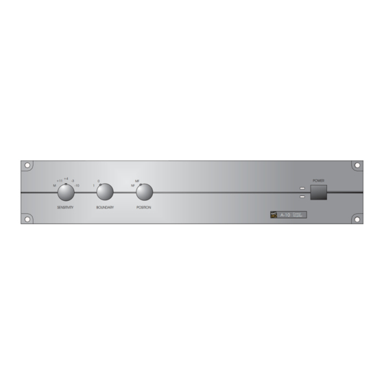
Figure 3a indicates proper wiring protocol for each type of connector. Since there are many different connector types and signal levels employed by source equipment, some experimentation may be necessary, keeping in mind that A-10 can accept a wide range of signals and has an input sensitivity control on the front panel. - Page 5 Fig.5 A-10 ControlAmplifier Front Panel POWER INDICATORS: Just to the left of the power switch on the A-10 Control Amplifier are two power related LED's. The upper (green) LED lights up indicating there is AC power to the amplifier and the POWER SWITCH is in the “on”position.
-
Page 6: Speaker Placement
However, a speaker’s upper frequency power response changes with distance, due to room influences and air absorption. The A-10 may be adjusted for flat response at two listening distances. The maximum highfrequency output is obtained with the control in the “FF” (far-field) position. In the near- field, the control attenuates 20 kHz by 2.5 dB, with no effect on frequencies below 3 kHz. -
Page 7: System Operation
SYSTEMOPERATION: The A-10 is capable of very high output levels, especially when listening in the near-field. Still, every speaker system has its limits. Protect your ears and use common sense. Harsh breakup at extremely high volume, or heat emanating from the drivers is an indication that the system has exceeded its output limits and you should lower the playback level. -
Page 8: System Specifications
SYSTEMSPECIFICATIONS: Type: Modular, two piece powered near/mid field monitor. Configuration: 2-way acoustic suspension. Woofer: 6.5" treated paper. Tweeter: 1" softdome. Magnetic Shielding: Full. PERFORMANCE SPECIFICATIONS: Amplifier Power: 150W (continuous RMS/ch), 300W (100ms peak). Peak Acoustic Output: 116 dB SPL (100ms pink noise @ 1M). Residual hum/noise: <10 dB SPL (A weighted @ 1M).
Need help?
Do you have a question about the A-10 and is the answer not in the manual?
Questions and answers