Table of Contents
Advertisement
www.nordictrack.com
Model No. NTEX04911.2
Serial No.
USER’'S MANUAL
Write the serial number in the space
above for reference.
Serial Number
Decal
ACTIVATE YOUR
WARRANTY
To register your product and
activate your warranty today, go
to www.nordictrackservice.com/
registration.
CUSTOMER CARE
For service at any time, go to
www.nordictrackservice.com.
Or call 1-800-TO-BE-FIT
(1-800-862-3348)
Mon.––Fri. 6 a.m.––6 p.m. MT
Sat. 8 a.m.––12 p.m. MT
Please do not contact the store.
CAUTION
Read all precautions and instruc-
tions in this manual before using
this equipment. Keep this manual
for future reference.
Advertisement
Table of Contents

Related Manuals for NordicTrack NTEX04911.2


Summary of Contents for NordicTrack NTEX04911.2
- Page 1 Model No. NTEX04911.2 Serial No. USER’’S MANUAL Write the serial number in the space above for reference. Serial Number Decal ACTIVATE YOUR WARRANTY To register your product and activate your warranty today, go to www.nordictrackservice.com/ registration. CUSTOMER CARE For service at any time, go to www.nordictrackservice.com.
-
Page 2: Table Of Contents
TABLE OF CONTENTS WARNING DECAL PLACEMENT ............. . . 2 IMPORTANT PRECAUTIONS . -
Page 3: Important Precautions
IMPORTANT PRECAUTIONS WARNING: To reduce the risk of serious injury, read all important precautions and instructions in this manual and all warnings on your exercise bike before using your exercise bike. ICON assumes no responsibility for personal injury or property damage sustained by or through the use of this product. - Page 5 STANDARD SERVICE PLANS...
-
Page 6: Before You Begin
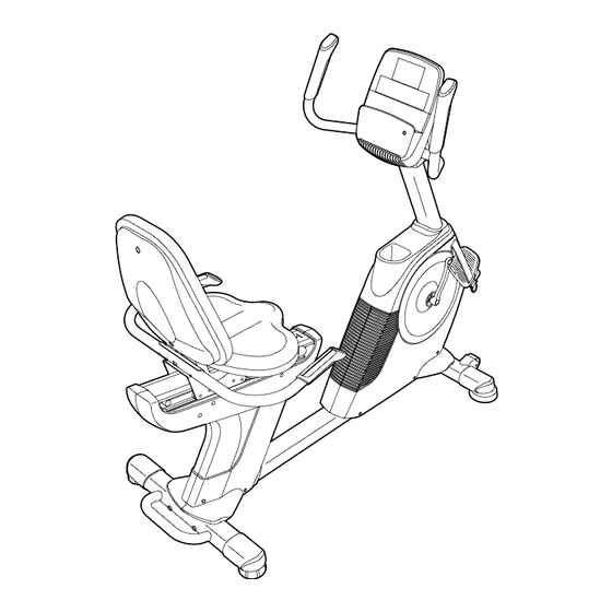
BEFORE YOU BEGIN Thank you for selecting the revolutionary reading this manual, please see the front cover of this NORDICTRACK GX 5.0 PRO exercise bike. The GX manual. To help us assist you, note the product model ® 5.0 PRO exercise bike provides an impressive selec- number and serial number before contacting us. -
Page 7: Part Identification Chart
PART IDENTIFICATION CHART Use the drawings below to identify the small parts needed for assembly. The number in parentheses below each drawing is the key number of the part, from the PART LIST near the end of this manual. The number following the key number is the quantity needed for assembly. -
Page 8: Assembly
ASSEMBLY •• Assembly requires two persons. •• In addition to the included tool(s), assembly requires the following tools: •• Place all parts in a cleared area and remove the one Phillips screwdriver packing materials. Do not dispose of the packing materials until you ... - Page 9 3. While a second person lifts the rear of the Frame (1), attach the Rear Stabilizer (16) to the Frame with two M10 x 105mm Screws (65). 4. Orient the Seat Frame (52) as shown. Attach the Seat Frame (52) to the Seat Carriage (41) with four M8 x 16mm Screws (69).
- Page 10 5. Tip: Avoid damaging the wires inside the Seat Handlebar (11) during this step. Attach the Seat Handlebar (11) to the Seat Frame (52) with two M8 x 65mm Bolts (70) and two M8 Locknuts (86). 6. Plug the Seat Pulse Wire (10) into the receptacle in the Right Rear Shield (79).
- Page 11 7. Attach the Seat (9) to the Seat Frame (52) with four M6 x 38mm Screws (25) and four M6 Washers (88). Note: Only two Screws and two Washers are shown. 8. Attach the Backrest (8) to the Seat Frame (52) with four M6 x 38mm Screws (25) and four M6 Washers (88).
- Page 12 9. Attach the Backrest Cover (36) to the Backrest (8) with two M6 x 18mm Screws (75). 10. Orient the Upright (2) and the Top Shield (44) as shown. Slide the Top Shield upward onto the Wire Ties Upright. Have a second person hold the Upright (2) and the Top Shield (44) near the Frame (1) until Wire step 11.
- Page 13 11. Tip: Avoid pinching the wires. Slide the Upright (2) onto the Frame (1). Avoid pinching the wires Attach the Upright (2) with four M10 x 16mm Screws (67) and four M10 Split Washers (54). Tip: Tighten the two Screws in the front of the Upright, and then tighten the other two Screws.
- Page 14 13. Identify and orient the Rear Upright Cover (57) as shown. Attach the Rear Upright Cover (57) to the Upright (2) with an M4 x 16mm Screw (77). 14. Untie and discard the wire ties on the Main Wire (43), the Frame Pulse Wire (42), and the Receiver Wire (40).
- Page 15 16. Identify the Right Pedal (21). Using an adjustable wrench, firmly tighten the Right Pedal (21) clockwise into the Right Crank Arm (23). Strap Post Firmly tighten the Left Pedal (not shown) counterclockwise into the Left Crank Arm (not shown). If necessary, press the right strap onto the post on the Right Pedal (21).
-
Page 16: The Chest Heart Rate Monitor
THE CHEST HEART RATE MONITOR HOW TO PUT ON THE HEART RATE MONITOR •• Do not expose the heart rate monitor to direct sun- light for extended periods of time; do not expose it to The heart rate temperatures above 122° F (50° C) or below 14° F monitor consists of (-10°... -
Page 17: How To Use The Exercise Bike
HOW TO USE THE EXERCISE BIKE HOW TO PLUG IN THE POWER ADAPTER HOW TO LEVEL THE EXERCISE BIKE IMPORTANT: If the exercise bike has been exposed If the exercise bike to cold temperatures, allow it to warm to room rocks slightly on temperature before plugging in the power adapter. - Page 18 CONSOLE DIAGRAM FEATURES OF THE CONSOLE The advanced console offers an array of features designed to make your workouts more effective and enjoyable. When you use the manual mode of the console, you can change the resistance of the pedals with the touch of a button.
- Page 19 HOW TO USE THE MANUAL MODE Distance (Dist.)——This display mode will show the distance that you have pedaled in miles or 1. Begin pedaling or press any button on the kilometers. console to turn on the console. Pulse——This display mode will show your heart rate When you turn on the console, the display will turn when you use the handgrip heart rate monitor or on.
-
Page 20: To Use The Sound System
Press the Home button to return to the default If the display does not show your heart rate, make menu (see HOW TO CHANGE CONSOLE sure that your hands are positioned as described. SETTINGS on page 23 to set the default menu). Be careful not to move your hands excessively or If necessary, press the Home button again. - Page 21 HOW TO USE AN ONBOARD WORKOUT the next segment, the resistance level and/or target speed will appear in the display for a few seconds 1. Begin pedaling or press any button on the to alert you. The resistance of the pedals will then console to turn on the console.
-
Page 22: To Use An Ifit Workout
HOW TO USE AN IFIT WORKOUT When you select an iFit workout, the display will show the duration of the workout and the approxi- You must have an iFit module to use an iFit workout. mate number of calories you will burn. The display To purchase an iFit module at any time, go to may also show the name of the workout. - Page 23 HOW TO CHANGE CONSOLE SETTINGS Units——The currently selected unit of measurement will appear in the display. To change the unit of 1. Select the settings mode. measurement, press the Enter button repeatedly. To view distance in miles, select ENGLISH. To view To select the settings mode, press and hold down distance in kilometers, select METRIC.
-
Page 24: Fcc Information
FCC INFORMATION This equipment has been tested and found to comply with the limits for a Class B digital device, pursuant to part 15 of the FCC Rules. These limits are designed to provide reasonable protection against harmful interference in a residential installation. This equipment generates, uses, and can radiate radio frequency energy and, if not installed and used in accordance with the instructions, may cause harmful interference to radio communications. -
Page 25: Maintenance And Troubleshooting
MAINTENANCE AND TROUBLESHOOTING Inspect and tighten all parts of the exercise bike Locate the Reed Switch (46). Rotate the Pulley (29) regularly. Replace any worn parts immediately. until a Pulley Magnet (30) is aligned with the Reed Switch. Loosen, but do not remove, the indicated M4 To clean the exercise bike, use a damp cloth and a x 16mm Screw (77). - Page 26 HOW TO ADJUST THE DRIVE BELT Loosen the M6 x 20mm Hex Screw (84). Tighten the M10 x 50mm Hex Screw (83) until the Drive Belt (47) If the pedals slip while you are pedaling, even while the is tight. When the Drive Belt is tight, tighten the M6 x resistance is adjusted to the highest setting, the drive 20mm Hex Screw.
-
Page 27: Exercise Guidelines
EXERCISE GUIDELINES Burning Fat——To burn fat effectively, you must exer- WARNING: cise at a low intensity level for a sustained period of Before beginning this time. During the first few minutes of exercise, your or any exercise program, consult your physi- body uses carbohydrate calories for energy. - Page 28 SUGGESTED STRETCHES The correct form for several basic stretches is shown at the right. Move slowly as you stretch; never bounce. 1. Toe Touch Stretch Stand with your knees bent slightly and slowly bend forward from your hips. Allow your back and shoulders to relax as you reach down toward your toes as far as possible.
-
Page 29: Part List
PART LIST Model No. NTEX04911.2 R0913A Key No. Qty. Description Key No. Qty. Description Frame Rear Stabilizer Cover Upright Handlebar Grip Front Stabilizer Cover Flange Screw Console Power Adapter Rail Seat Frame Adjustment Bar M10 Locknut Left Handlebar M10 Split Washer... -
Page 30: Exploded Drawing
EXPLODED DRAWING A Model No. NTEX04911.2 R0913A... - Page 31 EXPLODED DRAWING B Model No. NTEX04911.2 R0913A...
-
Page 32: Ordering Replacement Parts
ORDERING REPLACEMENT PARTS To order replacement parts, please see the front cover of this manual. To help us assist you, be prepared to provide the following information when contacting us: •• the model number and serial number of the product (see the front cover of this manual) ••...
Need help?
Do you have a question about the NTEX04911.2 and is the answer not in the manual?
Questions and answers