NordicTrack GX2.0 User Manual
Ntex029100
Hide thumbs
Also See for GX2.0:
- User manual (28 pages) ,
- Manual (24 pages) ,
- Manual del usuario (24 pages)
Table of Contents
Advertisement
www.nordictrack.com
Model No. NTEX02910.0
Serial No.
Write the serial number in the
space above for reference.
Serial Number Decal
(under frame)
QUESTIONS?
If you have questions, or if parts are
damaged or missing, DO NOT
CONTACT THE STORE; please
contact
Customer
Care.
iMPORTANT: Please register this
product
(see the limited warranty
on the back cover of this manual)
before contacting
Customer
Care.
CALL TOLL-FREE:
1-888-825-2588
Mon.-Fri.,
6 a.m.-6 p.m. MT
Sat. 8 a.m.-4 p.m. MT
ON THE WEB:
www.nordictrackservice.com
US
AL
Advertisement
Table of Contents

Related Manuals for NordicTrack GX2.0


Summary of Contents for NordicTrack GX2.0
- Page 1 Model No. NTEX02910.0 Serial No. Write the serial number in the space above for reference. Serial Number Decal (under frame) QUESTIONS? If you have questions, or if parts are damaged or missing, DO NOT CONTACT THE STORE; please contact Customer Care.
- Page 2 , Do not allow children on or around machine. • User weight must not exceed 275 pounds. • Replace label if illegible, or damaged, removed. NordicTrack is a registered trademark of ICON IP, Inc.
- Page 3 iMPORTANT PRECAUTIONS WARNING: To reduce the risk ofserious njury, read a . mportant precautions instructions in this manual and all warnings on your exercise bike before using your exercise bike. ICON assumes no responsibility for personal injury or property damage sustained by or through use of this product.
-
Page 4: Overview
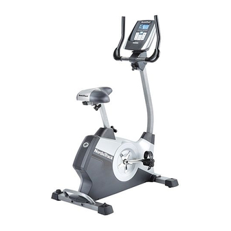
BEFORE YOU BEGIN Thank you for selecting the revolutionary NordicTrack ® after reading this manual, please see the front cover GX 2.0 exercise bike. Cycling is an effective exercise of this manual. To help us assist you, note the product... -
Page 5: Assembly
ASSEMBLY To hire an authorized service technician to assemble the exercise bike, call 1-800-445-2480. Assembly requires two persons. Place all parts of the exercise bike in a cleared area and remove the packing materials. Do not dispose of the packing materials until assembly is completed. in addition to the included tool(s), assembly... - Page 6 Attach the Rear Stabilizer (3) to the Frame (1) with two M10 x 95mm Patch Screws (76). Attach the Front Stabilizer (2) to the Frame (1) with two M10 x 95mm Patch Screws (76). Loosen the Adjustment Knob (27)in the Frame (1) a few turns.
- Page 7 Orient the Seat (23) and the Seat Carriage (24) as shown. Attach the Seat (23) to the Seat Carriage (24) with four M8 Locknuts (72) and four M8 Split Washers (75). Slide the Seat Carriage (24) onto the Seat Post (6).
- Page 8 While another person holds the Console (13) near the Handlebar (5), connect the console Avoid pinching wires to the Extension Wire (59) and the Pulse the wires Wire (61). Insert the excess wire downward into the Handlebar (5) or upward into the Console (13). Tip: Avoid pinching the wires.
- Page 9 Slide the Front Shield Cover (7) upward onto the Upright (4). While another person holds the Upright (4) near the Frame (1), connect the Extension Wire (59) to the Main Wire (58). Insert the Upright (4) into the Frame (1). Avoid pinching Tip: Avoid pinching the wires.
- Page 10 10. Plug the Power Adapter (67) into the receptacle on the frame of the exercise bike. To plug the Power Adapter (67) into an outlet, see HOW TO PLUG IN THE POWER ADAPTER on page 11. 11. Make sure that all parts are properly tightened before you use the exercise bike.
- Page 11 HOW TO USE THE EXERCISE BiKE HOW TO PLUG IN THE POWER ADAPTER HOW TO ADJUST THE HEIGHT OF THE SEAT IMPORTANT: If the exercise bike has been For effective exercise, the seat should be at the exposed to cold temperatures, allow it to warm to proper height.
- Page 12 HOW TO ADJUST THE ANGLE OF THE HOW TO ADJUST THE PEDAL STRAPS HANDLEBAR To adjust the To adjust the angle of the handlebar, first loosen the pedal straps, first adjustment knob a few turns. Next, pull the knob out- pull the ends of ward, pivot the handlebar to the desired angle, and the straps off the...
- Page 13 CONSOLE DIAGRAM STRRT MENU V ]I ENTER DISPLAY 4" HILL CLIMBING RESISTANCE WORKOUTS VOLUME INTERVAL WORKOUTS FEATURES OF THE CONSOLE With the iFit Live mode, you can download personal- ized workouts, create your own workouts, track your The advanced console offers an array of features workout results, and access many other features.
- Page 14 HOW TO ACTIVATE THE CONSOLE Change the resistance of the pedals as desired. The included power adapter can be used to operate the exercise bike. See HOW TO PLUG IN THE As you pedal, change the resistance of the pedals POWER ADAPTER on page 11.
- Page 15 HOW TO USE A PRESET WORKOUT Time--When the manual mode is selected, this display mode will show the elapsed time. When a workout is selected, this display mode will show Begin pedaling or press any button on the console to turn on the console. the time remaining in the workout instead of the elapsed time.
- Page 16 Begin pedaling to start the workout. iMPORTANT: The target speed is intended only to provide motivation. Your actual pedaling Each workout is divided into one-minute seg- pace may be slower than the target speed. ments. One resistance level and one target speed Make sure to pedal at a pace that is comfort- are programmed for each segment.
- Page 17 HOW TO USE THE IFIT TRAINING MODE HOW TO USE THE iNFORMATiON MODE The console features an information mode that allows The optional iFit Live module allows your console to communicate with your wireless network and unlocks you to view usage information for the exercise bike, select a unit of measurement for the console, and exciting new features.
- Page 18 Check the status of the iFit Live module if Adjust the contrast level of the display if desired. desired. The currently selected contrast level will also To check the status of the iFit Live module, press the Increase and Decrease buttons until the bullet appear in the display.
- Page 19 MAINTENANCE AND TROUBLESHOOTING Inspect and tighten all parts of the exercise bike regu- Next, rotate the Left Crank Arm larly. Replace any worn parts immediately. (20) to a vertical To clean the exercise bike, use a damp cloth and a position with the end of the Left small amount of mild soap.
-
Page 20: How To Adjust Drive Belt
HOW TO ADJUST THE DRIVE BELT Next, rotate the Right Crank Arm (19) to a vertical position with the end of the Right Crank Arm pointing If you can feel the pedals slip while you are pedaling, upward. even when the resistance is adjusted to the highest level, the drive belt may need to be adjusted. - Page 21 EXERCISE GUiDELiNES Burning Fat--To burn fat effectively, you must exer- ,& WARNING: Before this beginning cise at a low intensity level for a sustained period of time. During the first few minutes of exercise, your or any exercise program, consult your physi- body uses carbohydrate calories for energy.
- Page 22 PART LISTm Model No. NTEX02910.0 R0710A Key No. Qty. Description Key No. Qty. Description Frame M6 x 70mm Bolt Set Front Stabilizer M6 x 60mm Bolt Set Rear Stabilizer Arm Lock Upright C-magnet Handlebar Drive Belt Seat Post Magnet Front Shield Cover Clamp Reed Switch/Wire Top Shield Cover...
- Page 23 EXPLODED DRAWING m Model No. NTEX02910.0 Ro71oA 85 72...
- Page 24 ORDERING REPLACEMENT PARTS To order replacement parts, please see the front cover of this manual. To help us assist you, be prepared to provide the following information when contacting us: o the model number and serial number of the product (see the front cover of this manual) o the name of the product (see the front cover of this manual) o the key number and description of the replacement part(s) (see the PART LIST and the EXPLODED DRAWING near the end of this manual)
Need help?
Do you have a question about the GX2.0 and is the answer not in the manual?
Questions and answers