Table of Contents
Advertisement
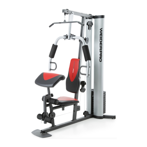
Model No. 831.14922.2
Serial No.
Write the serial number in the space
WEIGHT SYSTEM EXERCISER
above for reference.
User’'s Manual
Serial Number Decal
(under the seat)
•• Assembly
•• Operation
•• Maintenance
•• Part List and Drawing
Sears, Roebuck and Co.
Hoffman Estates, IL 60179
CAUTION
Read all precautions and instruc-
tions in this manual before using
this equipment. Keep this manual
for future reference.
Advertisement
Table of Contents

Subscribe to Our Youtube Channel
Related Manuals for WeiderPro 831.14922.2


Summary of Contents for WeiderPro 831.14922.2
- Page 1 Model No. 831.14922.2 Serial No. Write the serial number in the space WEIGHT SYSTEM EXERCISER above for reference. User’’s Manual Serial Number Decal (under the seat) •• Assembly •• Operation •• Maintenance •• Part List and Drawing Sears, Roebuck and Co.
-
Page 2: Table Of Contents
TABLE OF CONTENTS WARNING DECAL PLACEMENT ............. . . 2 IMPORTANT PRECAUTIONS . -
Page 3: Important Precautions
IMPORTANT PRECAUTIONS WARNING: To reduce the risk of serious injury, read all important precautions and instructions in this manual and all warnings on your weight system before using your weight system. ICON assumes no responsibility for personal injury or property damage sustained by or through the use of this product. -
Page 4: Before You Begin
BEFORE YOU BEGIN Thank you for selecting the versatile WEIDER PRO ® reading this manual, please see the front cover of this 6900 weight system. The weight system offers a selec- manual. To help us assist you, note the product model tion of weight stations designed to develop every major number and serial number before contacting us. -
Page 5: Part Identification Chart
PART IDENTIFICATION CHART Refer to the drawings below to identify small parts used in assembly. The number in parentheses by each drawing is the key number of the part, from the PART LIST near the end of this manual. IMPORTANT: If you cannot find a part in the hardware kit, check to see if it has been preassembled. -
Page 6: Assembly
ASSEMBLY •• Assembly requires two persons. •• The following tool(s) (not included) may be required for assembly: •• Because of its weight and size, assemble the two adjustable wrenches weight system in the location where it will be used. Make sure that there is enough clearance one rubber mallet to walk around the weight system. -
Page 7: Frame Assembly
Frame Assembly 2. Attach the Foot Plate (38) to the Base (1) with an M10 x 130mm Bolt (72) and an M10 Locknut (56). Do not overtighten the Locknut; the Foot Plate must pivot easily. 3. Attach the Weight Guides (21) and the Base (1) to the Stabilizer (2) with two M10 x 67mm Bolts (71), two M10 Washers (57), and two M10 Locknuts (56). - Page 8 4. Attach the Upright (3) to the Base (1) with two M8 x 63mm Carriage Bolts (87) and two M8 Locknuts (58). Do not tighten the Locknuts yet. 5. Attach the Front Leg (7) to the Base (1) with two M8 x 63mm Carriage Bolts (87) and two M8 Locknuts (58).
- Page 9 6. Attach the Seat Tube (6) to the Upright (3) with two M8 x 65mm Bolts (68), two M8 Washers (59), and two M8 Locknuts (58). Do not tighten the Locknuts yet. Attach the Seat Tube (6) to the Front Leg (7) in the same way.
- Page 10 8. Attach the Top Frame (4) to the Upright (3) with two M10 x 67mm Bolts (71), two M10 Washers (57), and two M10 Locknuts (56). Do not tighten the Locknuts yet. Attach the Top Frame (4) to the Weight Guides (21) with two M10 x 25mm Screws (74).
-
Page 11: Button
11. Apply grease to an M10 x 77mm Bolt (79). Attach the Pivot Frame (5) to the Top Frame (4) with the M10 x 77mm Bolt (79) and an M10 Locknut (56). Do not overtighten the Locknut; the Pivot Frame must pivot easily. Grease Arm Assembly 12. -
Page 12: Shoulder
14. Apply grease to an M10 x 86mm Carriage Bolt (67) and to two Arm Bushings (44). Attach the Left Arm (10) to the Pivot Frame (5) with the M10 x 86mm Carriage Bolt (67), a Carriage Bolt Bushing (20), the two Arm Bushings (44), an M10 Washer (57), and an M10 Locknut (56). - Page 13 16. Identify the two V-pulleys (46), the nine Thick Pulleys (not shown), and the two Thin Pulleys (not shown). Tip: It may be helpful to refer to the EXPLODED DRAWING near the end of this manual to identify the pulleys. Route the Arm Cable (54) over a V-pulley (46).
- Page 14 19. Apply grease to an M8 x 22mm Shoulder Bolt (65). Attach the Arm Cable (54) to the right Cable Grease Pivot (39) with the M8 x 22mm Shoulder Bolt 54 39 (65) and an M8 Locknut (58). 20. See the CABLE DIAGRAM. Identify the Low Cable (53).
- Page 15 22. Route the Low Cable (53) through the Upright (3) and under a Thick Pulley (48). Attach the Thick Pulley (48) inside the Upright (3) with an M10 x 46mm Bolt (81) and an M10 Locknut (56). 23. Route the Low Cable (53) over a Thick Pulley (48).
- Page 16 25. Attach the Low Cable (53) to the U-bracket (45) with an M8 Washer (59) and an M8 Locknut (58). See the inset drawing. Do not overtighten the M8 Locknut (58); it should be threaded onto the end of the Low Cable (53) so that only two threads are showing above the Locknut.
- Page 17 28. Wrap the High Cable (55) under a Thick Pulley (48). Attach the Thick Pulley (48), a Small Cable Trap (51), and two Half Guards (43) to the upper hole in the U-bracket (45) with an M10 x 51mm Bolt (66) and an M10 Locknut (56).
-
Page 18: Seat Assembly
31. Thread an M12 Nut (84) all the way onto the High Cable (55). Place a Large Washer (85) on top of the Weight Selector (24). Tighten the High Cable (55) into the Weight Selector (24) until all the slack is removed from the cables. -
Page 19: M4.2 X 16Mm Self-Tapping
34. Insert the Pad Tube (29) into the Front Leg (7). Slide a Small Foam Pad (28) onto each side of the Pad Tube (29). Then, press a Pad Cap (34) into each Small Foam Pad. Slide a Small Foam Pad (28) onto each end of the Leg Lever (8). - Page 20 36. Attach a Shroud Support (19) and the bottom of the Left Shroud (17) to the Base (1) and the Stabilizer (2) with four M4.2 x 16mm Self-tapping Screws (49) and four M4 Washers (33). Do not tighten the Screws yet. Repeat steps 35 and 36 to attach the Right Shroud (not shown).
-
Page 21: Adjustment
ADJUSTMENT This section explains how to adjust the weight system. See the EXERCISE GUIDELINES on page 27 for impor- tant information about how to get the most benefit from your exercise program. Also, refer to the accompanying exercise guide to see the correct form for several exercises. Make sure that all parts are properly tightened each time the weight system is used. - Page 22 CONVERTING THE ARMS To use the Arms (9, 10) as butterfly arms, insert the Arm Pins (40) into the holes in the Upright (3) as shown. To use the Arms (9, 10) as press arms, insert the Arm Pins (40) into the holes in the Pivot Frame (5) and the Arms.
-
Page 23: Weight Resistance Chart
LOCKING THE WEIGHT STACK To lock the weight stack after each workout, insert the Lock Pin (89) through one of the Weight Guides (21), and secure the Lock (88) on the Lock Pin. WEIGHT RESISTANCE CHART The chart below shows the approximate weight resistance at each exercise station. The numbers in the left col- umn refer to the 12.5-lb. -
Page 24: Maintenance
MAINTENANCE Make sure that all parts are properly tightened each time the weight system is used. Replace any worn parts immediately. To clean the weight system, use a damp cloth and a mild, non-abrasive detergent; do not use sol- vents to clean the weight system. TIGHTENING THE CABLES Woven cable, the type of cable used on the weight system, can stretch slightly when it is first used. -
Page 25: Cable Diagram
CABLE DIAGRAM The diagram below shows the proper routing of the cables. The numbers in each drawing show the proper route of that cable. Cut along the dotted line, and refer to this diagram while you assemble the cables and the pulleys. If the cables and the pulleys are not assembled correctly, the weight system will not function properly and damage may occur. - Page 26 NOTES...
-
Page 27: Exercise Guidelines
EXERCISE GUIDELINES FOUR TYPES OF STRENGTH WORKOUTS workout, and the numbers of repetitions and sets to complete. Progress at your own pace and be sensitive Note: A ““repetition”” is one complete cycle of an to your body’’s signals. Follow each workout with at exercise, such as one sit-up. - Page 28 EXERCISE LOG Make copies of this page, and use the copies to schedule and record your strength and aerobic workouts. Scheduling and recording your workouts will help you to make exercise a regular and enjoyable part of your life. Strength Exercise Lbs.
-
Page 29: Part List
PART LIST Model No. 831.14922.2 R0513A Key No. Qty. Description Key No. Qty. Description Base Small Cable Trap Stabilizer 13mm Spacer Upright Low Cable Top Frame Arm Cable Pivot Frame High Cable Seat Tube M10 Locknut Front Leg M10 Washer... -
Page 30: Exploded Drawing
EXPLODED DRAWING A Model No. 831.14922.2 R0513A 65 54... - Page 31 EXPLODED DRAWING B Model No. 831.14922.2 R0513A 50 41...
-
Page 32: 90 Day Full Warranty
90 DAY FULL WARRANTY If this Sears Weight System Exerciser fails due to a defect in material or workmanship within 90 days of the date of purchase, call 1-800-4-MY-HOME® (1-800-469-4663) to arrange for free repair (or replace- ment if repair proves impossible). This warranty does not apply when the Weight System Exerciser is used commercially or for rental pur- poses.
Need help?
Do you have a question about the 831.14922.2 and is the answer not in the manual?
Questions and answers