
Related Manuals for D-Link DP-301P


Summary of Contents for D-Link DP-301P
-
Page 1: Print Server
Model DP-301P Multiprotocol Ethernet/Fast Ethernet Print Server Hardware Guide Rev. 01 (March 1999) 6DP301P...01 Printed In Taiwan RECYCLABLE... -
Page 2: Limited Warranty
Registration Card is filled out and returned to a D-Link office within ninety (90) days of purchase. A list of D-Link offices is provided at the back of this manual, together with a copy of the Registration Card. Failing such timely registration of purchase, the warranty period shall be limited to 90 days. - Page 3 Registration Card. If a Registration Card for the product in question has not been returned to a D-Link office, then a proof of purchase (such as a copy of the dated purchase invoice) must be provided when requesting warranty service. The term "purchase" in this software warranty refers to the purchase transaction and resulting licence to use such software.
- Page 4 ACCIDENT, FIRE, LIGHTNING OR OTHER HAZARD. LIMITATION OF LIABILITY IN NO EVENT WILL D-LINK BE LIABLE FOR ANY DAMAGES, INCLUDING LOSS OF DATA, LOSS OF PROFITS, COST OF COVER OR OTHER INCIDENTAL, CONSEQUENTIAL OR INDIRECT DAMAGES ARISING OUT THE INSTALLATION, MAINTENANCE, USE, PERFORMANCE, FAILURE OR INTERRUPTION OF A D- LINK PRODUCT, HOWEVER CAUSED AND ON ANY THEORY OF LIABILITY.
- Page 5 Wichtige Sicherheitshinweise Bitte lesen Sie sich diese Hinweise sorgfältig durch. Heben Sie diese Anleitung fü r den spätern Gebrauch auf. Vor jedem Reinigen ist das Gerät vom Stromnetz zu trennen. Vervenden Sie keine Flü ssig- oder Aerosolreiniger. Am besten dient ein angefeuchtetes Tuch zur Reinigung. Um eine Beschädigung des Gerätes zu vermeiden sollten Sie nur Zubehörteile verwenden, die vom Hersteller zugelassen sind.
- Page 6 Trademarks Copyright 1997 D-Link Corporation. Contents subject to change without prior notice. D-Link is a registered trademark of D-Link Corporation/D-Link Systems, Inc. All other trademarks belong to their respective proprietors. Copyright Statement No part of this publication may be reproduced in any form or by...
-
Page 7: Table Of Contents
XTERNAL EATURES Front ......................5 Back ......................6 UNPACKING AND INSTALLATION............. 8 ............... 8 NPACKING AND NSPECTION DP-301P ................9 NSTALLING THE ................10 OWER UP AND TEST Indicator Test ..................10 Circuit Tests .................... 10 Operational Test ..................11 PRODUCT SPECIFICATIONS.............. -
Page 8: About This Guide
The software and related documentation included with your DP-301P are important parts of the DP-301P package. For information on installing and using the included software, see the PS Admin User’ s Guide. -
Page 9: Introduction
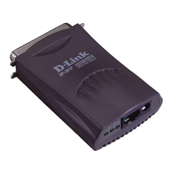
DP-301P Print Server Hardware Guide NTRODUCTION The DP-301P is a pocket-sized device for connecting a printer directly to an Ethernet or Fast Ethernet local-area network (LAN). The DP-301P will manage the flow of data from networked computers to the connected printer, delivering jobs to the printer much faster than a computer acting as a file server or print server can. -
Page 10: External Features
DP-301P, and all console messages and management report information will be returned, via Telnet. External Features This section describes the visible parts of the DP-301P print server. Introduction... -
Page 11: Front
Input DP-301P Front Section Network Port The network port, an RJ-45 jack in the middle of the DP-301P’ s front section, provides for connection to the network through an appropriate twisted-pair cable (Category 3 or higher for 10Base-T Ethernet, Category 5 or higher for 100Base-TX Fast Ethernet). -
Page 12: Back
This indicator blinks (goes off briefly) when the DP-301P is receiving from the network. This indicator shows steady green whenever the DP-301P is transferring print data through its printer port. Back The “back” section of the DP-301P consists entirely of the device’ s printer port. DP-301P Back End Introduction... -
Page 13: Printer Port
DP-301P Print Server Hardware Guide Printer Port The printer port can be configured using the PS Admin program, or by commands issued to the DP-301P via Telnet. See the PS Admin User’ s Guide for configuration procedures. Introduction... -
Page 14: Unpacking And Installation
NPACKING AND NSTALLATION This chapter explains how to install your DP-301P print server and connect it to the network. It also describes the automatic power-on self-test. Unpacking and Inspection Carefully remove all items from the package. In addition to this... -
Page 15: Installing The Dp-301P
6. Switch printer power on. 7. Plug the AC power adapter’ s output plug into the DP-301P’ s DC power input jack. 8. Plug the AC power adapter into an AC power outlet. This will supply power to the DP-301P. -
Page 16: Power-Up And Self-Test
LED indicators. The second procedure comprises programmed tests of the DP-301P’ s internal circuitry. If any fault is found during the circuitry tests, testing stops and a continuous pattern of flashes signals the nature of the fault. -
Page 17: Operational Test
PS Admin software and completed the PS Admin procedures for configuring the DP-301P. See the instructions given in the PS Admin User’ s Guide ("Getting Started Setting up Your Print Server"... -
Page 18: Product Specifications
DP-301P Print Server Hardware Guide RODUCT PECIFICATIONS Printer Connection Printer Port: IEEE 1284 standard bidirectional parallel interface with 36-pin connector. Bidirectional Communication: Hewlett-Packard PJL (Printer Job Language) standard for bidirectional communication. Network Connection Network Standards: IEEE 802.3 10Base-T Ethernet and IEEE 802.3u 100Base-TX Fast Ethernet. - Page 19 DP-301P Print Server Hardware Guide TCP/IP Protocols Supported: BOOTP, SNMP, Telnet, TFTP, FTP, lpd, RARP, DHCP Management and Diagnostics Standard: SNMP MIBs: MIB-II (RFC 1213) Diagnostic LED Indicators: Pw/Tx, Lk/Rx, LPT Environmental and Physical Power Supply: External AC power adapter providing 5V/1.5A DC power Dimensions: 92.8mm...
-
Page 20: Port Pinouts
INOUTS The following table lists the pinouts of the DP-301P’ s 36-pin parallel port connector (identical to the parallel port connector used on most printers.) Signal names beginning with n are active-low signals. Pin # Signal Source nStrobe Data 1... - Page 21 DP-301P Print Server Hardware Guide Peripheral Logic High Signal Ground (nStrobe) Signal Ground (Data 1) Signal Ground (Data 2) Signal Ground (Data 3) Signal Ground (Data 4) Signal Ground (Data 5) Signal Ground (Data 6) Signal Ground (Data 7) Signal Ground (Data 8)
-
Page 23: Index
NDEX 100Base-TX, 5, 12 MIB, 13 10Base-T, 5, 12 NetBEUI, 4, 12 AC power adapter, 5, 8, 9, 13 NetWare, 4 AppleTalk, 4, 12 network port, 5, 12 automatic self test, 8 power adapter, 5, 8, 9, 13 bidirectional printer port, 3, 12 power-up sequence, 9 cable, 5 print test, 11... - Page 24 World Trade Center P. O. Box 70396, 107 24 Stockholm Sweden TEL: 46-8-700-6211 FAX: 46-8-219-640 E-MAIL: info@dlink.se U.K. D-LINK (EUROPE) LTD. D-Link House, 6 Garland Road, Stanmore, London HA7 1DP U.K. TEL: 44-181-235-5555 FAX: 44-181-235-5500 WEB: www.dlink.com.uk BBS: 44-181-235-5511 E-MAIL: info@dlink.co.uk AUSTRALIA D-LINK AUSTRALIA PTY.LTD.
- Page 25 8. What category best describes your company? oAerospace oEngineering oEducation oFinance oHospital oLegal oInsurance/Real Estate oManufacturing oRetail/Chainstore/Wholesale oGovernment oTransportation/Utilities/Communication oVAR oSystem house/company oOther________________________________ 9. Would you recommend your D-Link product to a friend? oYes oNo oDon't know yet 10.Your comments on this product? __________________________________________________________________________________________...
Need help?
Do you have a question about the DP-301P and is the answer not in the manual?
Questions and answers