
Related Manuals for Firepower Firepower FP-55


Summary of Contents for Firepower Firepower FP-55
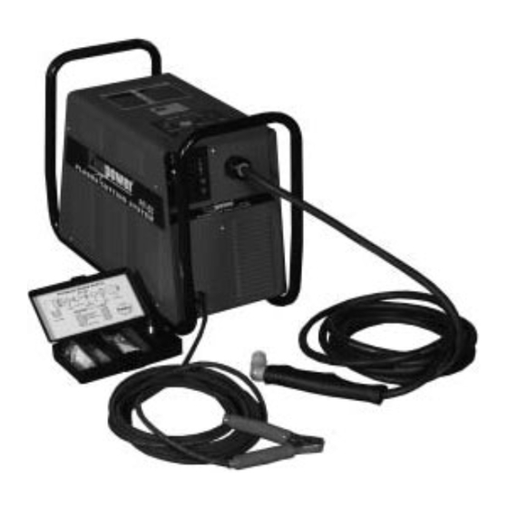
- Page 1 Plasma Cutting Power Supply Firepower FP-55 A-02766 Operating Manual April 4, 2003 Manual No. 0-2846...
- Page 3 While the information contained in this Manual represents the Manufacturer's best judgement, the Manufacturer assumes no liability for its use. Plasma Cutting Power Supply Firepower 55 (FP-55) Operating Manual Number 0-2846 www.firepoweronline.com Published by: Thermal Dynamics Corporation...
-
Page 4: Table Of Contents
TABLE OF CONTENTS SECTION 1: GENERAL INFORMATION ....................1-1 1.01 Notes, Cautions and Warnings ..............1-1 1.02 Important Safety Precautions ............... 1-1 1.03 Publications ....................1-2 1.04 Note, Attention et Avertissement ..............1-3 1.05 Precautions De Securite Importantes ............1-3 1.06 Documents De Reference ................ - Page 5 TABLE OF CONTENTS (continued) SECTION 5: CUSTOMER/OPERATOR SERVICE ................. 5-1 5.01 Introduction ....................5-1 5.02 General Maintenance ................... 5-1 5.03 Common Faults .................... 5-2 5.04 Basic Troubleshooting Guide ................ 5-3 5.05 Power Supply Basic Parts Replacement ............5-5 SECTION 6: PARTS LISTS ........................
-
Page 7: General Information
SECTION 1: GASES AND FUMES GENERAL INFORMATION Gases and fumes produced during the plasma cutting process can be dangerous and hazardous to your health. 1.01 Notes, Cautions and Warnings • Keep all fumes and gases from the breathing area. Throughout this manual, notes, cautions, and warnings Keep your head out of the welding fume plume. -
Page 8: Publications
• Wear dry gloves and clothing. Insulate yourself from the work piece or other parts of the welding PLASMA ARC RAYS circuit. • Repair or replace all worn or damaged parts. Plasma Arc Rays can injure your eyes and burn your skin. •... -
Page 9: Note, Attention Et Avertissement
5. ANSI Standard Z41.1, STANDARD FOR MEN’S 1.04 Note, Attention et SAFETY-TOE FOOTWEAR, obtainable from the Avertissement American National Standards Institute, 1430 Broadway, New York, NY 10018 Dans ce manuel, les mots “note,” “attention,” et 6. ANSI Standard Z49.2, FIRE PREVENTION IN “avertissement”... - Page 10 les avertissements, toutes les précautions de sécurité et toutes les consignes avant d’utiliser le matériel. CHOC ELECTRIQUE Composez le + 603-298-5711 ou votre distributeur local si vous avez des questions. Les chocs électriques peuvent blesser ou même tuer. Le procédé au jet de plasma requiert et produit de l’énergie électrique haute tension.
-
Page 11: Documents De Reference
• Pour des renseignements sur la manière de tester le bruit, consultez l’article 1, page 5. RAYONS D’ARC DE PLASMA 1.06 Documents De Reference Les rayons provenant de l’arc de plasma peuvent blesser vos yeux et brûler votre peau. Le procédé à l’arc de plasma Consultez les normes suivantes ou les révisions les plus produit une lumière infra-rouge et des rayons ultra-vio- récentes ayant été... - Page 12 9. Norme 70 de la NFPA, CODE ELECTRIQUE NATIONAL, disponible auprès de la National Fire Protection Association, Batterymarch Park, Quincy, MA 02269 10. Norme 51B de la NFPA, LES PROCÉDÉS DE COUPE ET DE SOUDAGE, disponible auprès de la National Fire Protection Association, Batterymarch Park, Quincy, MA 02269 11.
-
Page 13: Declaration Of Conformity
1.07 Declaration of Conformity Manufacturer: Thermal Dynamics Corporation Address: Industrial Park #2 West Lebanon, New Hampshire 03784 The equipment described in this manual conforms to all applicable aspects and regulations of the ‘Low Voltage Direc- tive’ (European Council Directive 73/23/EEC as amended by Council Directive 93/68/EEC) and to the National legislation for the enforcement of this Directive. -
Page 14: Statement Of Warranty
THIS WARRANTY IS INVALID IF THE PRODUCT IS SOLD BY NON-AUTHORIZED PERSONS. The limited warranty periods for Firepower products shall be as follows: A maximum of four (4) years from date of sale to an authorized distributor and a maximum of three (3) years from date of sale by such distributor to the Purchaser, and with the following further limitations on such three (3) year period. -
Page 15: Introduction
1. Front Panel Features This manual contains descriptions, operating instructions • Main power ON/OFF switch and basic maintenance procedures for the Firepower FP-55 Plasma Cutting Power Supply only. Servicing of • RUN/SET switch this equipment is restricted to properly trained person- •... -
Page 16: Power Supply Options
8. Weight 52 lbs (23.6 kg) Weight includes Power Supply w/Input Cable and plug, Work Lead, and Torch & Leads. 9. Overall Dimensions (incl. handles) Length: 22-1/2 inches (572 mm) Width: 10-3/4 inches (273 mm) Height: 16-3/8 inches (416 mm) B. -
Page 17: Introduction
SECTION 3: CAUTION INSTALLATION Operation without proper air flow will inhibit proper cooling and reduce duty cycle. 3.01 Introduction 3.03 Unpacking NOTES The product is packaged and protected to prevent dam- Depending on how the system was ordered, some age during shipping. Power Supply Options may already be installed. -
Page 18: Primary Input Power Connections
Connect the gas supply as follows: 3.05 Primary Input Power Connections 1. If an optional air line filter is to be installed, refer to proce- dures in subsection 3.06-D. This power supply comes with a factory-installed input 2. Connect the gas line to the inlet port. The illustration shows power cable and plug designed to accept input power of typical fittings as an example. - Page 19 D. Installing Optional Single-Stage Air Filter Additional filtering is recommended when using air from a compressor to insure that moisture and debris from the supply hose does not enter the torch. Although the Pres- Regulator/Filter Inlet Port sure Regulator does have its own filter, the optional Assembly Single-Stage Air Filter is recommended for improved fil- tering.
-
Page 20: Torch Connections
3.07 Torch Connections Note: Actual Bulkhead NOTE Adapter configuration may Pilot Lead Stud Connector differ from that shown. Equipment ordered as a system will have the Torch factory connected to the Power Supply. Adapter Plug The Torch Leads must be properly installed to the Power Control Circuit Supply for proper operation. -
Page 21: Ground Connections For Mechanized Applications
2. Components that are mounted on the cutting machine; CNC controller, plasma remote controls, height con- Adapter Connector Negative/Plasma trollers, remote arc starters, etc., should be grounded Lead Connection to the cutting machine frame (chassis) with at least a Adapter 12 AWG (4 mm ) wire. - Page 22 welded end to end for greater lengths. Locate the rod D. Routing Of Torch Leads as close as possible to the work table. Install a ground 1. To minimize RF interference, position torch leads as wire, 1/0 (53,5 mm ) or greater, between the ground far as possible from any CNC components, drive mo- rod and the star ground point on the cutting table.
-
Page 23: Operation
B. Control Panel describes the power supply operating controls and pro- cedures. 4.02 Functional Overview The Firepower FP-55 Power Supply provides operating flexibility through the use of simple controls. 4.03 Operating Controls This subsection provides specfic functional descriptions of the power supply operating controls and indicators. -
Page 24: Preparations For Operating
TEMP Indicator Normally OFF. Yellow indicator will come ON when the internal temperature sensors detect temperatures above normal limits. The unit should be allowed to cool before continuing operation. GAS Indicator Green indicator will come ON when the input gas pressure is set to 35 psi (2.4 bar) or higher. - Page 25 B. Check Primary Input Power Source a. AC Power Indicator blinks ON and OFF for eight seconds then stays ON. Fan turns on. 1. Check the power source for proper input voltage. NOTE Make sure the input power source meets the power requirements for the unit per subsection 2.03-A, Gas comes on if Torch Trigger is pressed (although Specifications/Design Features.
- Page 26 12. Gas will flow for 10 seconds (post-flow). a. Gas solenoid closes. Gas flow stops. GAS indi- cator turns OFF. 13. Place the ON/OFF power switch on the front panel of the unit to OFF. a. AC Power indicator turns OFF. Fan turns OFF. 14.
-
Page 27: General Maintenance
B. Filter Regulator Element Replacement SECTION 5: The Filter /Regulator Assembly is located on the rear panel. SERVICE For better system performance, the Filter/Regulator As- sembly filter element should be checked per Appendix 3, Maintenance Schedule, and either cleaned or replaced. 5.01 Introduction Remove power from the power supply;... -
Page 28: Common Faults
Torch tilted too much c. Metal too thick d. Worn torch parts e. Cutting current too low Non-Genuine Firepower Parts used 2. Main Arc Extinguishes a. Cutting speed too slow b. Torch standoff too high from workpiece c. Cutting current too high... -
Page 29: Basic Troubleshooting Guide
Check for obstructed air flow around the unit tion in the order presented. and correct condition. For major troubleshooting and parts replacement proce- 2. Fan blocked dures refer to Firepower FP-55 Power Supply Service a. Check and correct condition. Manual 0-2847. Manual 0-2846 SERVICE... - Page 30 3. Unit is overheated F. Limited output with no control a. Allow unit to cool down for at least 5 minutes. 1. Poor input or output connections Make sure the unit has not been operated be- a. Check all input and output connections. yond Duty Cycle limit.
-
Page 31: Power Supply Basic Parts Replacement
This section describes procedures for basic parts replace- ment. For more detailed parts replacement procedures, Loosen, but do not remove, the lower screws, then refer to the Firepower 55 Power Supply Service Manual. carefully pull the Cover up and away from the unit A. Cover Removal to gain access to the inside of the unit. - Page 32 B. Fuse Replacement Remove the unit cover per paragraph "A" above. Locate the internal fuse on the left side of the center chassis. Replace the fuse. Refer to Section 6 for replacement fuse catalog number. Reinstall the cover per paragraph "A" above. Fuse Location A-02957 Figure 5-4 Internal Fuse Location...
-
Page 33: Parts Lists
SECTION 6: PARTS LISTS 6.01 Introduction A. Parts List Breakdown The parts list provide a breakdown of all replaceable com- ponents. The parts lists are arranged as follows: Section 6.03 Complete Power Supply Replacement Section 6.04 Replacement Parts Section 6.05 Optional Equipment NOTE Parts listed without item numbers are not shown,... -
Page 34: Power Supply Replacement
The following items are included with the replacement power supply: work cable & clamp, gas pressure regulator/ air filter, input power cable & plug, and operating manual. Description Catalog # Firepower FP-55 Power Supply, 208/230VAC, Single-Phase, 60Hz 3-5230-FP 6.04 Replacement Parts Description... -
Page 35: Appendix 1: Input Wiring Requirements
APPENDIX 1: INPUT WIRING REQUIREMENTS Input Power Input Current Input Suggested Sizes (See Notes) Voltage Frequency 1-Ph 1-Ph Fuse (Amps) Wire (AWG) Wire (Canada) (Volts) (Hz) (kVA) (Amps) 1-Ph 1-Ph 1-Ph Line Voltages with Suggested Circuit Protection and Wire Sizes Based on National Electric Code and Canadian Electric Code NOTES The table above is based on the following output current and voltage: 125 vdc @ 40A... -
Page 36: Sequence Of Operation
APPENDIX 2: SEQUENCE OF OPERATION (BLOCK DIAGRAM) ACTION ACTION ACTION ACTION ON/OFF switch Close external RUN/SET RUN/SET switch to ON. disconnect switch. switch to RUN. to SET. RESULT RESULT RESULT RESULT AC indicator blinks for 8 Power to system. Gas flow stops. Gas solenoid open, seconds then steady on. -
Page 37: Appendix 3: Maintenance Schedule
APPENDIX 3: MAINTENANCE SCHEDULE This schedule applies to all types of non-liquid cooled plasma cutting systems. Some systems will not have all the parts listed and those checks need not be performed. NOTE The actual frequency of maintenance may need to be adjusted according to the operating environment. Daily Operational Checks or Every Six Cutting Hours: Check torch consumable parts, replace if damaged or worn. -
Page 38: Appendix 4: System Schematic
APPENDIX 4: SYSTEM SCHEMATIC A-03269 APPENDIX Manual 0-2846... - Page 39 A-03269 Manual 0-2846 APPENDIX...
Need help?
Do you have a question about the Firepower FP-55 and is the answer not in the manual?
Questions and answers