
Subscribe to Our Youtube Channel
Related Manuals for Firepower FP-38


Summary of Contents for Firepower FP-38
- Page 1 Plasma Cutting Power Supply Firepower FP-38 Power Supply A-03286 Operating Manual May 5, 2003 Manual No. 0-2967...
- Page 3 While the information contained in this Manual represents the Manufacturer's best judgement, the Manufacturer assumes no liability for its use. Plasma Cutting Power Supply Firepower FP-38 Power Supply Operating Manual Number 0-2967 Published by: Thermal Dynamics Corporation 82 Benning Street...
-
Page 4: Table Of Contents
TABLE OF CONTENTS SECTION 1: GENERAL INFORMATION ....................1-1 1.01 Notes, Cautions and Warnings ..............1-1 1.02 Important Safety Precautions ............... 1-1 1.03 Publications ....................1-2 1.07 Declaration of Conformity ................1-4 1.08 Statement of Warranty .................. 1-5 SECTION 2: SPECIFICATIONS ....................2-1 Options and Accessories .................. -
Page 5: General Information
SECTION 1: GASES AND FUMES GENERAL INFORMATION Gases and fumes produced during the plasma cutting process can be dangerous and hazardous to your health. 1.01 Notes, Cautions and Warnings • Keep all fumes and gases from the breathing area. Throughout this manual, notes, cautions, and warnings Keep your head out of the welding fume plume. -
Page 6: Publications
• Wear dry gloves and clothing. Insulate yourself from the work piece or other parts of the welding PLASMA ARC RAYS circuit. • Repair or replace all worn or damaged parts. Plasma Arc Rays can injure your eyes and burn your skin. •... - Page 7 6. ANSI Standard Z49.2, FIRE PREVENTION IN THE USE OF CUTTING AND WELDING PROCESSES, obtain- able from American National Standards Institute, 1430 Broadway, New York, NY 10018 7. AWS Standard A6.0, WELDING AND CUTTING CON- TAINERS WHICH HAVE HELD COMBUSTIBLES, ob- tainable from American Welding Society, 550 N.W.
-
Page 8: Declaration Of Conformity
1.07 Declaration of Conformity Manufacturer: Thermal Dynamics Corporation Address: 82 Benning Street West Lebanon, New Hampshire 03784 The equipment described in this manual conforms to all applicable aspects and regulations of the ‘Low Voltage Directive’ (European Council Directive 73/23/EEC as amended by Council Directive 93/68/EEC) and to the National legislation for the enforcement of this Directive. -
Page 9: Statement Of Warranty
THIS WARRANTY IS INVALID IF THE PRODUCT IS SOLD BY NON-AUTHORIZED PERSONS. The limited warranty periods for Firepower products shall be as follows: A maximum of four (4) years from date of sale to an authorized distributor and a maximum of three (3) years from date of sale by such distributor to the Purchaser, and with the following further limitations on such three (3) year period. - Page 10 GENERAL INFORMATION May 14, 2002...
-
Page 11: Section 2: Specifications
Cable with plug, for 120VAC, 20-Amp Single-Phase input power. (Note 2) Output Current 20-30 Amps, continuously variable Power Supply Gas Filtering Ability Particulates to 20 Microns (Note 4) Firepower FP-38 Power Supply Duty Cycle (Note 3) Ambient Temperature 104° F (40° C) n/a % Duty Cycle... -
Page 12: Options And Accessories
Electrical Requirements F irepower F P -38 Input P ower R equirements P ower Input Current Input S uggested S izes (S ee Notes) Input (Amps) F use (Amps) W ire (AW G) W ire (Canada) Voltage Freq. (kVA) (Volts) (Hz) 1-Ph 1-Ph... -
Page 13: Section 3: Installation
SECTION 3: INSTALLATION Unpacking 1. Use the packing lists to identify and account for each item. 2. Inspect each item for possible shipping damage. If damage is evident, contact your distributor and / or shipping company before proceeding with the installation. 3. -
Page 14: Primary Input Power Connections
Primary Input Power Connections CAUTION Check your power source for correct voltage before plugging in or connecting the unit. The primary power source, fuse, and any extension cords used must conform to local electrical code and the recommended circuit protection and wiring requirements as specified in Section 2. -
Page 15: Gas Connections
Gas Connections A. Connecting Gas Supply to Unit The connection is the same for compressed air or high pressure gas cylinders. Refer to subsection 3.4-C if an optional air line filter is to be installed. 1. Connect the gas line to the inlet port. The illustration shows typical fittings as an example. NOTE For a secure seal, apply thread sealant to the fitting threads, according to manufacturer's instructions. - Page 16 C. Installing Optional Single - Stage Air Filter An optional filter kit is recommended for improved filtering with compressed air, to keep moisture and debris out of the torch. 1. Attach the Single - Stage Filter Hose to the Inlet Port. 2.
- Page 17 D. Using High Pressure Gas Cylinders When using high pressure gas cylinders as the gas supply: 1. Refer to the manufacturer’s specifications for installation and maintenance procedures for high pressure gas regulators. 2. Examine the cylinder valves to be sure they are clean and free of oil, grease or any foreign material. Briefly open each cylinder valve to blow out any dust which may be present.
-
Page 18: Torch Connections
Torch Connections If necessary, connect the torch to the Power Supply. Connect only the model SL60 Torch to this power supply. WARNING Disconnect primary power at the source before connecting the torch. 1. Align the male connector (on the torch lead) with the female receptacle on the power supply. Press the connector into the receptacle fully. -
Page 19: Operation
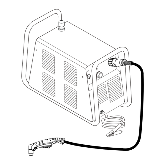
SECTION 4: OPERATION 4.01 Product Features A. General Features Gas Pressure Knob Handle and Leads Wrap Torch Leads Connector Control Panel Work Cable A-03287 and Clamp Manual 0-2967 OPERATION... - Page 20 B. Control Panel A-03283 1. ON / OFF Switch Controls input power to the power supply. Up is ON, down is OFF. 2. RUN / SET Switch RUN (up) position is for general torch operation. SET (down) position is for setting gas pressure and purging lines.
-
Page 21: Preparations For Operating
Check the torch for proper assembly and appropriate torch parts per the torch manual. The torch parts must correspond with the type of operation, and with the amperage output of this Power Supply (30 amps maximum). Use only genuine Firepower parts with this torch. B. Torch Connection Check that the torch is properly connected. - Page 22 F. Power On Place the Power Supply ON / OFF switch to the ON (up) position. AC indicator turns on. Gas indicator turns on when there is sufficient gas pressure for power supply operation. Minimum pressure for power supply operation is below the minimum for torch operation. A-03384 G.
- Page 23 H. Select Current Output Level Place RUN / SET switch to RUN (up) position. Gas flow will stop. Set the desired current output level. A-03386 Cutting Operation Refer to Section 1, Important Safety Precautions. Wear heavy welding gloves and protective clothing. Protect eyes with appropriate shielding.
- Page 24 K. Typical Cutting Speeds Cutting speeds vary according to torch output, the type of material being cut, and operator skill. Speeds shown are typical for this cutting system using air plasma to cut mild steel, with output current at 30 amps and torch held at 0 - 1/16"...
-
Page 25: Sequence Of Operation
4.03 Sequence of Operation The following is a typical sequence of operation for this power supply. Refer to Appendix 1 for block diagram. 1. Plug the input power cord into an active circuit. a. AC power is available at the Power Supply. 2. - Page 26 OPERATION Manual 0-2967...
-
Page 27: Service
SECTION 5: SERVICE 5.01 General Maintenance A. Each Use B. Every three months Check torch consumables for wear, replace if necessary. A. Check internal air filter, replace if necessary. 1. Shut off input power; turn off the gas supply. Bleed down the gas supply. - Page 28 4. Pull the upper end of the drain tube off the fitting on the filter bowl. 5. Unscrew the bowl. The filter element will be visible and still attached to the main body of the Regulator / Filter. 6. Unscrew the filter element from the Regulator / Filter body. The filter element will come off with a spool and some additional pieces.
- Page 29 B. Check Optional Single - Stage Filter Element, replace if necessary. 1. Shut off input power. 2. Shut off air supply, bleed down system. 3. Disconnect gas supply hose from filter. 4. Turn the Cover counter - clockwise. 5. Remove the Filter Element from the Housing and set Element aside to dry. 6.
-
Page 30: Common Faults
Torch standoff too high from workpiece c. Worn torch parts d. Improper cutting current e. Non - Genuine Firepower parts used 4. Short Torch Parts Life a. Oil or moisture in air source b. Exceeding system capability (material too thick) c. -
Page 31: Basic Troubleshooting Guide
5.03 Basic Troubleshooting Guide WARNING There are extremely dangerous voltage and power levels present inside this unit. Do not attempt to diagnose or repair unless you have had training in power electronics measurement and troubleshooting techniques. A. Basic Troubleshooting: Overview This guide covers basic troubleshooting. - Page 32 B. AC indicator flashing; Torch cannot be activated 1. System is in protective interlock mode. (User held torch trigger while turning on ON / OFF switch.) a. Release torch trigger, set ON / OFF switch to OFF (down). Return ON / OFF switch to ON (up) position. 2.
- Page 33 F. AC indicator ON; TEMP indicator 1. Air flow blocked a. Check for blocked air flow around the unit and correct condition. 2. Fan blocked a. Check and correct condition. 3. Unit is overheated a. Let unit cool down for at least 5 minutes. Make sure the unit has not been operated beyond Duty Cycle limit. Refer to duty cycle data in Section 2.
- Page 34 H. No cutting output; Torch activated; AC indicator ON; Gas flows; Fan operates 1. Work cable not connected to work piece, or connection is poor a. Make sure that work cable has a proper connection to a clean, dry area of the workpiece. 2.
- Page 35 M. Arc shuts off during operation; arc will not restart when torch switch is activated. 1. Power Supply is overheated (TEMP indicator a. Let unit cool down for at least 5 minutes. Make sure the unit has not been operated beyond Duty Cycle limit. Refer to Section 2 for duty cycle specifications.
- Page 36 SERVICE 5-10 Manual 0-2967...
-
Page 37: Parts Lists
The following items are included with the replacement power supply: input power cord and plug, work cable & clamp, gas pressure regulator / filter, and operating manual. Description Catalog # Firepower FP-38 Power Supply with input power cord 1445-0084 and 120 VAC, 20A plug 6.04 Power Supply Replacement Parts... -
Page 38: Options And Accessories
6.05 Options and Accessories Description Catalog # Multi-Purpose Cart (Not Shown) 1445-0913 Single - Stage Filter Kit (includes Filter & Hose) 1445-0080 Replacement Filter Body 9-7740 Replacement Filter Hose (not shown) 9-7742 Replacement Filter Element 9-7741 Housing Filter Element (Cat. No. 9-7741) Spring O-ring Assembled Filter... -
Page 39: Appendix 1: Sequence Of Operation (Block Diagram
APPENDIX 1: SEQUENCE OF OPERATION (BLOCK DIAGRAM) ACTION ACTION ACTION ACTION ACTION Close external ON / OFF switch RUN / SET switch Connect work cable RUN / SET switch to SET. to workpiece. disconnect switch. to ON. to RUN. Set output amperage RESULT RESULT RESULT... -
Page 40: Appendix 2: Data Tag Information
APPENDIX 2: DATA TAG INFORMATION West Lebanon, NH USA 03784 Manufacturer's Name and/or Logo, Location, Model and Revision Level, Serial Number Model: and Production Code Made in USA Type of Power Regulatory Standard Covering Supply (Note 1) This Type of Power Supply Output Current Type Duty Cycle Factor Output Range (Amperage/... - Page 41 This page left blank. Manual 0-2967 APPENDIX...
-
Page 42: Appendix 3: System Schematic
APPENDIX 3: SYSTEM SCHEMATIC PFC INDUCTOR INP UT 230V ONLY TEST E MC FILTER E12A CE ONLY CHASSIS GND (E12A) (E14A) (E15A) (E1) E14A 120/208/230V INPUT (E16A) 50/60HZ (E2) E15A STUD E16A E12B BIAS (E12B) FAN1 CONVERTER 12VDC BLACK (E14B) (E15B) E14B LOGIC AND CONTROL CIRCUITRY... - Page 43 MAIN OUTPUT INDUCTOR (E4) TORCH C70, 72, 81 C71, 73, 75 (E8) PILOT WORK (12) TORCH SWITCH (13) (14) +14VA AGND (15) +12VB BGND QUICK DISCONNECT TORCH SWITCH ON WORK PWM ON SOL1 GAS SOLENOID LOCATION COMP DESCRIPTION OVER-TEMP. SENSOR FAN, 4.5"...
- Page 44 APPENDIX Manual 0-2967...
Need help?
Do you have a question about the FP-38 and is the answer not in the manual?
Questions and answers