
Subscribe to Our Youtube Channel
Related Manuals for Firepower FP-82


Summary of Contents for Firepower FP-82
- Page 1 Plasma Cutting Power Supply Firepower FP-82 A-02990 Service Manual December 4, 2002 Manual No. 0-2871...
- Page 3 While the information contained in this Manual represents the Manufacturer's best judgement, the Manufacturer assumes no liability for its use. Plasma Cutting Power Supply Firepower FP-82 Service Manual Number 0-2871 www.firepoweronline.com Published by: Thermal Dynamics Corporation...
-
Page 4: Table Of Contents
TABLE OF CONTENTS SECTION 1: GENERAL INFORMATION ....................1-1 1.01 Notes, Cautions and Warnings ..............1-1 1.02 Important Safety Precautions ............... 1-1 1.03 Publications ....................1-2 1.04 Note, Attention et Avertissement ..............1-3 1.05 Precautions De Securite Importantes ............1-3 1.06 Documents De Reference ................ - Page 5 TABLE OF CONTENTS (continued) SECTION 6: PARTS LISTS ........................6-1 6.01 Introduction ....................6-1 6.02 Ordering Information ..................6-1 6.03 Major External Replacement Parts ............... 6-2 6.04 Front Panel Replacement Parts ..............6-3 6.05 Left Side Internal Replacement Parts ............6-4 6.06 Rear Panel Replacement Parts ..............
-
Page 7: General Information
SECTION 1: GASES AND FUMES GENERAL INFORMATION Gases and fumes produced during the plasma cutting process can be dangerous and hazardous to your health. 1.01 Notes, Cautions and Warnings • Keep all fumes and gases from the breathing area. Throughout this manual, notes, cautions, and warnings Keep your head out of the welding fume plume. -
Page 8: Publications
• Wear dry gloves and clothing. Insulate yourself from the work piece or other parts of the welding PLASMA ARC RAYS circuit. • Repair or replace all worn or damaged parts. Plasma Arc Rays can injure your eyes and burn your skin. •... -
Page 9: Note, Attention Et Avertissement
6. ANSI Standard Z49.2, FIRE PREVENTION IN THE USE ATTENTION OF CUTTING AND WELDING PROCESSES, obtain- able from American National Standards Institute, 1430 Broadway, New York, NY 10018 Toute procédure pouvant résulter l’endommagement du matériel en cas de non- 7. AWS Standard A6.0, WELDING AND CUTTING CON- respect de la procédure en question. - Page 10 • Eloignez toute fumée et gaz de votre zone de respira- • Ne touchez jamais une pièce “sous tension” ou “vive”; tion. Gardez votre tête hors de la plume de fumée portez des gants et des vêtements secs. Isolez-vous provenant du chalumeau. de la pièce de travail ou des autres parties du circuit de soudage.
-
Page 11: Documents De Reference
ultra-violets très forts. Ces rayons d’arc nuiront à vos 1.06 Documents De Reference yeux et brûleront votre peau si vous ne vous protégez pas correctement. Consultez les normes suivantes ou les révisions les plus récentes ayant été faites à celles-ci pour de plus amples •... - Page 12 9. Norme 70 de la NFPA, CODE ELECTRIQUE NA- TIONAL, disponible auprès de la National Fire Pro- tection Association, Batterymarch Park, Quincy, MA 02269 10. Norme 51B de la NFPA, LES PROCÉDÉS DE COUPE ET DE SOUDAGE, disponible auprès de la National Fire Protection Association, Batterymarch Park, Quincy, MA 02269 11.
-
Page 13: Declaration Of Conformity
1.07 Declaration of Conformity Manufacturer: Thermal Dynamics Corporation Address: 82 Benning Street West Lebanon, New Hampshire 03784 The equipment described in this manual conforms to all applicable aspects and regulations of the ‘Low Voltage Directive’ (European Council Directive 73/23/EEC as amended by Council Directive 93/68/EEC) and to the National legislation for the enforcement of this Directive. -
Page 14: Statement Of Warranty
THIS WARRANTY IS INVALID IF THE PRODUCT IS SOLD BY NON-AUTHORIZED PERSONS. The limited warranty periods for Firepower products shall be as follows: A maximum of four (4) years from date of sale to an authorized distributor and a maximum of three (3) years from date of sale by such distributor to the Purchaser, and with the following further limitations on such three (3) year period. -
Page 15: Introduction
C. Customer/Operator Responsibilities It is the customer/operator's responsibility to maintain the equipment and peripheral accessories provided by Firepower in good operating order in accordance with the procedures outlined in the operating manual, and to protect the equipment from accidental or malicious dam- age. - Page 16 INTRODUCTION Manual 0-2871...
-
Page 17: Description
(AC) is low or the DC voltage is higher low the technician, in turn, to properly train cus- than shown in the chart. tomer operating personnel. 3.02 General Description FirePower FP-82 Power Supply Duty Cycle 104° F 104° F 104° F Ambient The power supply provides 60 amp maximum output and (40°... -
Page 18: Power Supply Options And Accessories
3.04 Power Supply Options and Accessories The following accessories are available for this power supply. Refer to Section 6, Parts Lists, for catalog num- bers and ordering information. A. Single Stage Air Line Filter Kit A Single Stage In-Line Air Filter for use with com- pressed air shop systems. -
Page 19: Introduction
4.03 System Theory Firepower FP-82 Logic Board Indicators The Firepower FP-82 System is designed for hand opera- Indicator Meaning tion using the torch control bulkhead within the power CD on supply as the interface. -
Page 20: Common Operating Problems
Whenever pos- e. Cutting current too low sible, avoid excessive pilot arc time to improve parts life. Non-Genuine Firepower parts used B. Torch Standoff 2. Main Arc Extinguishes Improper standoff (the distance between the torch tip a. -
Page 21: Troubleshooting Guide - General Information
6. Repair as needed being sure to verify that unit is fully Basic troubleshooting and parts replacement procedures operational after any repairs. are described in the Firepower FP-82 Operating Manual. NOTES This Service Manual covers advanced troubleshooting, which requires power supply disassembly and live mea- Many signals are transferred between Printed Cir- surements. -
Page 22: Circuit Fault Isolation
3. Set the Power Supply controls as follows: 4.06 Circuit Fault Isolation • ON/OFF switch to OFF (Down) A. Controls and Indicators • RUN/SET switch to SET (Down) • CURRENT control (A) to maximum C. Main Input and Internal Power Tests 1. -
Page 23: Main Input And Internal Power Problems
E. Main Arc Test Make sure the work cable is firmly connected to the work- piece. Activate the torch to establish a pilot arc. Upper Upper screws screws Bring the torch to within 1/8"-3/8" (3-10 mm) of the work- piece to establish the main cutting arc, and note the fol- lowing: Lower screws... - Page 24 2. Main power disconnect switch open J23-3 J24-4 J18-6 J18-4 a. Close main power disconnect switch. J23-1 J24-3 J18-3 J18-5 3. Main power line fuses blown a. Replace main power line fuses. 4. Improper input power cable connections inside Power Supply Main PC Board a.
- Page 25 3. Faulty Wiring or Faulty Logic PC Board Fuse Check for 12 vdc at Main PC Board pin J24-3 to J24-4 from the Logic PC Board. Refer to Appen- dix 4, Main PC Board Layout. • If less than a volt, replace Logic PC Board. Auxiliary Transformer J23-3...
-
Page 26: Pilot Arc Problems
c. Measure across pins J41-1 and J41-3 on Power 2. Faulty Output Power PC Board Output PC Board. a. With ON/OFF switch in the OFF position, dis- connect J39 from the Output Power PCB. Acti- • If less than 2K ohms, replace Power Output vate the torch and check for continuity between PC Board. - Page 27 C. Gas flows; No arc in torch; No arc at spark gap on D. No arc or intermittent arc in torch; Gas flows; CD PC Board; AC indicator ON; TEMP indicator Spark at gap on CD PC Board; AC indicator ON; off;...
-
Page 28: Main Arc Problems
4.09 Main Arc Problems 4.10 Test Procedures Locate your symptom below: The test procedures in this subsection are referenced in the troubleshooting section. A. Main cutting arc will not initiate A. Safety Precautions 1. Work cable not connected. 1. Significant DC Voltage exists after removal of input a. - Page 29 5. Connect the volt/ohmmeter positive lead to the an- C. Diode Module Board Tests ode (+) of the diode and the negative lead to the cath- ode (-) of the diode for forward bias testing (refer to following figure). A properly functioning diode will WARNING conduct in the forward bias direction and indicate be- tween 0.3 to 0.9 volts.
- Page 30 2. Output Diode Module Board Circuit Test D. Main Input Power Test a. Use an ohmmeter set on the diode function and make the following measurements on the Output WARNING Diode Module Boards to Power Output PC Board. The following tests must be performed with the Output Diode A Output Diode B Indication...
- Page 31 E. Gas Solenoid Circuit Test WARNING Make the following voltage checks and replace the faulty part as required. The following tests must be performed with the 1. Place the RUN/SET Switch to the SET position. power supply connected to primary input power. 2.
- Page 32 d. With jumper between TP1 to TP7 still in place, ac- tivate the torch and measure for 250 vdc to 300 vdc between E61 (+) and E43 (-) on the Power Output PCB. Refer to Appendix 11. • If voltage is 0 vdc, replace IGBT Module. With jumper between TP-1 and TP-7 still in place, activate the torch and measure for approximately 250-300 vdc between J39-1 and J39-2.
-
Page 33: Repairs & Replacement Procedures
3. Attach the copper foil to a convenient and exposed electrical ground. This section describes parts replacement procedures which may be performed on the Firepower FP-82 Power 4. Connect the equipment primary cable ground to Supply. the same electrical ground as the wrist strap. -
Page 34: Major External Parts Replacement
B. Tube Handle Replacement 5.04 Major External Parts Replacement 1. Remove the cover per subsection 5.04-A. 2. Remove the Fan Assembly Panel per section Refer to Section 6.03 for Major External Replacement Parts 5.08-C. and overall detailed drawing. 3. Remove the four bolts and star washers securing the frame to the base of the unit. -
Page 35: Front Panel Parts Replacement
C. RUN/SET Switch Replacement 5.05 Front Panel Parts Replacement 1. Remove the cover per subsection 5.04-A. Refer to Section 6.04 for Front Panel Replacement Parts and overall detailed drawing. 2. Disconnect the two wires on the rear of the RUN/ SET Switch. -
Page 36: Left Side Internal Component Parts Replacement
5.06 Left Side Internal Component Parts Replacement Refer to subsection 6.05 for Left Side Internal Compo- nent Replacement Parts and overall detailed drawing. WARNING Disconnect primary power from the source before opening or disassembling the power supply. A. Fuse Replacement 1. - Page 37 D. IGBT Circuit PC Board or Input Diode PC 9. Install replacement components as follows: Board Replacement For input diodes: A new style input diode assem- bly replaces the old style input diode assembly. Follow the antistatic procedures in subsection 5.02. The Power Supply includes two IGBT Circuit PC Boards.
-
Page 38: Rear Panel Parts Replacement
6. Remove the Logic Board standoffs. chart(s). 7 . Carefully remove the original PC Board from the unit. Firepower 82 Input Diode Connections 8. Install the replacement PC Board by reversing the Input Diode To Main PCB steps above. It may be easier to install the PC Board if the Power Supply is turned on its right side first. - Page 39 6. Install the replacement Filter/Regulator Assem- C. Optional Single-Stage Filter Element bly by reversing the steps above. When connect- Replacement ing the gas tube to the Adapter Fitting, simply in- The Power Supply shuts down automatically when the sert the hose into the fitting until fully seated. It Filter Element becomes completely saturated.
- Page 40 D. Optional Two-Stage Filter Element E. Input Power Cable Replacement Replacement 1. Remove the cover per subsection 5.04-A. NOTE 2. Locate and label the input power cable connec- tions and disconnect the cable. The Two-Stage Air Filter has two Filter Elements. When the Filter Elements become dirty the Power 3.
-
Page 41: Right Side Internal Component Parts Replacement
6. Install the replacement Pressure Switch/Solenoid 5.08 Right Side Internal Component Assembly by reversing steps 2-5. Once installed, Parts Replacement the Solenoid Assembly should fit securely on the Heatsink Shroud. It should not be moveable. Refer to Section 6.07 Right Side Internal Component Parts List and overall detailed drawing. - Page 42 1) The inner edge of the Panel has tabs that 5. Use isopropyl alcohol to clean the heatsink and engage slots in the center chassis. Ensure the large flat surface on the back of the replace- that these tabs fully engage in the chassis. ment component(s).
- Page 43 E. Output Power PC Board Replacement F. Pilot Control Relay Replacement Follow the antistatic procedures in subsection 5.02. 1. Remove the Power Supply cover per section 5.04-A. NOTE 2. Push the clip on the front of the Heatsink Shroud Follow the electrostatic discharge instructions pro- to the left to release the Solenoid Assembly.
- Page 44 G. CD Transformer Replacement H. Heatsink Shroud Assembly Removal 1. Locate the CD PC Board Assembly. Label and dis- The Heatsink Shroud Assembly must be disengaged for connect wires E1 and E2. Refer to Appendix 6. access to either the Main Transformer or the Output In- ductor.
- Page 45 c. Ensure that the top edge of the Shroud does J. Output Inductor Assembly Replacement not hit the bottom edge of the CD PC Board. 1. Disengage the Heatsink Shroud per paragraph H. Stand the Heatsink Shroud Assembly against the Power Supply. 2.
- Page 46 3. Re-install the Heatsink Shroud as follows: a. Lift the Heatsink Shroud (Assembly) into po- sition. Studs on the Power Supply base pass through holes in the bottom flange of the Shroud. b. Swing the top edge of the Shroud Assembly into place.
-
Page 47: Parts Lists
SECTION 6: PARTS LISTS 6.01 Introduction A. Parts List Breakdown The parts lists provide a breakdown of all replaceable components. The parts lists are arranged as follows: Section 6.03 Major External Replacement Parts Section 6.04 Front Panel Replacement Parts Section 6.05 Left Side Internal Replacement Parts Section 6.06 Rear Panel Replacement Parts Section 6.07 Right Side Internal Replacement Parts Section 6.08 Options and Accessories... -
Page 48: Major External Replacement Parts
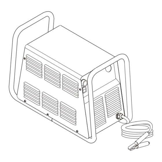
6.03 Major External Replacement Parts Item # Description Catalog # Cover with labels 9-8598-FP Rear Panel (Provide data tag information when ordering) 9-8595-FP Tube, roll handle 9-8573 Hardware: Screw, 10-32 x 1/5" PPH, swageform See Note 1 Washer, 1/4 External Star See Note 1 Screw, 1/4-20 x 3/4 Hex head See Note 1... -
Page 49: Front Panel Replacement Parts
6.04 Front Panel Replacement Parts Item# Description Catalog # Knob, Fluted, Skirted, 0.250 I.D. 9-8527 On/Off Rocker Switch, DPST 8-3258 Run/Set Switch, Rocker, SPST, Center Off 9-1042 Assembly, Pot/LED PCB 9-8004 Cable, Work, #6 AWG with Clamp, 20 Ft (6.1 m) 9-8528 A-03008 NOTE... -
Page 50: Left Side Internal Replacement Parts
6.05 Left Side Internal Replacement Parts Item # Description Catalog # Fuse 9-8588 Main Input Contactor 9-8587 Connector PCB 9-8576 PCB Assembly, Logic 9-8597 PCB Assembly Kit, IGBT Circuit 9-8578 Round Thermal Pad PCB Assembly Kit, Input Diode 9-8579 Rectangular Thermal Pad Solid Disk Round Thermal Pad PCB Assembly, Main Power... -
Page 51: Rear Panel Replacement Parts
6.06 Rear Panel Replacement Parts Item # Description Catalog # Assembly, Filter/Regulator 9-7514 Regulator/Filter Replacement Element 9-4414 Regulator Mounting Bracket 9-7589 Input Power Cable with plug 9-8596 Mounting Nut 9-8504 Pressure Gauge 9-1045 A-03005 NOTE Illustration may vary slightly from unit. Manual 0-2871 PARTS LISTS... -
Page 52: Right Side Internal Replacement Parts
6.07 Right Side Internal Replacement Parts Item # Description Catalog # Assembly, Pressure Switch/Solenoid Sol1, PS1 9-8563 Assembly, CD PC Board 9-8552 Coil, CD Transformer 9-8582 Pilot Relay 9-8574 Fan, 220V, 115 CFM M1, M2 9-7687 Assembly, Main Transformer 9-8589 Assembly, Output Inductor 9-8591 PCB Assembly, Output Power... - Page 53 PCR Cover Bulkhead Heatsink Shroud Heatsink Heatsink Work Cable Shroud A-03189 NOTE Illustration may vary slightly from unit. Manual 0-2871 PARTS LISTS...
-
Page 54: Options And Accessories
6.08 Options and Accessories Description Catalog # Single-Stage Filter Kit (Includes Filter And Hose) 7-7507 Replacement Filter Body 9-7740 Replacement Filter Element 9-7741 Replacement Filter Hose (Not Shown) 9-7742 Two-Stage Air Line Filter Kit (Includes Hose & Mounting Screws) 7-7500 Bracket, Filter Mounting (Not Shown) 9-7535 Two-Stage Air Filter Assembly... -
Page 55: Appendix 1: Input Wiring Requirements
APPENDIX 1: INPUT WIRING REQUIREMENTS Firepower 82 Input Wiring Requirements Input Power Input Current Input Suggested Sizes (See Notes) Voltage Freq. 1-Ph 3-Ph 1-Ph 3-Ph Fuse (Amps) Wire (AWG) Wire (Canada) (Volts) (Hz) (kVA) (kVA) (Amps) (Amps) 1-Ph 3-Ph 1-Ph... -
Page 56: Appendix 2: Sequence Of Operation (Block Diagram
APPENDIX 2: SEQUENCE OF OPERATION (BLOCK DIAGRAM) ACTION ACTION ACTION ACTION ON/OFF switch Close external RUN/SET RUN/SET switch to ON. disconnect switch. switch to RUN. to SET. RESULT RESULT RESULT RESULT AC indicator blinks for 8 Power to system. Gas flow stops. Gas solenoid open, seconds then steady on. -
Page 57: Appendix 3: Logic Pc Board Layout
APPENDIX 3: LOGIC PC BOARD LAYOUT TP12 TP10 A-03156 Logic Board Signals P1-27 Gate drive B signal P1-1 +12 vdc from Main PCB P1-28 Gate drive A return P1-2 +12 vdc from Main PCB P1-29 Gate drive A signal P1-3 DC Common P1-30 (-) out signal... -
Page 58: Appendix 4: Main Power Pc Board Layout
APPENDIX 4: MAIN POWER PC BOARD LAYOUT Fuse J32 J29 INPUT DIODE IGBT A IGBT B A-03149 Main Power PC Board Signals J18-1 J11-1 L1 Input J18-2 J11-2 Not Used J18-3 28VAC B J11-3 Not Used J18-4 28VAC A J11-4 L3 Input J18-5 On-Off Switch... - Page 59 J23-1 Not Used J43-1 +12vdc J23-1 Not Used J43-2 +12vdc J23-3 Not Used J43-3 DC Com J43-4 DC Com J24-1 Gas Solenoid J43-5 MC1 On J24-2 Gas Solenoid J43-6 Tip Sense J24-3 Pressure Switch J43-7 Run/Set J24-4 Pressure Switch J43-8 Press Good J24-5 Main Contactor...
-
Page 60: Appendix 5: Main Pc Board Wiring
APPENDIX 5: MAIN PC BOARD WIRING To Heat- To Press Sw/ Copper Sink Temp To Power Out- To Inductor Solenoid/ Strap Switch put Board Temp Switch Contactor To PCR/On-Off Switch/ To Main Input Run-Set Switch Contactor Fuse To Fans To Pot/LED PCB Secondary Transformer To Logic PCB... -
Page 61: Appendix 6: Cd Pc Board Layout
APPENDIX 6: CD PC BOARD LAYOUT A-03086 CD PC Board Signals J28-1 +12 vdc J28-2 CD Enable J28-3 Not Used J28-4 Not Used J28-5 J28-6 Not Used J28-7 Not Used J28-8 Manual 0-2871 APPENDIX... -
Page 62: Appendix 7: Led/Pot Pc Board Layout
APPENDIX 7: LED/POT PC BOARD LAYOUT A-01206 Pot/LED PC Board Signals J14-1 +10 vdc from Logic PC Board (J27-1) Pot High J14-2 Current Control to Logic PC Board (J27-2) Pot Wiper J14-3 Return for Current Control from Logic PC Board (J27-3) Pot Low J14-4 12vdc (J27-4) J14-5... -
Page 63: Appendix 8: Igbt Circuit Pc Board Layout
APPENDIX 8: IGBT CIRCUIT PC BOARD LAYOUT IGBT A IGBT B TP2A TP2B TP1A TP1B A-03154 Manual 0-2871 APPENDIX... -
Page 64: Appendix 9: Input Diode Pc Board Layout
APPENDIX 9: INPUT DIODE PC BOARD LAYOUT A-03155 NOTE: Refer to Appendix 5 for wiring connections. APPENDIX A-10 Manual 0-2871... -
Page 65: Appendix 10: Output Diode Pc Board Layout
APPENDIX 10: OUTPUT DIODE PC BOARD LAYOUT Output Diode B Output Diode A A-03152 NOTE: Refer to Appendix 11 for wiring connections. Manual 0-2871 A-11 APPENDIX... -
Page 66: Appendix 11: Power Output Pcb Wiring Diagram
APPENDIX 11: POWER OUTPUT PCB WIRING DIAGRAM To Main Power To Bulkhead To Torch Switch To PCR PC Board To CD PCB To Output Inductor Output Output Diode A Diode B To Output A-03153 To CD Coil Work Cable Inductor Power Output PC Board Signals J39-1 - Out... -
Page 67: Appendix 12: 28Vac Circuit Diagram
APPENDIX 12: 28VAC CIRCUIT DIAGRAM Line Voltage Fuse 3 4 5 6 ON/OFF Switch 1 2 5 6 primary Auxiliary Transformer Voltage Protection +12vdc Main Power PC Board A-03071 Manual 0-2871 A-13 APPENDIX... -
Page 68: Appendix 13: Maintenance Schedule
APPENDIX 13: MAINTENANCE SCHEDULE This schedule applies to all types of non-liquid cooled plasma cutting systems. Some systems will not have all the parts listed and those checks need not be performed. NOTE The actual frequency of maintenance may need to be adjusted according to the operating environment. Daily Operational Checks or Every Six Cutting Hours: Check torch consumable parts, replace if damaged or worn. - Page 69 Manual 0-2871 A-15 APPENDIX...
-
Page 70: Appendix 14: System Schematic
APPENDIX 14: SYSTEM SCHEMATIC INPUT DIODE IGBT PCB ASSEMBLY 19X1756 ASSEMBLY 19X1755 E12A E17A GATE 208/230V DRIVE COPPER SINGLE PHASE STRAP INPUT (78) GATE DRIVE (33) E19A E21A INRUSH +12VDC CHASSIS IGBT PCB ASSEMBLY 19X1756 E12B FILTERING +18V E17B GATE DRIVE 230V GATE... - Page 71 OUTPUT DIODE OUTPUT INDUCTOR ASSEMBLY E34B 19X1757 E39B MAIN E50B E(62) E48B E11A PILOT E(35) E53B E54B E56B J30 P30 E60B J31 P31 THRU SCREW TERMINAL OUTPUT DIODE ASSEMBLY E34A CHASSIS GND 19X1757 E39A E50A E11B E48A CD ASSEMBLY E53A 19X1751 E54A E56A...
Need help?
Do you have a question about the FP-82 and is the answer not in the manual?
Questions and answers