Table of Contents
Advertisement
Quick Links
Advertisement
Chapters
Table of Contents

Related Manuals for American Megatrends MI956


Summary of Contents for American Megatrends MI956
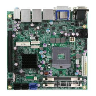
- Page 1 MI956 Intel Sandy Bridge / PCH ® Mini-ITX Motherboard USER’S MANUAL Version 1.0...
- Page 2 Acknowledgments AMI is a registered trademark of American Megatrends Inc. PS/2 is a trademark of International Business Machines Corporation. Intel and Intel® Sandy Bridge DC Mobile Processor are registered trademarks of Intel Corporation. Microsoft Windows is a registered trademark of Microsoft Corporation.
-
Page 3: Table Of Contents
Board Dimensions .............. 4 Installations ............5 Installing the CPU .............. 6 Installing the Memory............7 Setting the Jumpers............. 8 Connectors on MI956 ............12 BIOS Setup ............21 Drivers Installation ........49 Intel Chipset Software Installation Utility ......50 VGA Drivers Installation ..........53 Realtek HD Audio Driver Installation ...... - Page 4 This page is intentionally left blank. MI956 User’s Manual...
-
Page 5: Introduction
Integrated Graphics for DVI-I, DVI-D/HDMI/LVDS displays 4x SATA 2.0, 2x SATA 3.0, 8x USB 2.0, USB 3.0 (2 ports), 4x COM, Watchdog timer 1x PCI-E (x16), 1x Mini PCI-E Optional AMT (MI956AF only) MI956 User’s Manual... -
Page 6: Checklist
INTRODUCTION Checklist Your MI956 package should include the items listed below. The MI956 Mini-ITX motherboard This User’s Manual 1 CD containing chipset drivers and flash memory utility Serial ATA cable MI956 User’s Manual... -
Page 7: Mi956 Specifications
2x5 pin-header for Digital IO; 4-pin box header for LCD backlight control Yes (256 segments, 0, 1, 2…255 sec/min) Watchdog Timer System Voltage Others LAN Wakeup, EuP/ErP feature (Fintek F75160), UL 60950-1 2 Edition compatible Board Size 170mm x 170mm MI956 User’s Manual... -
Page 8: Board Dimensions
INTRODUCTION Board Dimensions MI956 User’s Manual... -
Page 9: Installations
INSTALLATIONS Installations This section provides information on how to use the jumpers and connectors on the MI956 in order to set up a workable system. The topics covered are: Installing the CPU ................6 Installing the Memory ................7 Setting the Jumpers ................8 Connectors on MI956 ................ -
Page 10: Installing The Cpu
INSTALLATIONS Installing the CPU The MI956 board supports rPGA988B socket for Intel® Sandy Bridge Dual Core mobile processors. The processor socket comes with a screw to secure the processor. As shown in the left picture below, loosen the screw first before inserting the processor. -
Page 11: Installing The Memory
INSTALLATIONS Installing the Memory The MI956 board supports two DDR3 memory socket for a maximum total memory of 8GB in DDR3 SO-DIMM memory type. Installing and Removing Memory Modules To install the DDR3 modules, locate the memory slot on the board and perform the following steps: 1. -
Page 12: Setting The Jumpers
INSTALLATIONS Setting the Jumpers Jumpers are used on MI956 to select various settings and features according to your needs and applications. Contact your supplier if you have doubts about the best configuration for your needs. The following lists the connectors on MI956 and their respective functions. -
Page 13: Jumper Locations On Mi956
INSTALLATIONS Jumper Locations on MI956 Jumpers on MI956 ................Page JP2, JP3, JP4: RS232/RS422/RS485 (COM1) Selection ....10 JP5: COM1 RS232 RI/+5V/+12V Power Setting ....... 10 JP6: COM2 RS232 RI/+5V/+12V Power Setting ....... 10 J10: LCD Panel Power Selection............11 J14: Flash Descriptor Security Overide (Factory use only)....11 J22: Clear ME Contents .............. -
Page 14: Jp2, Jp3, Jp4: Rs232/Rs422/Rs485 (Com1) Selection
1-3 & 2-4 JP5: COM1 RS232 RI/+5V/+12V Power Setting Setting Function Pin 1-2 +12V Short/Closed Pin 3-4 Short/Closed Pin 5-6 Short/Closed JP6: COM2 RS232 RI/+5V/+12V Power Setting Setting Function Pin 1-2 +12V Short/Closed Pin 3-4 Short/Closed Pin 5-6 Short/Closed MI956 User’s Manual... -
Page 15: J10: Lcd Panel Power Selection
Flash Descriptor Security Override Disabled Open (Default) Close Enabled J22: Clear ME Contents Setting Function Pin 1-2 Normal Short/Closed Pin 2-3 Clear ME Short/Closed J23: Clear CMOS Contents Setting Function Pin 1-2 Normal Short/Closed Pin 2-3 Clear CMOS Short/Closed MI956 User’s Manual... -
Page 16: Connectors On Mi956
INSTALLATIONS Connectors on MI956 Connector Locations on MI956 ............13 CN1: COM1 and COM2 Serial Ports ..........14 CN2: DVI-D and DVI-I Connector ........... 14 CN3: USB3.0 Connector ..............15 CN4: HDMI Connector ..............15 CN5: Gigabit LAN (Intel 82579LM) + USB 2/3 ........ 15 CN8: Gigabit LAN (Intel 82583V) + USB 0/1 ........ -
Page 17: Connector Locations On Mi956
INSTALLATIONS Connector Locations on MI956 MI956 User’s Manual... -
Page 18: Cn1: Com1 And Com2 Serial Ports
SHIELD 0/5 DATA 4+ DATA 5- DDC CLOCK DATA 5+ DDC DATA SHIELD CLK CLOCK - DATA 1- CLOCK + DATA 1+ SHIELD 1/3 DATA 3- DATA 3+ DDC POWER A GROUND2 A GROUND 1 A GROUND3 MI956 User’s Manual... -
Page 19: Cn3: Usb3.0 Connector
N.C. DATA 3+ N.C. DDC POWER N.C. A GROUND 1 N.C. CN3: USB3.0 Connector CN4: HDMI Connector CN5: Gigabit LAN (Intel 82579LM) + USB 2/3 CN8: Gigabit LAN (Intel 82583V) + USB 0/1 CN11: HD Audio Connector MI956 User’s Manual... -
Page 20: J1: Digital I/O
J2, J4: COM3, COM4 RS232 Serial Ports Signal Name Pin # Pin # Signal Name DCD# DSR# SIN# RTS# SOUT CTS# DTR# J6: ATX 12V Power Connector This connector supplies the CPU operating voltage. Pin # Signal Name Ground Ground +12V +12V MI956 User’s Manual... -
Page 21: Jp8, Jp7: Lvds Connectors (1St Channel, 2Nd Channel)
JP9: LCD Backlight Connector Pin # Signal Name +12V Backlight Enable Brightness Control Ground JP10, JP11: USB Connectors Signal Name Pin # Pin # Signal Name JP13: SPDIF I/O Pin # Signal Name SPDIF IN Ground SPDIF OUT Ground MI956 User’s Manual... -
Page 22: J24: Audio Pin Header For Chassis Front Panel
CN6, CN7, CN9, CN10, CN12, CN13: SATA Connectors Pin # Signal Name Ground Ground Ground CPU_FAN1: CPU Fan Power Connector Pin # Signal Name Ground +12V Rotation detection Control SYS_FAN1: System Fan1 Power Connector Pin # Signal Name Ground +12V MI956 User’s Manual... -
Page 23: Jp1: Lpc Debug Connector (Factory Use Only)
INSTALLATIONS JP1: LPC Debug Connector (Factory use only) J11: Mini-PCIE Connector JP12: SPI Flash Connector (Factory use only) MI956 User’s Manual... - Page 24 INSTALLATIONS This page is intentionally left blank. MI956 User’s Manual...
-
Page 25: Bios Setup
The topics covered in this chapter are as follows: BIOS Introduction ................22 BIOS Setup ..................22 Main BIOS Setup ................23 Advanced Settings ................24 Chipset Settings ................. 37 Boot Settings ..................44 Security Settings ................46 Save & Exit Settings ................47 MI956 User’s Manual... -
Page 26: Bios Introduction
<PgUp> and <PgDn> keys to change entries, <F1> for help and <Esc> to quit. When you enter the Setup utility, the Main Menu screen will appear on the screen. The Main Menu allows you to select from various setup functions and exit choices. MI956 User’s Manual... -
Page 27: Main Bios Setup
BIOS SETUP Main BIOS Setup This setup allows you to record some basic hardware configurations in your computer system and set the system clock. Aptio Setup Utility – Copyright © 2010 American Megatrends, Inc. Main Advanced Chipset Boot Security Save & Exit BIOS INFORMATION →... -
Page 28: Advanced Settings
F4: Save & EXIT ► CPU PPM Configuration ESC: Exit ►Sandybridge DTS Configuration REMARKS: Intel AMT Configuration 1.The is available only on MI956AF, not MI956F. 2.The EuP/ErP Power Saving Controller is available only on MI956F, not MI956AF. MI956 User’s Manual... -
Page 29: Pci Subsystem Settings
VGA Palette Snoop Enables or disables VGA Palette Registers Snooping. PERR# Generation Enables or disables PCI device to generate PERR#. SERR# Generation Enables or disables PCI device to generate SERR#. PCI Express Settings Change PCI Express devices settings. MI956 User’s Manual... -
Page 30: Maximum Payload
BIOS to select the value. ASPM Support Set the ASPM Level: Force L0s – Force all links to L0s State: AUTO – BIOS auto configure : DISABLE – Disables ASPM. Extended Synch If ENABLED allows generation of Extended Synchronization patterns. MI956 User’s Manual... -
Page 31: Acpi Settings
OS. ACPI Sleep State Select ACPI sleep state the system will enter, when the SUSPEND button is pressed. Lock Legacy Resources Enabled or Disabled Lock of Legacy Resources. S3 Video Repost Enable or disable S3 Video Repost. MI956 User’s Manual... - Page 32 ESC: Exit Wake system with Fixed Time Enables or Disables System wake on alarm event. When enabled, System will wake on the hr::min:: sec specified. Wake on PCIE PME Wake Event The options are Disabled and Enabled. MI956 User’s Manual...
-
Page 33: Cpu Configuration
OS (Windows Server 2003 SP1, Windows XP SP2, SuSE Linux 9.2, Re33dHat Enterprise 3 Update 3.) Intel Virtualization Technology When enabled, a VMM can utilize the additional hardware capabilities provided by Vanderpool Technology. MI956 User’s Manual... -
Page 34: Hardware Prefetcher
ESC: Exit Software Preserve Unknown SATA Port4 Empty Software Preserve Unknown SATA Port5 Empty Software Preserve Unknown SATA Controller(s) Enable / Disable Serial ATA Controller. SATA Mode Selection (1) IDE Mode. (2) AHCI Mode. (3) RAID Mode. MI956 User’s Manual... -
Page 35: Acpi Shutdown Temperature
USB Configure Enabled Select Screen PET Progress Enabled ↑↓ Select Item AMT CIRA Timeout Enter: Select Watchdog Disabled Change Field F1: General Help OS Timer F2: Previous Values BIOS Timer F3: Optimized Default F4: Save ESC: Exit MI956 User’s Manual... - Page 36 User can Enable/Disable PET Events progress to receive PET events or not. Watchdog Timer This configuration is supported only with MI956AF (with iAMT function). Enable/Disable Watchdog Timer. DPTF Configuration Advanced Main Chipset Boot Security Save & Exit DPTF Configuration Enable/Disable intel Dyamic Platform Thermal Framework. DPTF Disabled MI956 User’s Manual...
-
Page 37: Acoustic Management Configuration
DISABLE option will keep USB devices available only for EFI applications. USB3.0 Support Enable/Disable USB3.0 (XHCI) Controller support. XHCI Hand-off This is a workaround for OSes without XHCI hand-off support. The XHCI ownership change should be claimed by XHCI driver. MI956 User’s Manual... -
Page 38: Serial Port Configuration
F2: Previous Values F3: Optimized Default Power Failure Always off F4: Save ESC: Exit Serial Port Configuration Set Parameters of Serial Ports. User can Enable/Disable the serial port and Select an optimal settings for the Super IO Device. MI956 User’s Manual... - Page 39 PC health status. CPU Fan Smart Fan Control This field enables or disables the smart fan feature. At a certain temperature, the fan starts turning. Once the temperature drops to a certain level, it stops turning again. MI956 User’s Manual...
-
Page 40: Cpu Ppm Configuration
Disabled: ACPI thermal management uses EC reported temperature values. Enabled: ACPI thermal management uses DTS SMM mechanism to obtain CPU temperature values. Out of Spec: ACPI Thermal Management uses EC reported temperature values and TS SMM is used to handle Out of Spec. MI956 User’s Manual... -
Page 41: Chipset Settings
Wake on LAN Enable or disable integrated LAN to wake the system. (The Wake On LAN cannot be disabled if ME is on at Sx state.) SLP_S4 Assertion Width Select a minimum assertion width of the SLP_S4# signal. MI956 User’s Manual... -
Page 42: Pci Express Configuration
Enable or disable PCI Express Clock Gating for each root port. DMI Link ASPM Control The control of Active State Power Management on both NB side and SB side of the DMI link. PCIe-USB Glitch W/A PCIe-USB Glitch W/A for bad USB device(s) connected behind PCIE/PEG port. MI956 User’s Manual... -
Page 43: Pch Azalia Configuration
F2: Previous Values F3: Optimized Default F4: Save ESC: Exit Azalia Control Detection of the Azalia device. Disabled = Azalia will unconditionally disabled. Enabled Azalia will be unconditionally enabled. Auto = Azalia will enabled if present, disabled otherwise. MI956 User’s Manual... -
Page 44: System Agent Configuration
Change Field F1: General Help F2: Previous Values ► Graphics Configuration F3: Optimized Default ► Memory Configuration F4: Save ESC: Exit VT-d Check to enable VT-d function on MCH. Enable NB CRID Enable or disable NB CRID WorkAround. MI956 User’s Manual... -
Page 45: Graphics Configuration
Select the Video Device that will be activated during POST. This has no effect if external graphics present. Secondary booty display selection will appear based on your selection. VGA modes will be supported only on primary display. MI956 User’s Manual... -
Page 46: Lcd Control
Int-LVDS: VBIOS enables LVDS driver by Integrated encoder. SDVO LVDS: VBIOS enables LVDS driver by SDVO encoder. eDP Port-A: LFP Driven by Int-DisplayPort encoder from Port-A. Panel Color Depth Select the LFP Panel Color Depth: 18 Bit, 24 Bit. MI956 User’s Manual... -
Page 47: Memory Configuration
↑↓ Select Item Enter: Select Change Field F1: General Help CAS Latency (tCL) Minimum delay time F2: Previous Values F3: Optimized Default CAS to RAS (tRCDmin) Row Precharge (tRPmin) F4: Save ESC: Exit Active to Precharge (tRASmin) MI956 User’s Manual... -
Page 48: Boot Settings
RT code is executed above 1MB. Option ROM Messages Set display mode for Option ROM. Options: Force BIOS and Keep Current. INT19 Trap Response Enable: Allows Option ROMs to trap Int 19. Boot Option Priorities Sets the system boot order. MI956 User’s Manual... -
Page 49: Csm Parameters
Controls the execution of UEFI and Legacy Storage OpROM. Launch Video OpROM policy Controls the execution of UEFI and Legacy Video OpROM. Other PCI device ROM priority For PCI devices other than Network, Mass storage or Video defines which OpROM to launch. MI956 User’s Manual... -
Page 50: Security Settings
The password length must be F1: General Help in the following range: F2: Previous Values Minimum length F3: Optimized Default Maximum length F4: Save ESC: Exit Administrator Password User Password Administrator Password Set Setup Administrator Password. User Password Set User Password. MI956 User’s Manual... -
Page 51: Save Changes And Exit
Discard Changes done so far to any of the setup options. Restore Defaults Restore/Load Defaults values for all the setup options. Save as User Defaults Save the changes done so far as User Defaults. Restore User Defaults Restore the User Defaults to all the setup options. MI956 User’s Manual... - Page 52 BIOS SETUP This page is intentionally left blank. MI956 User’s Manual...
-
Page 53: Drivers Installation
LAN Drivers Installation ..............58 Intel® Management Engine Interface ..........62 ASMedia USB 3.0 Drivers ..............65 IMPORTANT NOTE: After installing your Windows operating system, you must install first the Intel Chipset Software Installation Utility before proceeding with the drivers installation. MI956 User’s Manual... -
Page 54: Intel Chipset Software Installation Utility
Plug & Play INF support for Intel chipset components. Follow the instructions below to complete the installation. 1. Insert the CD that comes with the board. Click Intel and then Intel(R) 7 Series Chipset Drivers. 2. Click Intel(R) Chipset Software Installation Utility. MI956 User’s Manual... - Page 55 DRIVERS INSTALLATION 3. When the Welcome screen to the Intel® Chipset Device Software appears, click Next to continue. 4. Click Yes to accept the software license agreement and proceed with the installation process. MI956 User’s Manual...
- Page 56 DRIVERS INSTALLATION 5. On the Readme File Information screen, click Next to continue the installation. 6. The Setup process is now complete. Click Finish to restart the computer and for changes to take effect. MI956 User’s Manual...
-
Page 57: Vga Drivers Installation
Driver, the Microsoft .NET Framework 3.5 SPI should be first installed. To install the VGA drivers, follow the steps below. 1. Insert the CD that comes with the board. Click Intel and then Intel(R) Q7 Series Chipset Drivers. 2. Click Intel(R) Q77 Chipset Family Graphics Driver. MI956 User’s Manual... - Page 58 DRIVERS INSTALLATION 3. When the Welcome screen appears, click Next to continue. 4. Click Yes to to agree with the license agreement and continue the installation. MI956 User’s Manual...
- Page 59 5. On the Readme File Information screen, click Next to continue the installation of the Intel® Graphics Media Accelerator Driver. 6. On Setup Progress screen, click Next to continue. 7. Setup complete. Click Finish to restart the computer and for changes to take effect. MI956 User’s Manual...
-
Page 60: Realtek Hd Audio Driver Installation
Realtek HD Audio Driver Installation Follow the steps below to install the Realtek HD Audio Drivers. 1. Insert the CD that comes with the board. Click Intel and then Intel(R) Q7 Series Chipset Drivers. 2. Click Realtek High Definition Audio Driver. MI956 User’s Manual... - Page 61 DRIVERS INSTALLATION 3. On the Welcome to the InstallShield Wizard screen, click Next to proceed with and complete the installation process. 4. The InstallShield Wizard Complete. Click Finish to restart the computer and for changes to take effect. MI956 User’s Manual...
-
Page 62: Lan Drivers Installation
DRIVERS INSTALLATION LAN Drivers Installation 1. Insert the CD that comes with the board. Click Intel and then Intel(R) 7 Series Chipset Drivers. 2. Click Intel(R) PRO LAN Network Driver. MI956 User’s Manual... - Page 63 DRIVERS INSTALLATION 3. Click Install Drivers and Software. 4. When the Welcome screen appears, click Next. MI956 User’s Manual...
- Page 64 DRIVERS INSTALLATION 5. Click Next to to agree with the license agreement. 6. Click the checkbox for Drivers in the Setup Options screen to select it and click Next to continue. MI956 User’s Manual...
- Page 65 DRIVERS INSTALLATION 7. The wizard is ready to begin installation. Click Install to begin the installation. 8. When InstallShield Wizard is complete, click Finish. MI956 User’s Manual...
-
Page 66: Intel® Management Engine Interface
REMARKS: The Intel iAMT 8.0 Drivers can be installed on MI956AF, not MI956F. Follow the steps below to install the Intel Management Engine. 1. Insert the CD that comes with the board. Click Intel and then Intel(R) AMT 8.0 Drivers. MI956 User’s Manual... - Page 67 DRIVERS INSTALLATION 2. When the Welcome screen to the InstallShield Wizard for Intel® Management Engine Components, click the checkbox for Install Intel® Control Center & click Next. 3. Click Yes to to agree with the license agreement. MI956 User’s Manual...
- Page 68 DRIVERS INSTALLATION 4. When the Setup Progress screen appears, click Next. Then, click Finish when the setup progress has been successfully installed. MI956 User’s Manual...
-
Page 69: Asmedia Usb 3.0 Drivers
1. Insert the CD that comes with the board. Click Intel and then Intel(R) 6 Series Chipset Drivers. 2. Click Intel(R) PRO LAN Network Driver. 2. When the Welcome screen to the InstallShield Wizard for Intel® Management Engine Components, click Next. 3. When InstallShield Wizard is complete, click Finish. MI956 User’s Manual... - Page 70 DRIVERS INSTALLATION This page is intentionally left blank. MI956 User’s Manual...
-
Page 71: Appendix
Graphics adapter Controller 360h - 36Fh Network Ports 3B0h - 3BFh Monochrome & Printer adapter 3C0h - 3CFh EGA adapter 3D0h - 3DFh CGA adapter 3E8h – 3EFh Serial Port #3(COM3) 3F8h - 3FFh Serial Port #1(COM1) MI956 User’s Manual... -
Page 72: Interrupt Request Lines (Irq)
Serial Port #2 IRQ4 Serial Port #1 IRQ5 Reserved IRQ6 Reserved IRQ7 Reserved IRQ8 Real Time Clock IRQ9 Reserved IRQ10 Serial Port #3 IRQ11 Serial Port #4 IRQ12 PS/2 Mouse IRQ13 80287 IRQ14 Primary IDE IRQ15 Secondary IDE MI956 User’s Manual... -
Page 73: Watchdog Timer Configuration
Fintek 81865, program abort.\n"); return(1); }//if (SIO == 0) if (argc != 2) printf(" Parameter incorrect!!\n"); return (1); bTime = strtol (argv[1], endptr, 10); printf("System will reset after %d seconds\n", bTime); if (bTime) EnableWDT(bTime); } else DisableWDT(); return 0; MI956 User’s Manual... - Page 74 //--------------------------------------------------------------------------- void DisableWDT(void) unsigned char bBuf; Set_F81865_LD(0x07); //switch to logic device 7 bBuf = Get_F81865_Reg(0xFA); bBuf &= ~0x01; Set_F81865_Reg(0xFA, bBuf); //disable WDTO output bBuf = Get_F81865_Reg(0xF5); bBuf &= ~0x20; bBuf |= 0x40; Set_F81865_Reg(0xF5, bBuf); //disable WDT //--------------------------------------------------------------------------- MI956 User’s Manual...
- Page 75 Lock_F81865 (void) outportb(F81865_INDEX_PORT, F81865_LOCK); //--------------------------------------------------------------------------- void Set_F81865_LD( unsigned char LD) Unlock_F81865(); outportb(F81865_INDEX_PORT, F81865_REG_LD); outportb(F81865_DATA_PORT, LD); Lock_F81865(); //--------------------------------------------------------------------------- void Set_F81865_Reg( unsigned char REG, unsigned char DATA) Unlock_F81865(); outportb(F81865_INDEX_PORT, REG); outportb(F81865_DATA_PORT, DATA); Lock_F81865(); //--------------------------------------------------------------------------- unsigned char Get_F81865_Reg(unsigned char REG) MI956 User’s Manual...
- Page 76 (F81865_BASE) #define F81865_DATA_PORT (F81865_BASE+1) //--------------------------------------------------------------------------- #define F81865_REG_LD 0x07 //--------------------------------------------------------------------------- #define F81865_UNLOCK 0x87 #define F81865_LOCK 0xAA //--------------------------------------------------------------------------- unsigned int Init_F81865(void); void Set_F81865_LD( unsigned char); void Set_F81865_Reg( unsigned char, unsigned char); unsigned char Get_F81865_Reg( unsigned char); //--------------------------------------------------------------------------- #endif //__F81865_H MI956 User’s Manual...