Table of Contents
Advertisement
Advertisement
Chapters
Table of Contents

Related Manuals for American Megatrends MI801


Summary of Contents for American Megatrends MI801
- Page 1 MI801 Intel Pineview-D +ICH8M ® Mini-ITX Motherboard USER’S MANUAL Version 1.1...
- Page 2 Acknowledgments AMI BIOS is a trademark of American Megatrends Inc. PS/2 is a trademark of International Business Machines Corporation. Intel and Luna-Pier are registered trademarks of Intel Corporation. Microsoft Windows is a registered trademark of Microsoft Corporation. Winbond is a registered trademark of Winbond Electronics Corporation.
-
Page 3: Table Of Contents
Checklist ................2 MI801 Specifications ............3 Board Dimensions .............. 4 Installations ............5 Installing the Memory............6 Setting the Jumpers............. 7 Connectors on MI801 ............11 BIOS Setup ............19 Drivers Installation ........39 Appendix ............47 A. I/O Port Address Map ..........47 B. - Page 4 This page is intentionally left blank. MI801 User’s Manual...
-
Page 5: Introduction
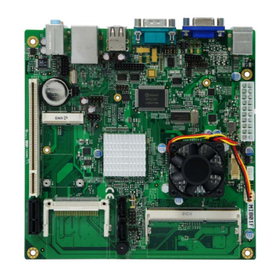
INTRODUCTION Introduction MI801F Mini ITX Motherboard MI801/MI801F Edge Connectors MI801 User’s Manual... -
Page 6: Checklist
INTRODUCTION Checklist Your MI801 package should include the items listed below. • The MI801 Mini-ITX motherboard • This User’s Manual • 1 CD containing chipset drivers and flash memory utility • Cable kit (USB, Serial port, Serial ATA) MI801 User’s Manual... -
Page 7: Mi801 Specifications
ICH8M built-in audio controller w/ Realtek ALC662 Codec Supports 5.1 CH audio (Line-out, Line-in & Microphone) LPC I/O Winbond W83627UHG-P: COM1(RS232/422/485) for MI801F / COM1(RS232 only) for MI801 COM2 ~COM4 (RS232 only) Hardware monitor (2 thermal inputs, 4 voltage monitor inputs, VID0-4 & 1 x Fan Header) Digital IO 4 in &... -
Page 8: Board Dimensions
INTRODUCTION Board Dimensions MI801 User’s Manual... -
Page 9: Installations
INSTALLATIONS Installations This section provides information on how to use the jumpers and connectors on the MI801 in order to set up a workable system. The topics covered are: Installing the Memory ................6 Setting the Jumpers ................7 Connectors on MI801 ................ 11... -
Page 10: Installing The Memory
INSTALLATIONS Installing the Memory The MI801 board supports one DDR3-800 memory. Remarks: D525 supports SO-DIMM x 1 (w/o ECC), Max. 4GB, Single channel Installing and Removing Memory Modules To install the DDR3 modules, locate the memory slot on the board and perform the following steps: 1. -
Page 11: Setting The Jumpers
INSTALLATIONS Setting the Jumpers Jumpers are used on MI801 to select various settings and features according to your needs and applications. Contact your supplier if you have doubts about the best configuration for your needs. The following lists the connectors on MI801 and their respective functions. -
Page 12: Jumper Locations On Mi801
INSTALLATIONS Jumper Locations on MI801 Jumper Locations on MI801 ............Page JP1: LCD Brightness Control Signal Level[MI801F] ......9 JP2: LCD Panel Power Selection [MI801F] ......... 9 JP4, JP6, JP7: RS232/422/485 (COM1) Selection[MI801F] ....9 JP5: COM2 RS232 RI/+5V/+12V Power Setting ......... 9 JP8: Clear CMOS Setting .............. -
Page 13: Jp2: Lcd Panel Power Selection [Mi801F]
3-5 & 4-6 1-3 & 2-4 1-3 & 2-4 JP7: JP7: JP7: 3-5 & 4-6 1-3 & 2-4 1-3 & 2-4 JP5: COM2 RS232 RI/+5V/+12V Power Setting Setting Function Pin 1-2 +12V Short/Closed Pin 3-4 Short/Closed Pin 5-6 Short/Closed MI801 User’s Manual... -
Page 14: Jp8: Clear Cmos Setting
INSTALLATIONS JP8: Clear CMOS Setting Setting Normal Clear CMOS MI801 User’s Manual... -
Page 15: Connectors On Mi801
INSTALLATIONS Connectors on MI801 The connectors on MI801 allows you to connect external devices such as keyboard, floppy disk drives, hard disk drives, printers, etc. The following table lists the connectors on MI801 and their respective functions. Connector Locations on MI801 ............12 CN1: PS/2 Keyboard and PS/2 Mouse Connectors...... -
Page 16: Connector Locations On Mi801
INSTALLATIONS Connector Locations on MI801 MI801 User’s Manual... -
Page 17: Cn1: Ps/2 Keyboard And Ps/2 Mouse Connectors
Signal Name Keyboard Mouse Signal Name Keyboard data Mouse data N.C. N.C. Keyboard clock Mouse clock N.C. N.C. CN3: COM1 RS232/RS422/RS485 [MI801 only supports RS232] Pin # Signal Name RS-232 R2-422 RS-485 DATA- DATA+ Ground Ground Ground MI801 User’s Manual... -
Page 18: Cn2: Vga Connector
CN6: 10/100/1000 RJ-45 and USB3/4 Ports CN7: Line-in, Line-out & Microphone Connector ATX1: ATX Power Supply Connector Signal Name Pin # Pin # Signal Name 3.3V 3.3V -12V 3.3V Ground Ground PS-ON Ground Ground Ground Ground Ground Power good 5VSB +12V MI801 User’s Manual... -
Page 19: J1: Lcd Backlight Connector[Mi801F]
Pin # Signal Name TX0- TX0+ Ground Ground TX1- TX1+ 5V/3.3V Ground TX2- TX2+ Ground Ground TXC- TXC+ DF13-20 5V/3.3V ENABKL +12V +12V J3: Digital I/O Signal Name Signal Name OUT3 OUT1 OUT2 OUT0 J4: DDR3 SO-DIMM MI801 User’s Manual... -
Page 20: J5: Com2/Rs232 Serial Port
Hard Disk Drive LED Connector: Pins 3 and 4 This connector connects to the hard drive activity LED on control panel. This LED will flash when the HDD is being accessed. Pin # Signal Name HDD Active +3.3V MI801 User’s Manual... -
Page 21: J9: Com3/Rs232, Com4/Rs232 Serial Port
Pin # Pin # Signal Name DSR3 DCD3 RTS3 RXD3 CTS3 TXD3 DTR3 Ground DSR4 DCD4 RTS4 RXD4 CTS4 TXD4 DTR4 Ground J10: SPI Flash Connector (factory use only) J11: USB5/USB6 Connector Signal Name Signal Name Ground Ground MI801 User’s Manual... -
Page 22: J12: Usb7/Usb8 Connector
PCI1: PCI Slot (supports 2 Master) PCIE1: PCIEX1 Slot [MI801F] FAN1: CPU Fan Power Connector This is a 3-pin header for system fans. The fan must be a 12V (500mA). Pin # Signal Name Ground +12V Rotation detection MI801 User’s Manual... -
Page 23: Bios Setup
BIOS SETUP BIOS Setup This chapter describes the different settings available in the AMI (American Megatrends, Inc.) BIOS that comes with the board. The topics covered in this chapter are as follows: BIOS Introduction .................... 20 BIOS Setup ......................20 Main BIOS Setup ..................... -
Page 24: Bios Introduction
<PgUp> and <PgDn> keys to change entries, <F1> for help and <Esc> to quit. When you enter the Setup utility, the Main Menu screen will appear on the screen. The Main Menu allows you to select from various setup functions and exit choices. MI801 User’s Manual... -
Page 25: Main Bios Setup
These defaults have been carefully chosen by both AMI and your system manufacturer to provide the absolute maximum performance and reliability. Changing the defaults could cause the system to become unstable and crash in some cases. MI801 User’s Manual... -
Page 26: Advanced Settings
The fields in each section are shown in the following pages, as seen in the computer screen. Please note that setting the wrong values may cause the system to malfunction. If unsure, please contact technical support of your supplier. MI801 User’s Manual... -
Page 27: Max Cpuid Value Limit
Enabled for Windows XP and Linux (OS optimized for Hyper-Threading Technology) and Disabled for other OS (OS not optimized for Hyper-Threading Technology). When Disabled, only one thread per enabled core is enabled. Intel SpeedStep(tm) tech (Pineview-M) Disabled: Disable GV3 Enabled: Enable GV3 MI801 User’s Manual... -
Page 28: Configure Sata As
Select Screen Serial PortC IRQ [IRQ11] ↑↓ Select Item Serial Port4 Address [2E8] Serial PortD IRQ [IRQ10] Change Field Restore on AC Power Loss [Power Off] General Help BackLight Control [Level-1] F10 Save and Exit ESC Exit MI801 User’s Manual... -
Page 29: Onboard Serial Port
The Hardware Health Configuration menu is used to show the operating temperature, fan speeds and system voltages. ACPI Shutdown Temperature The system will shut down automatically under OS with ACPI mode, when the CPU temperature reaches the configured temperature. MI801 User’s Manual... -
Page 30: Suspend Mode
64-bit Fixed System Description Tables. ACPI Version Features [ACPI v1.0] ACPI APIC support [Enabled] Different ACPI version Has some addition <- Select Screen ↑↓ Select Item Change Field General Help F10 Save and Exit ESC Exit MI801 User’s Manual... - Page 31 IDE AHCI Port1 [Not Detected] device. This displays AHCI Port2 [Not Detected] the status of auto detection of IDE devices. <- Select Screen ↑↓ Select Item Change Field General Help F10 Save and Exit ESC Exit MI801 User’s Manual...
-
Page 32: Power Button Mode
This option is used enable activity on the PCI PME (power management event) controller to wake up the system from a suspend or standby state Resume On RTC Alarm This option is used to specify the time the system should be awakened from a suspended state MI801 User’s Manual... -
Page 33: Legacy Usb Support
(12Mbps).This option is enabled by HiSpeed. BIOS EHCI Hand-Off Enabled/Disabled. This is a workaround for Oses without EHCI hand-off support. The EHCI ownership change should be claimed by EHCI driver. Legacy USB1.1 HC Support Support USB1.1 HC. MI801 User’s Manual... -
Page 34: Pcipnp Settings
This assigns IRQ to PCI VGA card if card requests IRQ or doesn't assign IRQ to PCI VGA card even if card requests an IRQ. IRQ# Use the IRQ# address to specify what IRQs can be assigned to a particular peripheral device. MI801 User’s Manual... -
Page 35: Boot Settings
When disabled, this displays normal POST messages. When enabled, this displays OEM Logo instead of POST messages. AddOn ROM Display Mode This allows user to force BIOS/Option ROM of add-on cards to be displayed during quiet boot. MI801 User’s Manual... - Page 36 When set to Enabled, the system waits for the F1 key to be pressed when error occurs. This allows option ROM to trap interrupt 19. Hit <DEL> Message Display This displays “Press <DEL> to run Setup” in POST. Interrupt 19 Capture This allows option ROMs to trap interrupt 19. MI801 User’s Manual...
-
Page 37: Security Settings
Security Settings Password. Supervisor Password: Not Installed User Password: Not Installed Change Supervisor Password <- Select Screen ↑↓ Change User Password Select Item Enter Change Boot Sector Virus Protection [Disabled] General Help F10 Save and Exit ESC Exit MI801 User’s Manual... -
Page 38: Advanced Chipset Settings
Configure DRAM Timing by SPD When this item is enabled, the DRAM timing parameters are set according to the DRAM SPD (Serial Presence Detect). When disabled, you can manually set the DRAM timing parameters through the DRAM sub-items. MI801 User’s Manual... -
Page 39: Internal Graphics Mode Select
This option is used to select the type of flat panel connected to the system. Options include: 640x480 / 800x600 / 1024x768 / 800x480 / 1024x600 1280x768 / 1280x800 / 1280x600. Spread Spectrum Clock By default, this field is set to Disabled. MI801 User’s Manual... -
Page 40: Usb Function
This option is disabled by default. HDA Controller This option is used to enable the Southbridge high definition audio controller. SMBUS Controller This option is enabled by default. Enable Onboard PCI option ROM This option is disabled by default. MI801 User’s Manual... -
Page 41: Exit Setup
These default settings are optimal and enable all high performance features. Load Failsafe Defaults This option allows you to load the troubleshooting default values permanently stored in the BIOS ROM. These default settings are non-optimal and disable all high-performance features. MI801 User’s Manual... - Page 42 BIOS SETUP This page is intentionally left blank. MI801 User’s Manual...
-
Page 43: Drivers Installation
Realtek High Definition Codec Audio Driver Installation ....44 Realtek RTL8111E LAN Drivers Installation ........45 IMPORTANT NOTE: After installing your Windows operating system (Windows XP/ Vista/ 7), you must install first the Intel Chipset Software Installation Utility before proceeding with the drivers installation. MI801 User’s Manual... -
Page 44: Intel Chipset Software Installation Utility
1. Insert the drivers DVD into the DVD drive. Click Intel and then Intel(R) Pineview Chipset Drivers. Click Intel(R) Chipset Software Installation Utility. 2. When the welcome screen to the Intel(R) Chipset Software Installation Utility appears, click Next to continue. MI801 User’s Manual... - Page 45 4. On the Readme Information screen, click Next to continue.When the Setup Progress screen appears, click Next to continue. 5. The Setup process is now complete. Click Finish to restart the computer and for changes to take effect. MI801 User’s Manual...
-
Page 46: Intel Pineview Chipset Family Graphics Driver Installation
1. Insert the drivers DVD into the DVD drive. Click Intel and then Intel(R) Pineview Chipset Drivers. Click Intel(R) Pineview Chipset Family Graphics Driver. 2. When the welcome screen of the Intel(R) Graphics Media Accelerator Driver appears, click Next to continue. MI801 User’s Manual... - Page 47 3. Click Yes to to agree with the license agreement and continue the installation. 4. Click Next in the Readme File Information window. 5. Click Next in the Setup Progress window. 6. Setup is now complete. Click Finish to restart the computer and for changes to take effect. MI801 User’s Manual...
-
Page 48: Realtek High Definition Codec Audio Driver Installation
2.When the welcome screen to InstallShield Wizard for Realtek High Definition Audio Driver appears, click Next to start the installation. 3.When InstallShield Wizard has finished performing maintenance operations on Realtek High Definition Codec Audio Audio Driver, click Finish to restart the computer. MI801 User’s Manual... -
Page 49: Realtek Rtl8111E Lan Drivers Installation
2. In the welcome screen of the InstallShield Wizard for REALTEK GbE & FE Ethernet PCI-E NIC Driver, click Next. 3. In the InstallShield Wizard screen, click Install to begin the installation. 4. InstallShield Wizard is completed. Click Finish to exit the Wizard. MI801 User’s Manual... - Page 50 DRIVERS INSTALLATION This page is intentionally left blank. MI801 User’s Manual...
-
Page 51: Appendix
Serial Port #2(COM2) 360h - 36Fh Network Ports 3B0h - 3BFh Monochrome & Printer adapter 3C0h - 3CFh EGA adapter 3D0h - 3DFh CGA adapter 3E8h - 3EFh Serial Port #3(COM3) 3F8h - 3FFh Serial Port #1(COM1) MI801 User’s Manual... -
Page 52: Interrupt Request Lines (Irq)
Interrupt Cascade IRQ3 Serial Port #2 IRQ4 Serial Port #1 IRQ5 Reserved IRQ6 Reserved IRQ7 Reserved IRQ8 Real Time Clock IRQ9 Reserved IRQ10 Serial Port #4 IRQ11 Serial Port #3 IRQ12 PS/2 Mouse IRQ13 80287 IRQ14 Primary IDE MI801 User’s Manual... -
Page 53: Watchdog Timer Configuration
(ucDid == 0xA2) //W83627UHG?? goto Init_Finish; } W627UHG_BASE = 0x2E; result = W627UHG_BASE; ucDid = Get_W627UHG_Reg(0x20); if (ucDid == 0xA2) //W83627UHG?? goto Init_Finish; } W627UHG_BASE = 0x00; result = W627UHG_BASE; Init_Finish: return (result); //--------------------------------------------------------------------------- void Unlock_W627UHG (void) MI801 User’s Manual... - Page 54 LD); Lock_W627UHG(); //--------------------------------------------------------------------------- void Set_W627UHG_Reg( unsigned char REG, unsigned char DATA) Unlock_W627UHG(); outportb(W627UHG_INDEX_PORT, REG); outportb(W627UHG_DATA_PORT, DATA); Lock_W627UHG(); //--------------------------------------------------------------------------- unsigned char Get_W627UHG_Reg(unsigned char REG) unsigned char Result; Unlock_W627UHG(); outportb(W627UHG_INDEX_PORT, REG); Result = inportb(W627UHG_DATA_PORT); Lock_W627UHG(); return Result; //--------------------------------------------------------------------------- MI801 User’s Manual...
- Page 55 (W627UHG_BASE) #define W627UHG_DATA_PORT (W627UHG_BASE+1) //--------------------------------------------------------------------------- #define W627UHG_REG_LD 0x07 //--------------------------------------------------------------------------- #define W627UHG_UNLOCK 0x87 #define W627UHG_LOCK 0xAA //--------------------------------------------------------------------------- unsigned int Init_W627UHG(void); void Set_W627UHG_LD( unsigned char); void Set_W627UHG_Reg( unsigned char, unsigned char); unsigned char Get_W627UHG_Reg( unsigned char); //--------------------------------------------------------------------------- #endif //__W627UHG_H MI801 User’s Manual...
- Page 56 //--------------------------------------------------------------------------- void WDTInitial(void) unsigned char bBuf; Set_W627UHG_LD(0x08);..............//switch to logic device 8 bBuf = Get_W627UHG_Reg(0x30); bBuf &= (~0x01); Set_W627UHG_Reg(0x30, bBuf); ..............//Enable WDTO //--------------------------------------------------------------------------- void WDTEnable(unsigned char NewInterval) unsigned char bBuf; Set_W627UHG_LD(0x08);......................Set_W627UHG_Reg(0x30, 0x01); ............... //enable timer MI801 User’s Manual...
- Page 57 APPENDIX bBuf = Get_W627UHG_Reg(0xF5); bBuf &= (~0x08); Set_W627UHG_Reg(0xF5, bBuf); ............//count mode is second Set_W627UHG_Reg(0xF6, NewInterval); ..............//set timer //--------------------------------------------------------------------------- void WDTDisable(void) Set_W627UHG_LD(0x08);......................Set_W627UHG_Reg(0xF6, 0x00);............//clear watchdog timer Set_W627UHG_Reg(0x30, 0x00); ..................... //--------------------------------------------------------------------------- MI801 User’s Manual...
-
Page 58: Digital I/O Sample Code
(W627UHG_BASE) #define W627UHG_DATA_PORT (W627UHG_BASE+1) //--------------------------------------------------------------------------- #define W627UHG_REG_LD 0x07 //--------------------------------------------------------------------------- #define W627UHG_UNLOCK 0x87 #define W627UHG_LOCK 0xAA //--------------------------------------------------------------------------- unsigned int Init_W627UHG(void); void Set_W627UHG_LD( unsigned char); void Set_W627UHG_Reg( unsigned char, unsigned char); unsigned char Get_W627UHG_Reg( unsigned char); //--------------------------------------------------------------------------- #endif //__W627UHG_H MI801 User’s Manual... - Page 59 (ucDid == 0xA2) //W83627UHG?? goto Init_Finish; } W627UHG_BASE = 0x00; result = W627UHG_BASE; Init_Finish: return (result); //--------------------------------------------------------------------------- void Unlock_W627UHG (void) outportb(W627UHG_INDEX_PORT, W627UHG_UNLOCK); outportb(W627UHG_INDEX_PORT, W627UHG_UNLOCK); //--------------------------------------------------------------------------- void Lock_W627UHG (void) outportb(W627UHG_INDEX_PORT, W627UHG_LOCK); //--------------------------------------------------------------------------- void Set_W627UHG_LD( unsigned char LD) MI801 User’s Manual...
- Page 60 LD); Lock_W627UHG(); //--------------------------------------------------------------------------- void Set_W627UHG_Reg( unsigned char REG, unsigned char DATA) Unlock_W627UHG(); outportb(W627UHG_INDEX_PORT, REG); outportb(W627UHG_DATA_PORT, DATA); Lock_W627UHG(); //--------------------------------------------------------------------------- unsigned char Get_W627UHG_Reg(unsigned char REG) unsigned char Result; Unlock_W627UHG(); outportb(W627UHG_INDEX_PORT, REG); Result = inportb(W627UHG_DATA_PORT); Lock_W627UHG(); return Result; //--------------------------------------------------------------------------- MI801 User’s Manual...
- Page 61 Winbond 83627UHG, program abort.\n"); return(1); Dio5Initial(); //for GPIO50..57 Dio5SetDirection(0x0F); //GP50..53 = input, GP54..57=output printf("Current DIO direction = 0x%X\n", Dio5GetDirection()); printf("Current DIO status = 0x%X\n", Dio5GetInput()); printf("Set DIO output to high\n"); Dio5SetOutput(0x0F); printf("Set DIO output to low\n"); Dio5SetOutput(0x00); return 0; MI801 User’s Manual...
- Page 62 Dio5SetDirection(unsigned char NewData) //NewData : 1 for input, 0 for output Set_W627UHG_LD(0x08); //switch to logic device 8 Set_W627UHG_Reg(0xE0, NewData); //--------------------------------------------------------------------------- unsigned char Dio5GetDirection(void) unsigned char result; Set_W627UHG_LD(0x08); //switch to logic device 8 result = Get_W627UHG_Reg(0xE0); return (result); //--------------------------------------------------------------------------- MI801 User’s Manual...
Need help?
Do you have a question about the MI801 and is the answer not in the manual?
Questions and answers