Table of Contents
Advertisement
Quick Links
User Manual
Electric Wire Saw WB12T
EDT EURODIMA GMBH
Diamond Technologies
Lagerstrasse 6
A-5071 Wals bei Salzburg
Tel.: +43 (0) 662 / 42 42 48
Fax: +43 (0) 662 / 42 42 48-20
e-Mail:
office@eurodima.com
www.eurodima.com
Branch in Germany:
Oberheinrieter Straße 30 - 32
D-74199 Unterheinriet
Tel.: +49 (0) 7130 / 40095 0
Fax: +49 (0) 7130 / 40095 20
e-Mail:
office@eurodima.com
www.eurodima.com
Advertisement
Table of Contents

Related Manuals for EDT Eurodima Braxx WB12T


Summary of Contents for EDT Eurodima Braxx WB12T
-
Page 1: User Manual
User Manual Electric Wire Saw WB12T EDT EURODIMA GMBH Diamond Technologies Branch in Germany: Lagerstrasse 6 Oberheinrieter Straße 30 - 32 A-5071 Wals bei Salzburg D-74199 Unterheinriet Tel.: +43 (0) 662 / 42 42 48 Tel.: +49 (0) 7130 / 40095 0... -
Page 2: Table Of Contents
WB12T Table of Contents Introduction ........................3 EU Declaration of Compliance ..................4 Intended Use........................5 Specifications........................5 General notes electric pneumatic saw WB12T.............. 6 Safety ..........................7 Dangerousness of the wire saw WB12T................7 Intended use ........................7 Danger ..........................8 Emissions.......................... -
Page 3: Introduction
The manual is not intended to replace correct training in operating the machine. We recommend training by qualified employees of EDT EURODIMA GMBH or by one of our authorized dealers. A protocol of receipt and training is then set up. -
Page 4: Eu Declaration Of Compliance
WB12T 2 EU D ECLARATION OF OMPLIANCE Manufacturer : EDT EURODIMA GMBH Lagerstraße 6 A-5071 Wals bei Salzburg Description: wire saw system, consisting of remote control panel, wire saw storage unit and wire guiding device Type: Wire saw system WB12T... -
Page 5: Intended Use
WB12T NTENDED Important safety note The EDT EURODIMA machines may not be used in conjunction with other brands of machines unless recommended or approved by EDT EURODIMA GMBH. Non-observance will void the warranty and any product liability. PECIFICATIONS Rated voltage... -
Page 6: General Notes Electric Pneumatic Saw Wb12T
WB12T WB12T ENERAL NOTES ELECTRIC PNEUMATIC SAW The wire saw system consists of a wire guiding device that is mounted at the cut. The wire saw unit wb12 is then positioned and/or mounted considering the specific application. The saw system is made up of the following components: stable machine frame;... -
Page 7: Safety
Applicability of use (concrete, masonry, steel, cast iron etc.) o Dimensions o Allowed cutting speed Allowed wire connector (preferent. EDT EURODIMA bwc9 quick wire connector) Chapped or deformed wires may not be used. Prior to every use, the diamond wire and the wire connector must be checked for damages. -
Page 8: Danger
WB12T 6.3 Danger Through wire sawing, particles are torn out of the material and the grinding medium with high speed. Due to the different workpiece forms, it is not possible to fit the safety guard exactly to the workpiece. Provide appropriate workwear (see personal protection measures). Always consider the safety safety clearance –... -
Page 9: Workplace
WB12T 6.6 Workplace The user’s workplace is at the control panel, which is to be placed laterally to the wire saw unit and out of the danger area (Pict. 3, see page 16). Caution – never stay in the alignment of the wire level! 6.7 Approved Operators The system may only be used, maintained and repaired by personnel who know the system and are aware of the potential dangers. -
Page 10: Emergency Measures
WB12T 6.10 Emergency measures In case of emergency, immediately turn off the system via emergency-stop button at the control panel. AFETY QUIPMENT Prior to every shift (after interrruption in use), after every maintenance or repair work, check the safety equipment. Check the specified conditions and position, the secure fixation, and the required functions. -
Page 11: Compressed Air Supply - Pneumatic Unit
WB12T 8.3 Compressed air supply – pneumatic unit The compressed air supply with 3-parts hose package between the WB12T wire storage and control panel is to be connected, via two control wires and an air-supply line to the frame of the saw unit, of air reservoir design. -
Page 12: Operation
WB12T 10 O PERATION Have you read and understood the safety instructions? You must not operate the system before. Mount the safety equipment correctly. Consider the personal safety measures. 11 M OUNTING THE CUTTING TOOLS The wires may only be mounted and installed by trained personnel. Only wires with a diameter of max. - Page 13 WB12T Procedure: conducting a wire saw cut Step 1 Drill the holes for guiding through the wire. When parts are cut out, the holes should be made bevelled to the cutting direction, as this facilitates the construction significantly. Step 2 Drill the holes for fixing the wire guiding device and, possibly, for fixing the unit when the surface is slippery (see 6.9, p.9).
-
Page 14: Maintenance And Service Of Wire Saw Wb12T
WB12T Step 12 For wet cuts, run the drive motors revolution up to a wire speed between approx. 20 and 30 m/sec. Step 13 For dry cuts, choose great wire length and low wire speed. Step 14 Choose the feed pressure so that there is no overload of the drive motor. The amperemeter should have a value between 25 and 30 ampere. -
Page 15: Compressor
The warranty includes the repair or replacement of defective parts free of charge. Parts subject to normal wear are excluded from this warranty. EDT EURODIMA is not liable for direct, indirect or consequential damage from defects, loss or expenses in connection with or resulting from the unsuitability of the device for a specific purpose. -
Page 16: Drawings And Pictures
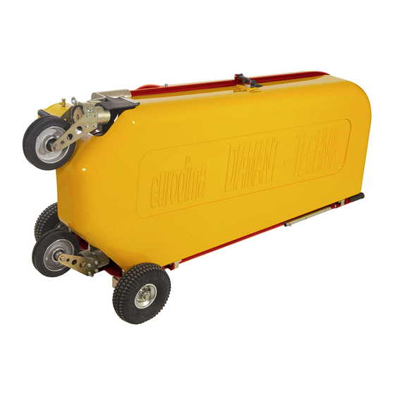
WB12T 16 D RAWINGS AND ICTURES Pict. 1: System, demounted Parts which are marked with “new design” look differently, having a new design and improved functionalities Hollow axle cover two handles Pos. 1 Removable protection device Pict. 2: System with protection cover... - Page 17 WB12T Pict. 3: danger zone...
- Page 18 WB12T Pict. 4: wire guiding layout...
- Page 19 WB12T Pict. 5: Views and dimensioning...
- Page 20 WB12T Hollow axle protection Pict. 6: Views without protection coverings...
- Page 21 WB12T Pict. 7: swivel pulley Pict. 8: notching pulley Hollow axle protection Pict. 9: Wire guiding device Pict. 10: Plunge saw device...
- Page 22 WB12T Pict. 11: pipe cutting device Pict. 12: Mounting at a vertical cut...
- Page 23 WB12T Pos.A: Carriage forward – tighten wire Pos.B: Carriage backward – release wire Pos.C: Neutral position – carriage standstill Pos.D: Pressure controller Pos.E: Manometer Pos.F: Drain valve Pos.G: Condensation drainage (lift to drain) Pos.H: Pressure release valve (at power failure, relieve pressure) Pos.1: Button –...
- Page 24 WB12T For finishing the cut, reset the wire pulleys! Pict. 14: Pulley setting...
Need help?
Do you have a question about the Braxx WB12T and is the answer not in the manual?
Questions and answers