
Related Manuals for ASROCK C226 WS


Summary of Contents for ASROCK C226 WS
-
Page 1: User Manual
C226 WS User Manual Version 1.0 Published June 2013 Copyright©2013 ASRock INC. All rights reserved. -
Page 2: Copyright Notice
(including damages for loss of profits, loss of business, loss of data, interruption of business and the like), even if ASRock has been advised of the possibility of such damages arising from any defect or error in the documentation or product. -
Page 3: Table Of Contents
Contents 1 Introduction ............5 1.1 Package Contents ............5 1.2 Specifications ..............6 1.3 Unique Features ............8 1.4 Motherboard Layout ............9 1.5 I/O Panel ..............11 1.6 Block Diagram ............. 12 2 Installation ............13 2.1 Screw Holes ..............13 2.2 Pre-installation Precautions ......... - Page 4 3.8 Security Screen ............. 55 3.9 Exit Screen ..............56 4 Software Support ..........57 4.1 Install Operating System ..........57 4.2 Support CD Information ..........57 4.2.1 Running Support CD ..........57 4.2.2 Drivers Menu ............57 4.2.3 Utilities Menu............57 4.2.4 Contact Information ..........
-
Page 5: Introduction
In case any modifications of this manual occur, the updated version will be available on ASRock website without further notice. You may find the latest VGA cards and CPU support lists on ASRock website as well. ASRock website http://www.asrock.com If you require technical support related to this motherboard, please visit our website for specific information about the model you are using. -
Page 6: Specifications
1.2 Specifications Physical Form Factor ATX Dimension 12'' x 9.6'' (30.5 cm x 24.4 cm) Status ® ® Intel Xeon processor E3-1200 v3 product family & Haswell i7, i5 , i3, Pentuim and Celeron Processor Socket Single socket (LGA1150) System Power 6 power phase design Phase... - Page 7 VGA Port 1 x HDMI + 1 x DVI-I + 1 x DisplayPort USB 2.0 Port USB 3.0 Port COM Port SPDIF eSATA3 1394 Audio 5 + 1 Jack COM Port Header IR Header CIR Header N/A Auxiliary Panel 1 (includes chassis intrusion, front LAN LED) Internal Header Connectors...
-
Page 8: Unique Features
1.3 Unique Features ASRock Instant Flash ASRock Instant Flash is a BIOS flash utility embedded in Flash ROM. This convenient BIOS update tool allows you to update system BIOS without entering operating systems first like MS- ® DOS or Windows . -
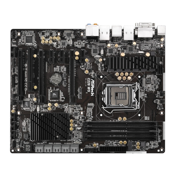
Page 9: Motherboard Layout
CPU_FAN1 ATX12V1 USB 3.0 Top: T: USB2 RJ-45 B: USB3 USB 2.0 T: USB2 B: USB3 USB 3.0 Top: T: USB0 RJ-45 B: USB1 C226 WS CHA_FAN3 USB3_4_5 PCIE7 PCIE6 PCIE5 CMOS Intel Battery PCIE4 C226 PCIE3 PCI2 64Mb Debug... - Page 10 No. Description Power Fan Connector (PWR_FAN1) ATX 12V Power Connector (ATX12V1) CPU Fan Connector (CPU_FAN1) CPU Fan Connector (CPU_FAN2) 2 x 240-pin DDR3 DIMM Slots (DDR3_A1, DDR3_B1) 2 x 240-pin DDR3 DIMM Slots (DDR3_A2, DDR3_B2) ATX Power Connector (ATXPWR1) USB 3.0 Header (USB3_4_5) SATA3 Connectors (SATA3_M0_M1) SATA3 Connectors (SATA3_M2_M3) SATA3 Connectors (SATA3_0_1)
-
Page 11: I/O Panel
1.5 I/O Panel No. Description No. Description USB 2.0 Ports (USB01) Microphone (Pink) DVI-I Port Optical SPDIF Out Port LAN RJ-45 Port USB 3.0 Ports (USB3_01) USB 2.0 Ports (USB23) IEEE 1394 Port LAN RJ-45 Port eSATA Connector Central / Bass (Orange) USB 3.0 Ports (USB3_23) Rear Speaker (Black) HDMI Port... -
Page 12: Block Diagram
1.6 Block Diagram PCI_E BUS 100MHz Haswell Bridge DIGITAL PORT B DIGITAL PORT C DIGITAL PORT C PCIE x1 100MHz PCIE x1 100MHz PCIE x1 100MHz Intel PCIE x1 100MHz PCIE x4 C226 100MHz PCIE x1 100MHz Lynx Point PCIE x1 100MHz PCIE x1 PCIE x1... -
Page 13: Installation
Chapter 2: Installation This is an ATX form factor (12.0" x 9.6", 30.5 x 24.4 cm) motherboard. Before you install the motherboard, study the configuration of your chassis to ensure that the motherboard fits into it. Make sure to unplug the power cord before installing or removing the motherboard. -
Page 14: Cpu Installation
2.3 Installing the CPU 1. Before you insert the 1150-Pin CPU into the socket, please check if the PnP cap is on the socket, if the CPU surface is unclean, or if there are any bent pins in the socket. Do not force to insert the CPU into the socket if above situation is found. - Page 16 Please save and replace the cover if the processor is removed. The cover must be placed if you wish to return the motherboard for after service.
-
Page 17: Installation Of Heatsink And Cpu Fan
2.4 Installing the CPU Fan and Heatsink... -
Page 18: Installation Of Memory Modules (Dimm)
2.5 Installation of Memory Modules (DIMM) This motherboard provides four 240-pin DDR3 (Double Data Rate 3) DIMM slots, and supports Dual Channel Memory Technology. For dual channel configuration, you always need to install identical (the same brand, speed, size and chip-type) DDR3 DIMM pairs. It is unable to activate Dual Channel Memory Technology with only one or three memory module installed. -
Page 20: Expansion Slot (Pci And Pci Express Slot)
2.6 Expansion Slots (PCI and PCI Express Slots) There are 2 PCI slots and 5 PCI Express slots on this motherboard. PCI slots: PCI slots are used to install expansion cards that have the 32-bit PCI interface. PCIE slots: PCIE7/PCIE5/PCIE4 (PCIE 2.0 x1 slot) is used for a PCI Express x1 lane width card. -
Page 21: Installing An Expansion Card
Installing an expansion card Step 1. Before installing an expansion card, please make sure that the power supply is switched off or the power cord is unplugged. Please read the documentation of the expansion card and make necessary hardware settings for the card before you start the installation. Step 2. -
Page 22: Crossfirex Tm Operation Guide
2.7 CrossFireX , 3-Way CrossFireX and Quad CrossFireX Operation Guide This motherboard supports CrossFireX , 3-way CrossFireX and Quad CrossFireX that allows you to install up to three identical PCI Express x16 graphics cards. Currently CrossFireX , 3-way CrossFireX and Quad ®... - Page 23 Step 3 Connect a VGA cable or a DVI cable to the monitor connector or the DVI connector of the graphics card that is inserted to PCIE6 slot. 2.7.2 Installing Three CrossFireX -Ready Graphics Cards Step 1 Insert one graphics card into PCIE6 slot, another graphics card to PCIE3 slot, and the other graphics card to PCIE1 slot.
-
Page 24: Driver Installation And Setup
2.7.3 Driver Installation and Setup Step 1 Power on your computer and boot into OS. Step 2 Remove the AMD drivers if you have any VGA drivers installed in your system. The Catalyst Uninstaller is an optional download. We recommend using this utility to uninstall any previously installed Catalyst drivers prior to installation. -
Page 25: Jumpers Setup
2.8 Jumpers Setup The illustration shows how jumpers are setup. When the jumper cap is placed on pins, the jumper is “Short”. If no jumper cap is placed on pins, the jumper is “Open”. The illustration shows a 3-pin jumper whose pin1 and pin2 are “Short”... -
Page 26: Onboard Headers And Connectors
2.9 Onboard Headers and Connectors Onboard headers and connectors are NOT jumpers. Do NOT place jumper caps over these headers and connectors. Placing jumper caps over the headers and connectors will cause permanent damage of the motherboard! Serial ATA3 Connectors These ten Serial ATA3 (SATA3) connectors support SATA data (SATA3_0_1: see p.9, No. -
Page 27: Tpm Header
(9-pin USB8_9) USB_PWR (see p.9, No. 21) DUMMY USB_PWR USB 3.0 Header Besides four default USB 3.0 IntA_P0_D+ IntA_P0_D- ports on the I/O panel, there is (19-pin USB3_4_5) IntA_P0_SSTX+ one USB 3.0 header on this IntA_P0_SSTX- (see p.9, No. 8) IntA_P0_SSRX+ motherboard. - Page 28 B. Connect Audio_R (RIN) to OUT2_R and Audio_L (LIN) to OUT2_L. C. Connect Ground (GND) to Ground (GND). D. MIC_RET and OUT_RET are for HD audio panel only. You don’t need to connect them for AC’97 audio panel. E. To activate the front mic. ®...
- Page 29 Auxiliary Panel Header This header supports multiple functions on the front panel, (18-pin AUX_PANEL1) including the front panel SMB, (see p.9, No. 24) internet status indicator and chassis intrusion pin. A. Front panel SMBus connecting pin (6-1 pin FPSMB) This header allows you to connect SMBus (System Management Bus) equipment.
- Page 30 Chassis and Power Fan Connectors Please connect the fan cables to the fan connectors and match (4-pin CHA_FAN1) the black wire to the ground pin. (see p.9, No. 22) (3-pin CHA_FAN2) (see p.9, No. 23) (3-pin CHA_FAN3) (see p.9, No. 28) (3-pin PWR_FAN1) (see p.9, No.
- Page 31 ATX 12V Power Connector Please connect an ATX 12V power supply to this connector. (8-pin ATX12V1) (see p.9, No. 2) Though this motherboard provides 8-pin ATX 12V power connector, it can still work if you adopt a traditional 4-pin ATX 12V power supply. To use the 4-pin ATX power supply, please plug your power supply along with Pin 1 and Pin 5.
-
Page 32: Dr. Debug
2.10 Dr. Debug Dr. Debug is used to provide code information, which makes troubleshooting even easier. Please see the diagrams below for reading the Dr. Debug codes. Status Code Description Please check if CPU is installed correctly and then clear CMOS. Problem related to memory, VGA card and other devices. -
Page 33: Driver Installation Guide
2.11 Driver Installation Guide To install the drivers to your system, please insert the support CD to your optical drive first. Then, the drivers compatible to your system can be auto-detected and listed on the support CD driver page. Please follow the order from top to bottom to install those required drivers. -
Page 34: Teaming Function Operation Guide
2.12 Dual LAN and Teaming Operation Guide Dual LAN with Teaming enabled on this motherboard allows two single connections to act as one single connection for twice the transmission bandwidth, making data transmission more effective and improving the quality of transmission of distant images. Fault tolerance on the dual LAN network prevents network downtime by transferring the workload from a failed port to a working port. -
Page 35: Uefi Setup Utility
Chapter 3: UEFI SETUP UTILITY 3.1 Introduction This section explains how to use the UEFI SETUP UTILITY to configure your system. The UEFI chip on the motherboard stores the UEFI SETUP UTILITY. You may run the UEFI SETUP UTILITY when you start up the computer. Please press <F2>... -
Page 36: Navigation Keys
3.1.2 Navigation Keys Please check the following table for the function description of each navigation key. Navigation Key(s) Function Description Moves cursor left or right to select Screens Moves cursor up or down to select items + / - To change option for the selected items <Tab>... -
Page 37: Oc Tweaker Screen
3.3 OC Tweaker Screen In the OC Tweaker screen, you can set up overclocking features. CPU Configuration CPU Ratio Use this item to change the ratio value of this motherboard. Intel SpeedStep Technology Intel SpeedStep technology is Intel’s new power saving technology. Pro- cessors can switch between multiple frequencies and voltage points to en- able power saving. - Page 38 Short Duration Power Limit Use this item to configure short duration power limit in watts. The default value is [Auto]. Primary Plane Current Limit Use this item to configure the maximum instantaneous current allowed for the primary plane. The default value is [Auto]. GT Frequency Configure the frequency of the integrated GPU.
- Page 39 CPU Cache Voltage Offset Configure the voltage for the CPU Cache. Setting the voltage higher may increase system stability when overclocking. System Agent Voltage Offset Configure the voltage for the System Agent. Setting the voltage higher may increase system stability when overclocking. CPU Analog IO Voltage Offset CPU I/O Analog Voltage.
-
Page 40: Advanced Screen
3.4 Advanced Screen In this section, you may set the configurations for the following items: CPU Configu- ration, Chipset Configuration, Storage Configuration, Super IO Configuration, ACPI Configuration, USB Configuration and Serial Port Console Redirection. Setting wrong values in this section may cause the system to malfunction. -
Page 41: Cpu Configuration
3.4.1 CPU Configuration Intel TXT(LT) Support Use this to enable or disable Intel Trusted Execution Technology . Intel Hyper Threading Technology Intel Hyper Threading Technology allows multiple threads to run on each core, so that the overall performance on threaded software is improved. Active Processor Cores Select the number of cores to enable in each processor package. - Page 42 Intel Virtualization Technology Intel Virtualization Technology allows a platform to run multiple operating systems and applications in independent partitions, so that one computer system can function as multiple virtual systems. Hardware Prefetcher Automatically prefetch data and code for the processor. Enable for better performance.
-
Page 43: Chipset Configuration
3.4.2 Chipset Configuration Primary Graphics Adapter This allows you to select [Onboard], [PCI] or [PCI Express] as the boot graphic adapter priority. The default value is [PCI Express]. VT-d ® ® Use this to enable or disable Intel VT-d technology (Intel Virtualization Technology for Directed I/O). - Page 44 Onboard HDMI HD Audio This allows you to enable or disable the Onboard HDMI HD Audio feature. Onboard 1394 This allows you to enable or disable the Onboard 1394 feature. Onboard LAN1 This allows you to enable or disable the Onboard LAN1 feature. Onboard LAN2 This allows you to enable or disable the Onboard LAN2 feature.
-
Page 45: Storage Configuration
3.4.3 Storage Configuration SATA Controller(s) Use this item to enable or disable the SATA Controller feature. SATA Mode Selection This item is for SATA3_0 to SATA3_5 ports. Use this to select SATA mode. Configuration options: [IDE Mode], [AHCI Mode] and [RAID Mode]. The default value is [AHCI Mode]. - Page 46 ® We recommend to use Intel C226 SATA ports (SATA3_0 to SATA3_5 ports) for your bootable devices. This will minimum your boot time and get the best performance. But if you still want to boot from Marvell SATA3 controller, you can still enable this in UEFI.
-
Page 47: Super Io Configuration
3.4.4 Super IO Configuration Serial Port Use this item to enable or disable the onboard serial port. Serial Port Address Use this item to set the address for the onboard serial port. Configuration options: [3F8h / IRQ4] and [3E8h / IRQ4]. -
Page 48: Acpi Configuration
3.4.5 ACPI Configuration Suspend to RAM Use this item to select whether to auto-detect or disable the Suspend-to- RAM feature. Selecting [Auto] will enable this feature if the OS supports it. Check Ready Bit Use this item to enable or disable the feature Check Ready Bit. ACPI HPET Table Use this item to enable or disable ACPI HPET Table. -
Page 49: Usb Configuration
USB Mouse Power On Use this item to enable or disable USB Mouse to turn on the system from the power-soft-off mode. 3.4.6 USB Configuration USB Controller Use this item to enable or disable the use of USB controller. Intel USB 3.0 Mode Use this item to enable or disable the use of Intel USB 3.0 mode. -
Page 50: Serial Port Console Redirection
3.4.7 Serial Port Console Redirection... -
Page 51: Tool
3.5 Tool UEFI Update Utility Instant Flash Instant Flash is a UEFI flash utility embedded in Flash ROM. This conve- nient UEFI update tool allows you to update system UEFI without enter- ® ing operating systems first like MS-DOS or Windows . -
Page 52: Hardware Health Event Monitoring Screen
3.6 Hardware Health Event Monitoring Screen In this section, it allows you to monitor the status of the hardware on your system, including the parameters of the CPU temperature, motherboard temperature, CPU fan speed, chassis fan speed, and the critical voltage. CPU Fan 1 &... -
Page 53: Boot Screen
3.7 Boot Screen In this section, it will display the available devices on your system for you to config- ure the boot settings and the boot priority. Fast Boot Fast Boot minimizes your computer’s boot time. There are three con- figuration options: [Disabled], [Fast] and [Ultra Fast]. - Page 54 Boot Beep Select whether the Boot Beep should be turned on or off when the system boots up. Please note that a buzzer is needed. Full Screen Logo Use this item to enable or disable OEM Logo. The default value is [En- abled].
-
Page 55: Security Screen
3.8 Security Screen In this section, you may set or change the supervisor/user password for the system. For the user password, you may also clear it. Secure Boot Use this to enable or disable Secure Boot. The default value is [Disabled]. -
Page 56: Exit Screen
3.9 Exit Screen Save Changes and Exit When you select this option, the following message “Save configuration changes and exit setup?” will pop-out. Select [Yes] to save the changes and exit the UEFI SETUP UTILITY. Discard Changes and Exit When you select this option, the following message “Discard changes and exit setup?”... -
Page 57: Software Support
Click on a specific item then follow the installation wizard to install it. 4.2.4 Contact Information If you need to contact ASRock or want to know more about ASRock, welcome to visit ASRock’s website at http://www.asrock.com; or you may contact your... -
Page 58: Trouble Shooting
Chapter 5: Troubleshooting 5.1 Troubleshooting Procedures Follow the procedures below to troubleshoot your system. Always unplug the power cord before adding, removing or changing any hardware components. Failure to do so may cause physical injuries to you and damages to motherboard components. 1. - Page 59 Other problems... 1. Try searching keywords related to your problem on ASRock’s FAQ page: http://www.asrock.com/support/faq.asp 2. Try downloading and updating the latest UEFI on ASRock’s website: http://www.asrock.com/support/download.asp...
-
Page 60: Technical Support Procedures
5.2 Technical Support Procedures If you have tried the troubleshooting procedures mentioned above and the problems are still unsolved, please contact ASRock’s technical support with the following information: 1. Your contact information 2. Model name, BIOS version and problem type.
Need help?
Do you have a question about the C226 WS and is the answer not in the manual?
Questions and answers